
scotta
Free Member
-
Joined
-
Last visited
-
If I was to rewire a car I would be looking to use a PDM - power distribution module also called PMU. They are a solid state device that simplifies wiring and does away with the traditional fuses. it allows for peak current management, retries if current exceeded, logic, timers, etc. There are a few on the market. If you were also going to change the gauges, look at CANbus gauges. They can integrate with the PMU. The PMU would also allow you to change inputs and outputs so you could repurpose beore or after installed. The PDU's cost a bit but you save on wiring and the time to install. https://www.ecumaster.com.au/products/ecumaster-pmu The PMU route is a bit of a rabbit hole as is CANbus, but does modernise the entire setup.
-
Thanks Kats, you amaze me with your knowledge!
-
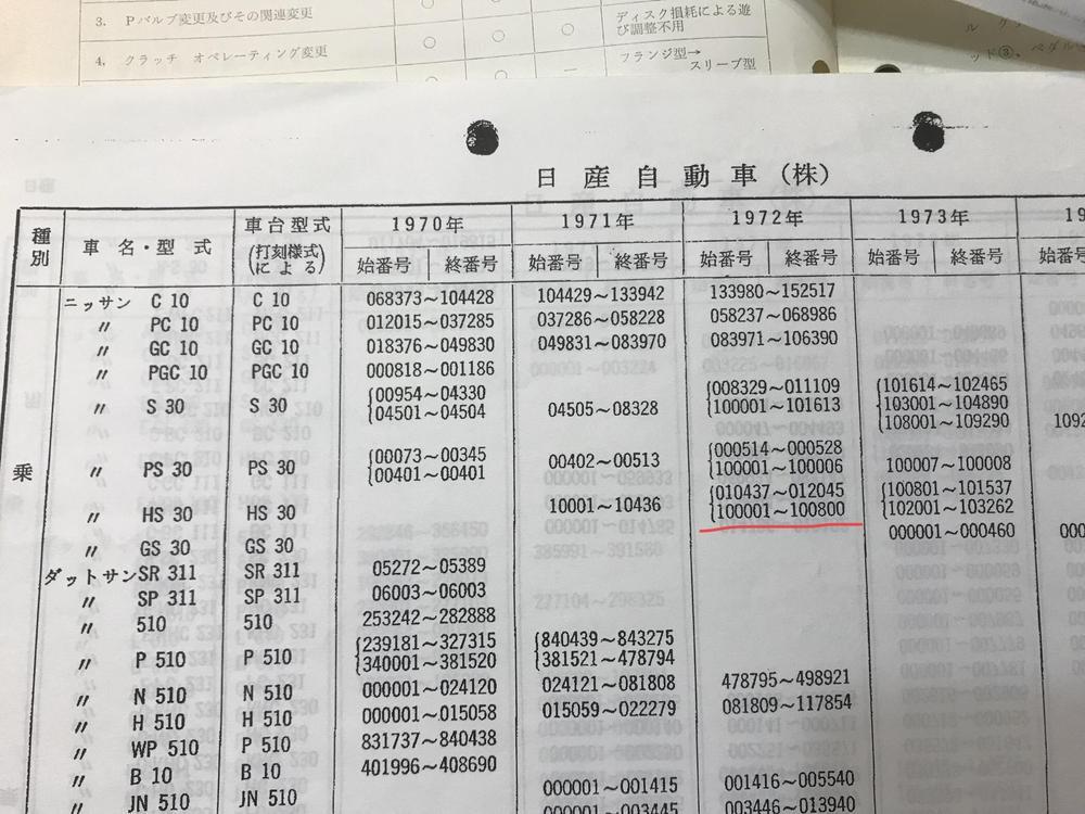
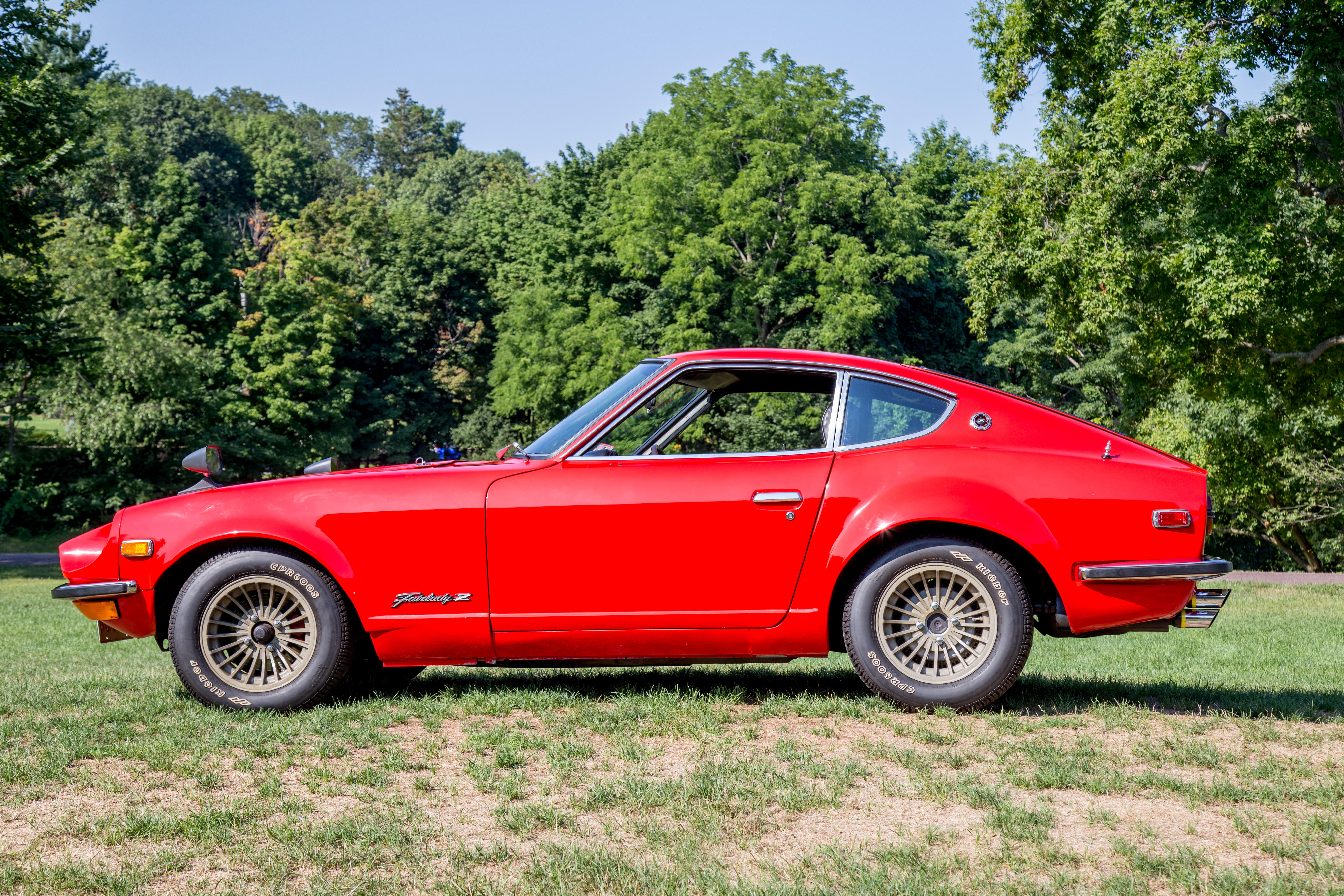
Gav, clearly a nice genuine JDM market car (8 track, indicator parking light switches, Fairlady Z on glove box, push to pass on the indicator stalk, z on horn button). However I would have expected the vin to be S30-103407, I understood all JDM cars did not have the H prefix. Might be a typo. I.e. my 1972 JDM fairlady Z-L is S30-100698. 2.0L engine, 5 speed. Made its way to Australia via Kentucky, USA.
-
Check out link below. I did just this.
-
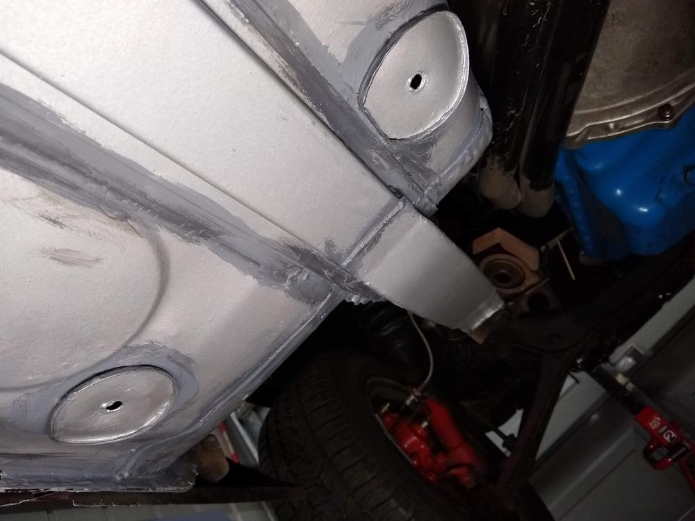
This might help. From my 1972 JDM Fairlady Z L. Floors were stripped back and rust patched. Excuse the thin layers of seam sealer. This has since been covered with underbody paint.

-
I would like to see this thread removed.
-
The foot rests were standard items on JDM cars. My 1972, FZ-L has it. Note that the floor has reinforcing where it bolts through.
-
-
Patcon. the design of that circuit also uses a separate 12 V supply that would have to be routed. I've also simplified the circuit such that it only uses the 12V coming from the original switch. i.e. no additional 12v wiring needed. This keeps it very simple to put in.
-
That was my starting proposition. However because of the need to pulse power on both wires (for the antenna I had) before removing the green power to make it go down, I had to modify the circuit.
-
It is a 1972 Japanese domestic market fairlady z. Yes it has a rear window demister switch and the two parking light switches. Plus the 8 track radio
-
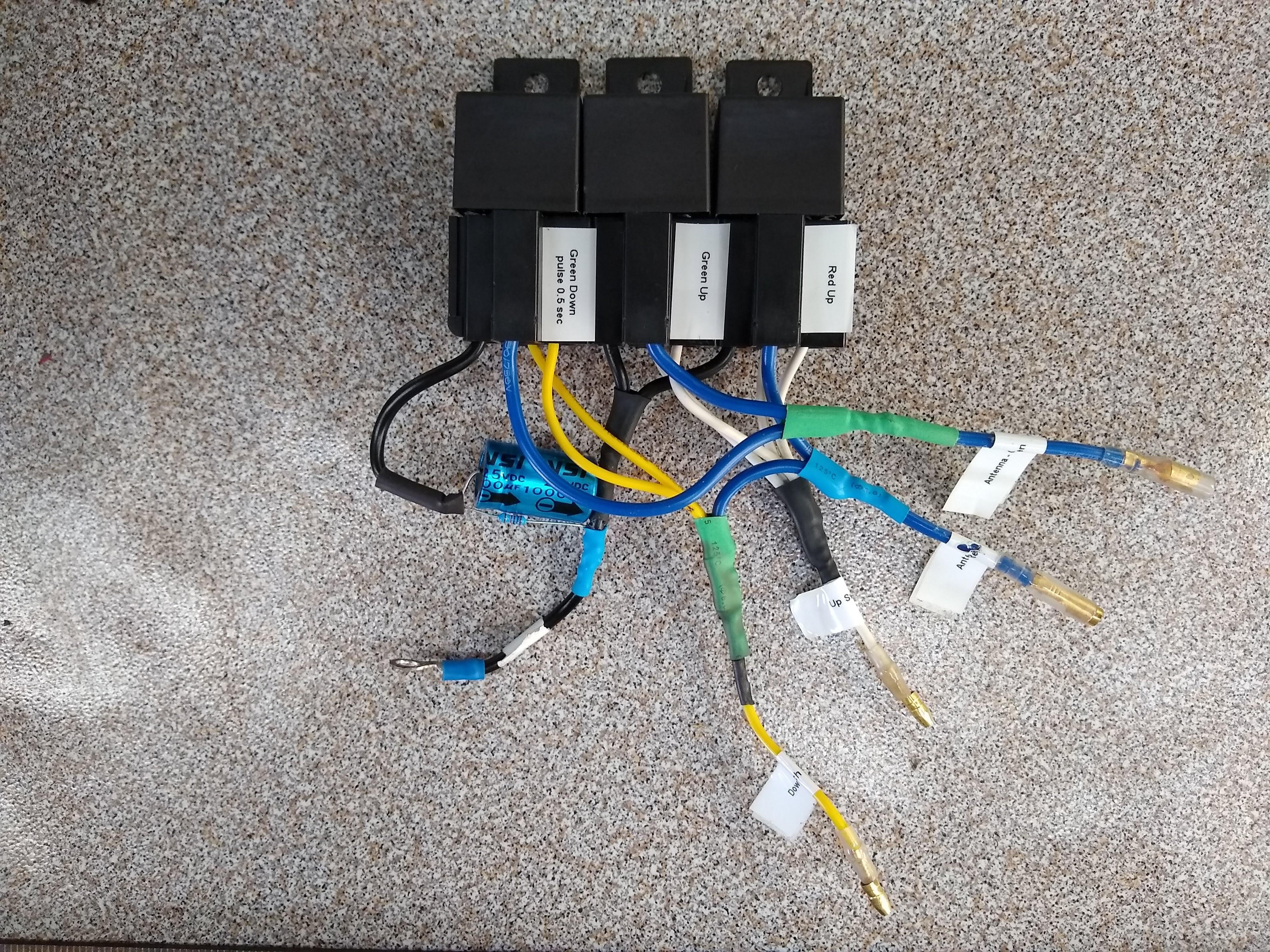
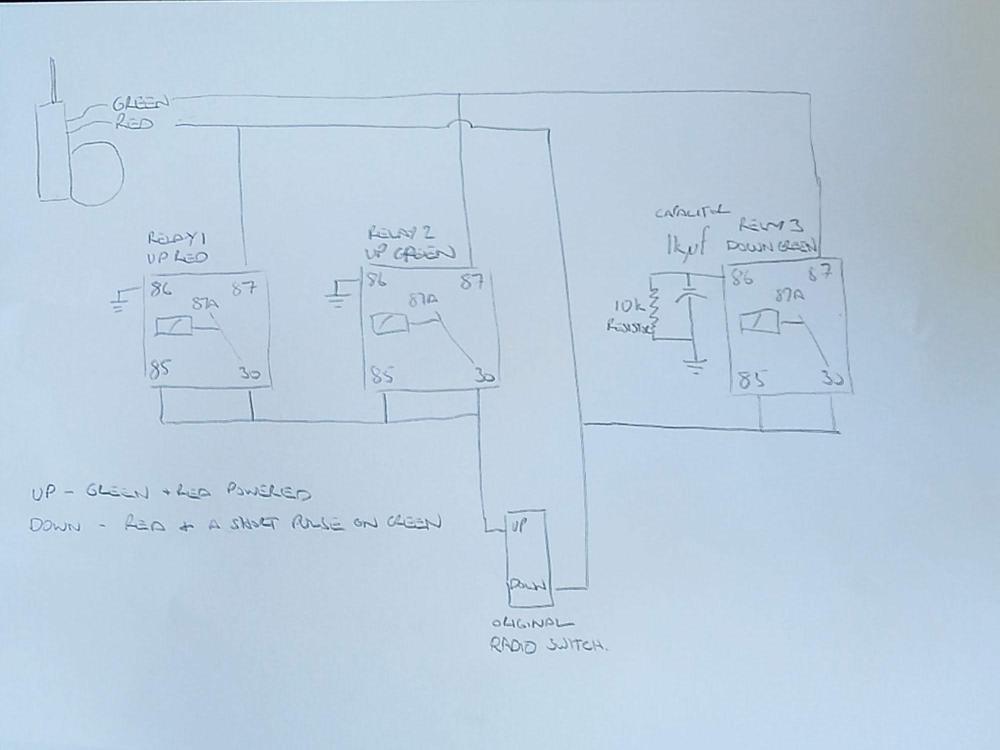
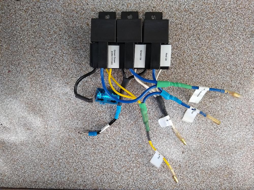
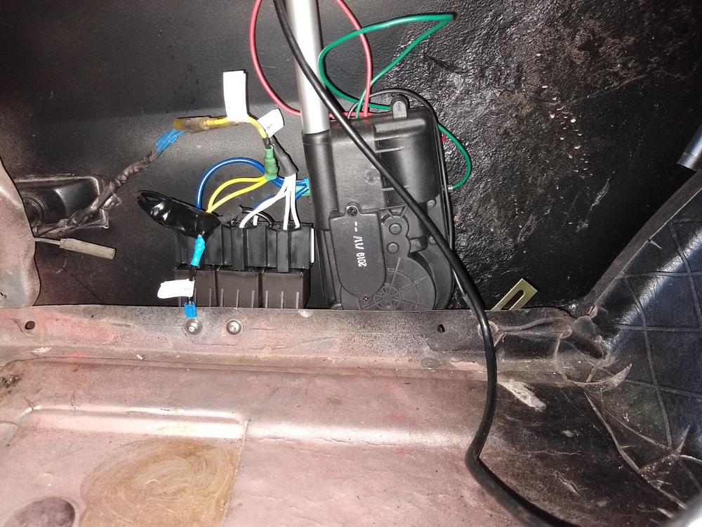
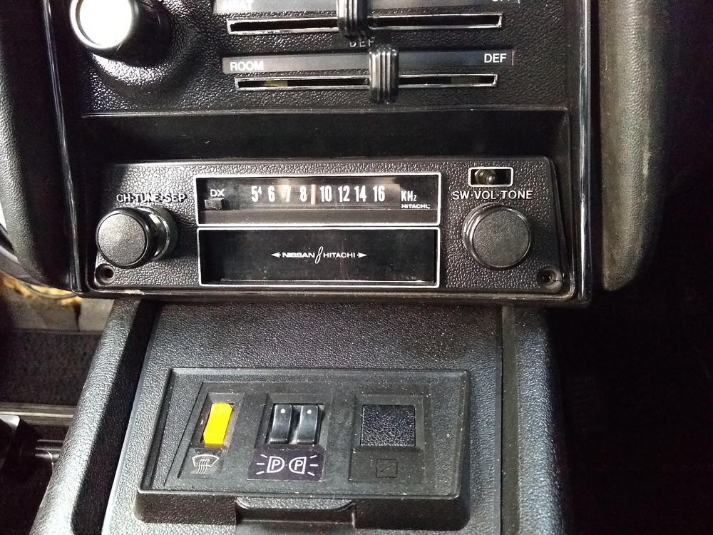
Instructions on how to install a new inexpensive power antenna to work with the OEM antenna up/down switch.When I purchased my 1972 Fairlady Z-L it only had the 8-track face plate and a loose antenna switch. The 8-track unit itself was missing. I purchased an old 8 track off ebay, 3d printed some parts to build a mock up unit. It does not play but cartridges can be inserted, the buttons work and it looks original. The up/down switch is secured and functional. I am in the process of putting in a secret audio head unit so that I have a radio and use Bluetooth. I wanted to replace the manual antenna with a power antenna. However new antennas operate differently. Original antenna uses two wires, power one and the unit goes up, power the other and the unit goes down.New antennas operate like this;up - power to both red and green wiresdown - power to red wire only. (however I discovered that the antenna needs a pulse to both wires first to turn it on.)I achieved this with the use of three bosch type relays, a capacitor (1000 microfarad) and resistor (10k Ohm) to provide a pulse to the green wire. The capacitor/resistor powers the third relay for about 0.5 Seconds Relay 1 and 2 for up ensure that the circuits are isolated from the down wiring. Relay 3 provides the pulse to green for down.
-
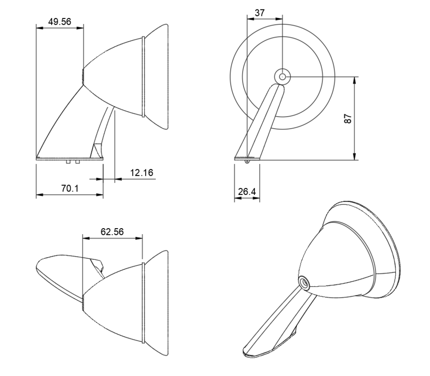
Here are the dimensions.
-
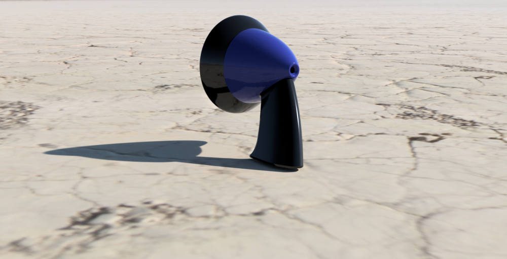
Guillermo, I did get the info. In fact one of the members was kind enough to lend me one to make measurements. I've have modelled the externals and some of the internals in Fusion360. I am still working on the internal spring mechanism. I have a set of short arm mirrors. I will replace the arm and bullet with 3d printed versions.


-
Great to see another one surface. Same year as mine, S30-100698, with original 2l engine. (They changed the numbering format in that year, adding an additional digit. //////0 Mine also moved to the us with a returning service man. There were a couple of different models produced; FZ and FZ-L. The L had carpets, a rally clock and an 8 track. Does yours have a clock?