rcv
Free Member
-
Joined
-
Last visited
Everything posted by rcv
-
 I pulled the valve cover off and cranked it for a few seconds, and it looks like I'm actually getting some oil pressure. What do you all think, should I just stop worrying and start this thing?
 -
Yup, I filled the pump with oil and turned it a few times before installing it. I took pictures of the pickup installed too, so I’m pretty sure it’s there unless a gremlin stole it.
-
@Mark Maras Doesn’t oil go flying everywhere? I’ve thought about building an acrylic valve cover like that Restoration For Beginners guy:
-
Good idea guys, thanks - I just ordered a mechanical gauge and some adapters. Is 10PSI good enough at cranking RPM to consider the engine good to start? In case you can't tell, I'm super nervous about starting it for the first time so I want to do as much groundwork as possible.
-
Ok, I'm out of town for the next week but I'll grab the sensor when I get back and send you some scans. DM me if you don't hear from me in two weeks just to remind me.
-
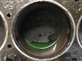
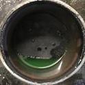
I know this topic has been discussed quite a few times (and usually starts with this same sentence). I just finished rebuilding my L24, and after getting it in the car and filling it up with oil I decided to give it a test crank to make sure I could build oil pressure. Nada, zip, nothing, 0 PSI. Here's what I've tried so far: Filled the oil filter to the brim Pulled the spark plugs Put ~10PSI of compressed air down the dipstick tube Replaced the sender wire connector with a brand new one Tried with both the old sender and a brand new one (https://zcardepot.com/products/oil-pressure-gauge-sender-240z-260z-280z-70-77?_pos=2&_sid=c56c8c526&_ss=r) Cranked in 15 second increments ~10 times The good news is that when I pull the valve cover off there's oil in the head, and the assembly lube I drenched the cam in seems to be replaced with oil. Also, when I remove the oil pressure sender fresh oil quickly oozes out of the hole. This gives me hope that it's just a sensing problem and not actually a pressure problem?. To test the gauge I grounded the connecting wire, and the needle shot up to full 140PSI, which indicates that the gauge itself is working properly. Then, just on a whim I tested the voltage on the unplugged connector. What's weird is that I don't get a solid voltage between the unplugged connector and ground. It seems to be oscillating somewhere between 0-12 volts. I don't have an oscilloscope at home and my crappy $20 multimeter can't give me any more details but it's definitely not a solid signal. Is this expected? I assumed the gauge was basically working as a DC voltage divider which would mean that signal should be a solid voltage. Also, how worried should I be about cranking the engine like this? I used a ton of assembly lube when I put everything together, but it's been almost 6 months since I put the crank in and buttoned up the oil pan. I've probably accumulated a little over 2 minutes of cranking time in 15 second intervals so far.
-
Just a quick update for anyone else who runs across this: The engine/transmission is now in the car, and even though it's not running yet I did some test runs by pushing my car down my driveway, putting it into gear and then slowly releasing the clutch. Things feel pretty good, so I'm going to call this a success so far. I'll post a final update once the car is driving.
-
I've done a little bit of 3D scanning using the front-facing IR camera on my iPhone: https://platform.standardcyborg.com/sharescan/igyMyZc7 I have access to an Intel RealSense camera at work that I could bring home and capture some more higher quality point clouds if that would help you. You would have to do the legwork of turning the point clouds into a mesh though. It's not going to produce a drop-in 3D model, but might provide a good dimensional reference when you make the actual models in Blender or whatever. If you can come up with a good plan, I'm happy to spend an afternoon doing the scans at some point.
-
Yeah, I agree. I can't really wrap my head around our disparities in measurements. We seem to get the distance to the pivot mounting flat, and our pivots seem to be the same dimensions. However, we get different measurements from the bellhousing face to the pivot even when I take my extra washers into account. You don't happen to have the original pressure plate that came with the car do you? My theory is that the one that goes with the 71A transmission is actually taller than the one that goes with the 71B. I'm getting pretty close to putting this into the cold case files anyway. I did take some 3d scans of the inside of the bellhousing just in case I want to reference it later. You can check out a preview here: https://platform.standardcyborg.com/sharescan/igyMyZc7. I took a couple that I'll align and mesh together at some point, but just let me know if anyone wants the raw data.
-
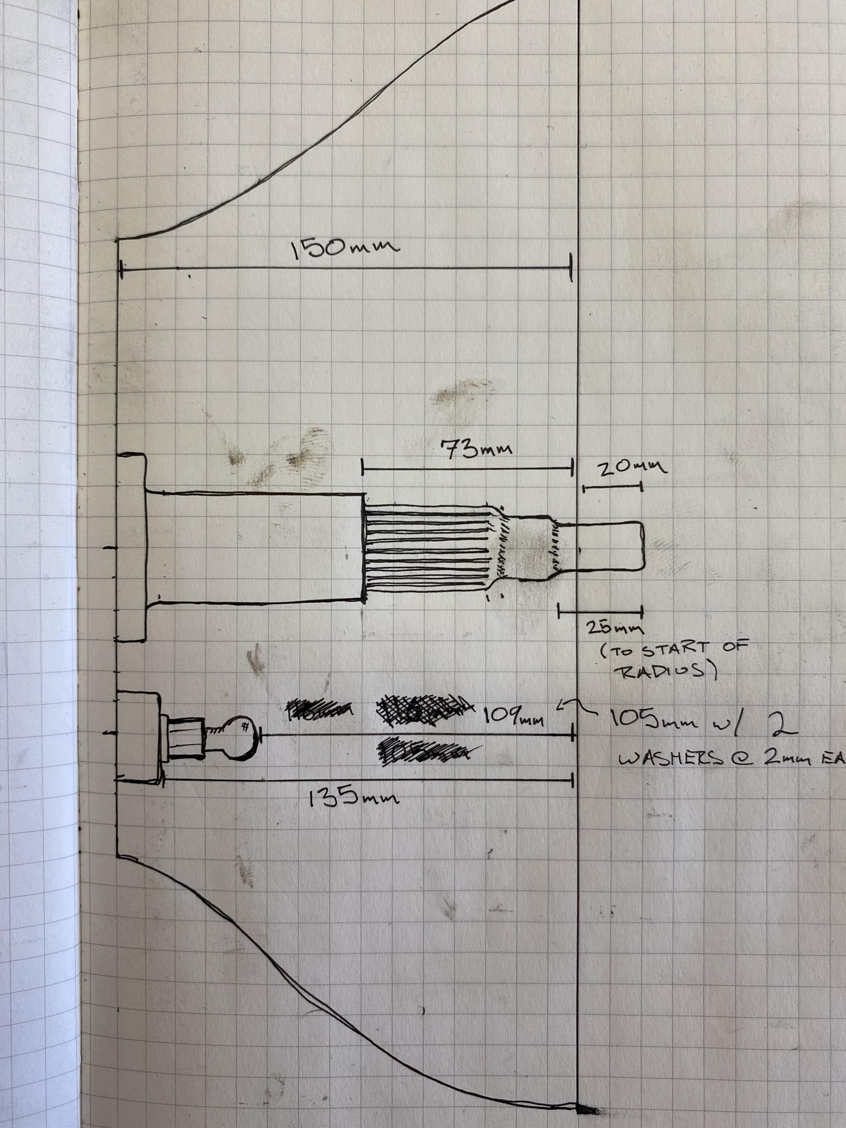
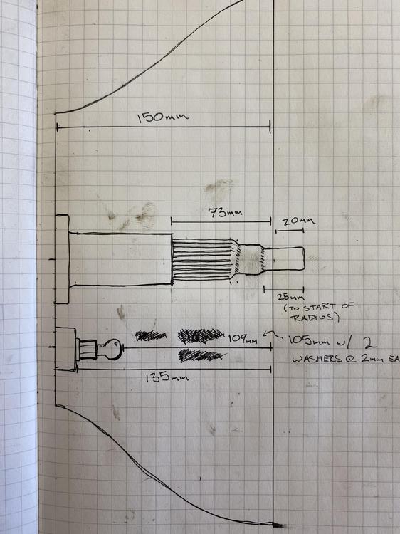
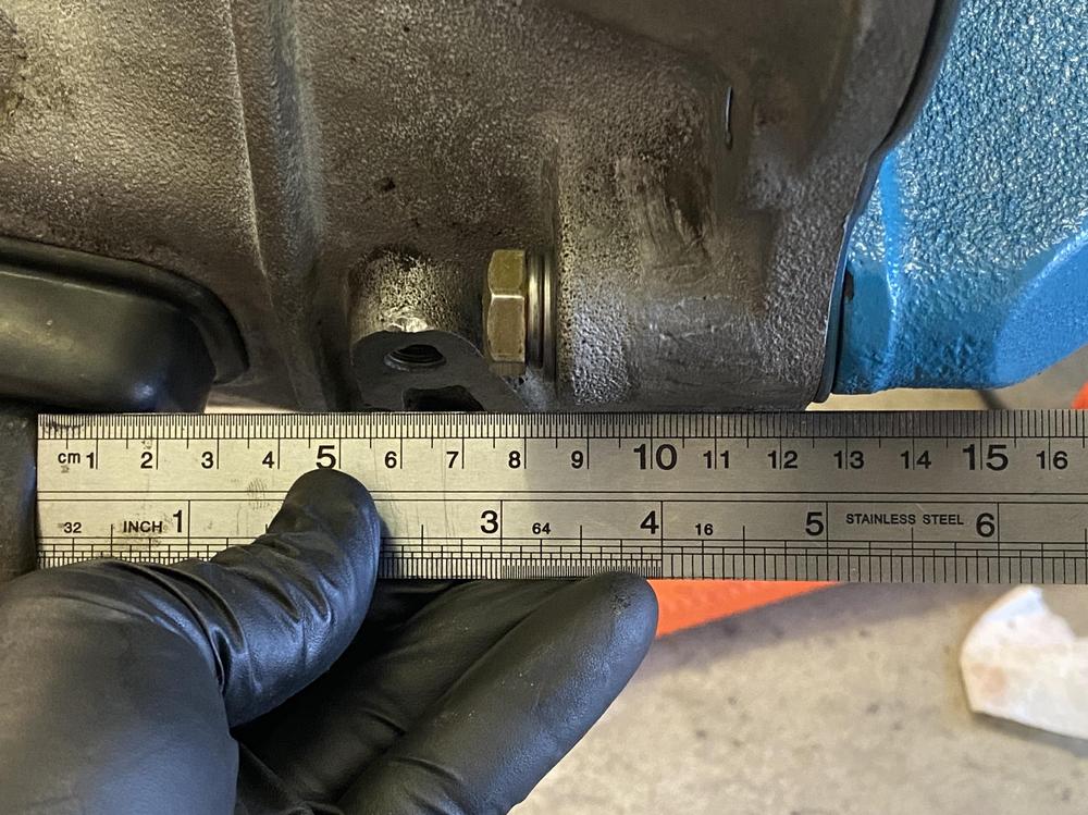
I just pulled off my transmission again to measure this, and I get the same as you - ~135mm to the flat. I remeasured the distance from the transmission face to the pivot, and I now get 105mm with my extra 4mm of washers. I must have made a measuring mistake the first time. I’m uploading my amended drawing below.
-
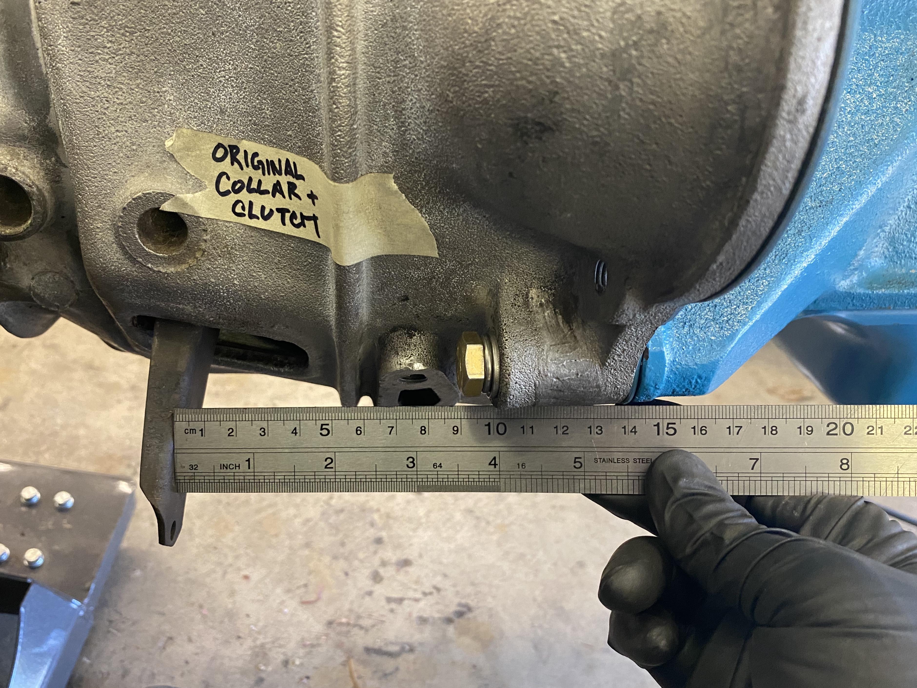
Ok, so that's very interesting - your pivot is only ~2mm taller than mine, however you measure only 105mm from the bellhousing face to the pivot, whereas I have 116mm. I wonder where those extra 9mm are coming from. Looking at the two pictures inside our bellhousings, the transmissions certainly look identical.
-
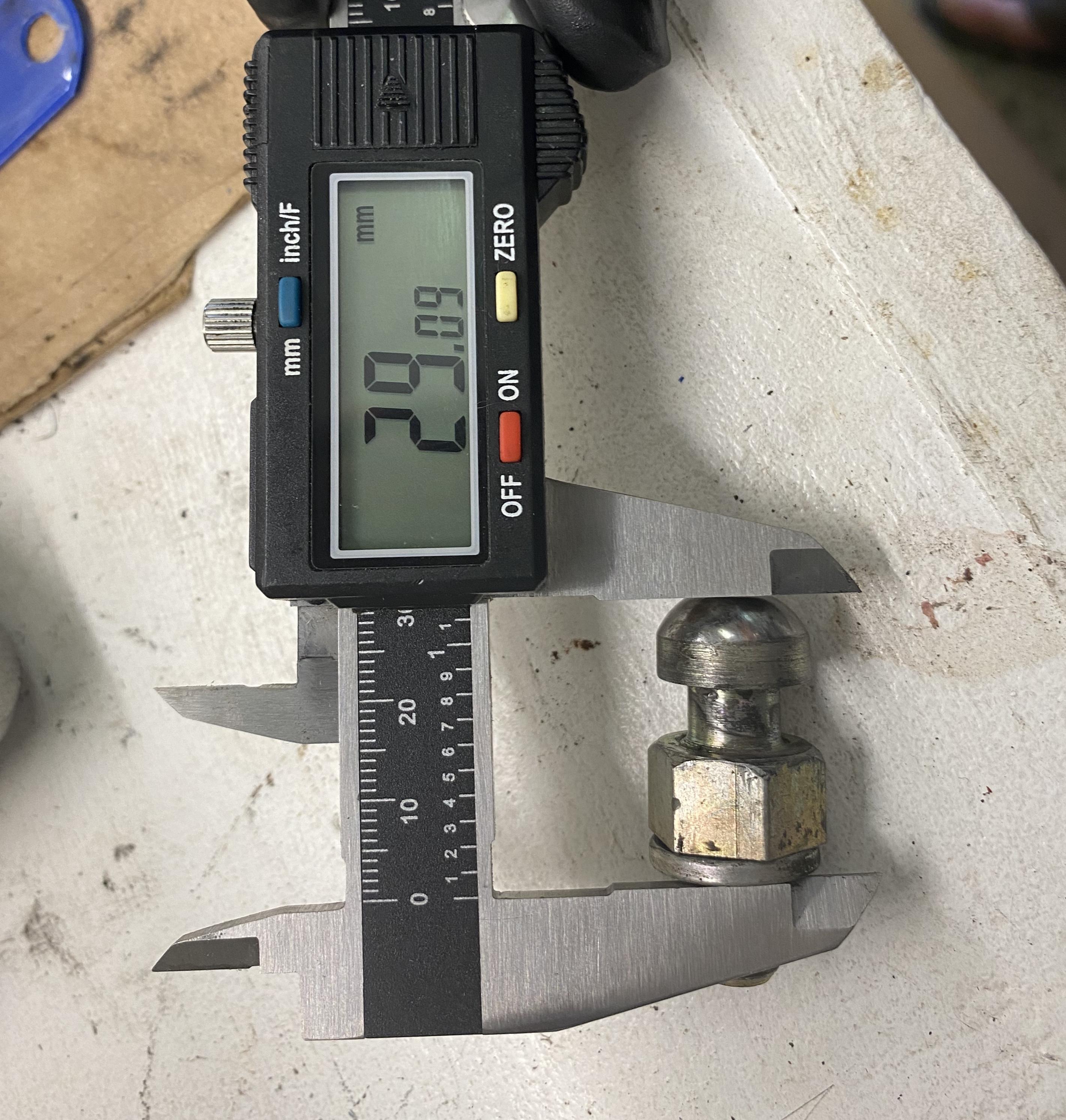
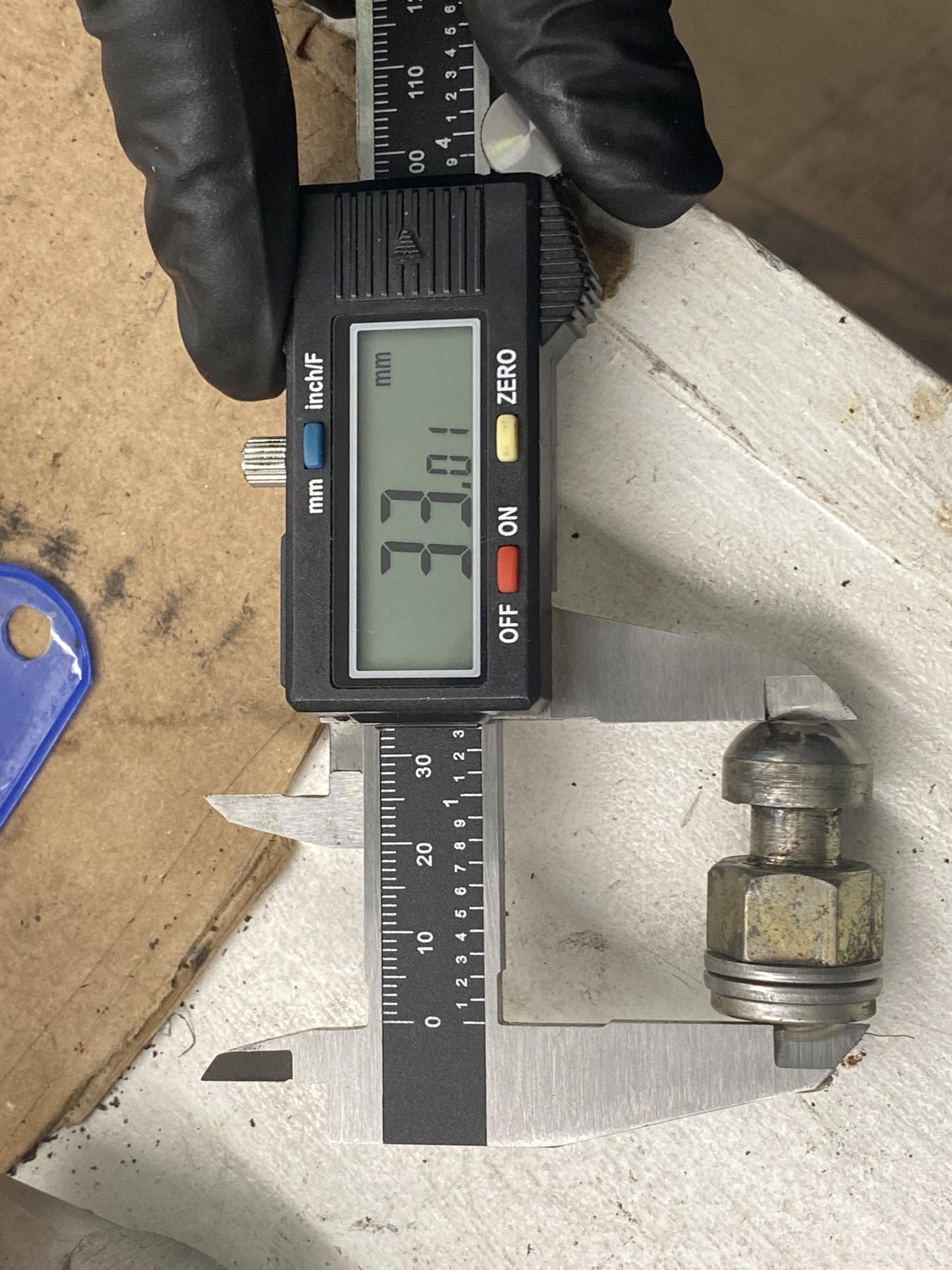
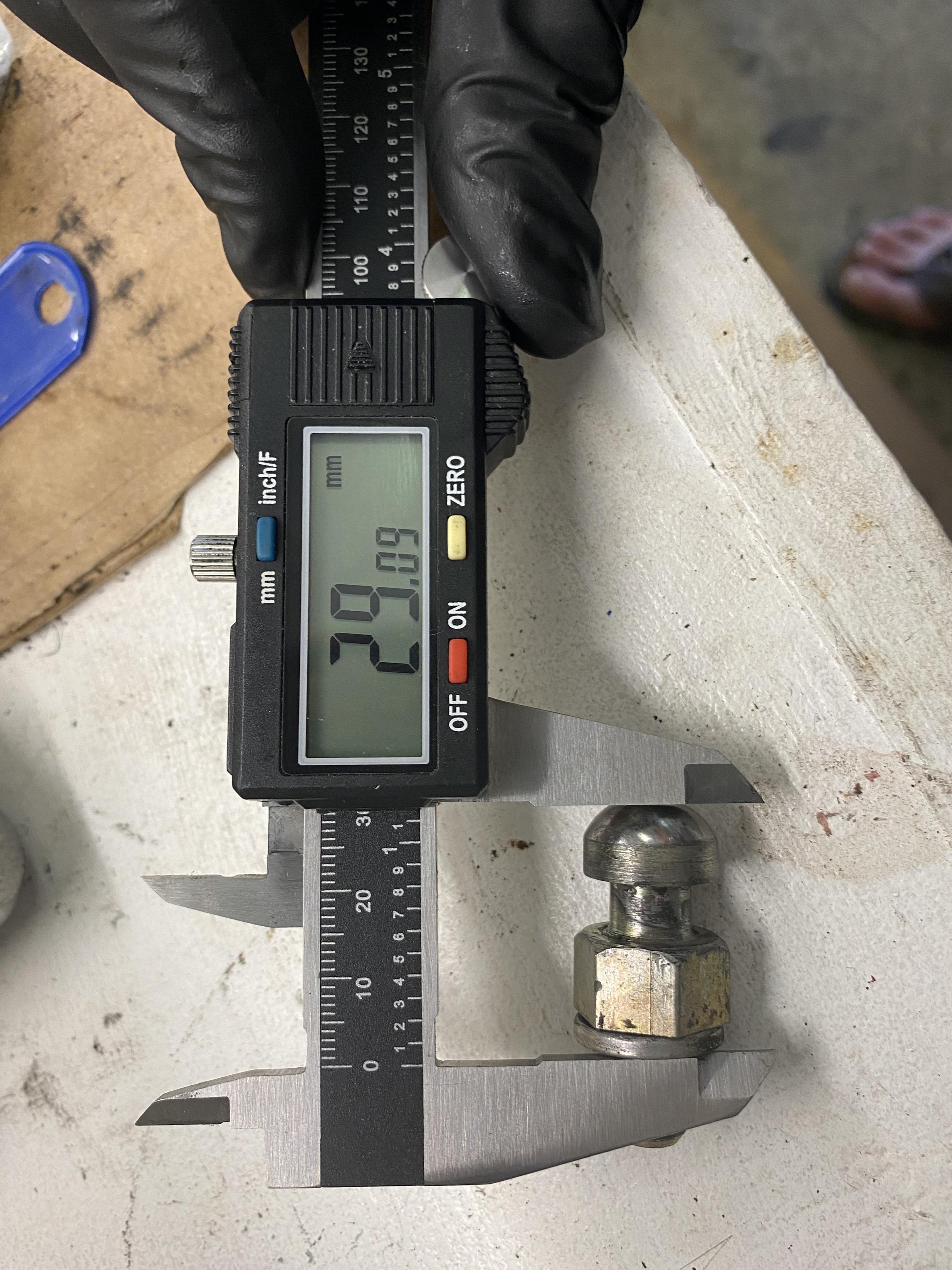
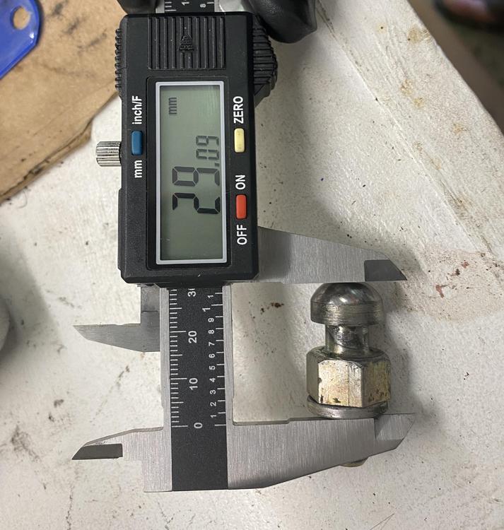
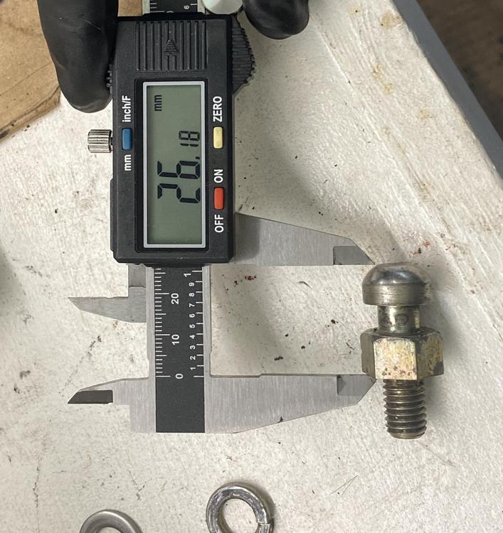
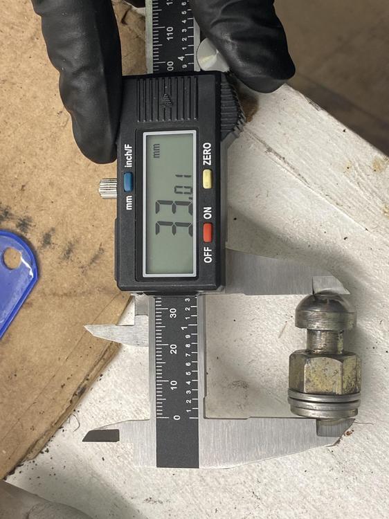
Thanks @240dkw - interesting that you get different numbers than mine. I’d love to trace down the disparity if you’re up for it. Can you measure the height of the pivot itself, from the top of the ball to the bottom of any washers it’s sitting on? Mine measures 29mm with the single split washer it came with, ~26mm without.
-
I did the same search, and couldn't really find anything either. At this point I'm pretty convinced that either the original pivot was longer, or that the original pressure plate was even taller than the standard 240Z ones. I don't have any documentation indicating that the pivot was ever replaced, but that receipt I posted above leads me to believe that the culprit is likely the pressure plate. Can any of you regulars think of any other names that are likely to be hanging onto early 71As that we could summon to this party? I would love it if the answer was the pivot, because I could probably fab up a replacement given the dimensions. A pressure plate, not so much.
-
Probably the right choice
-
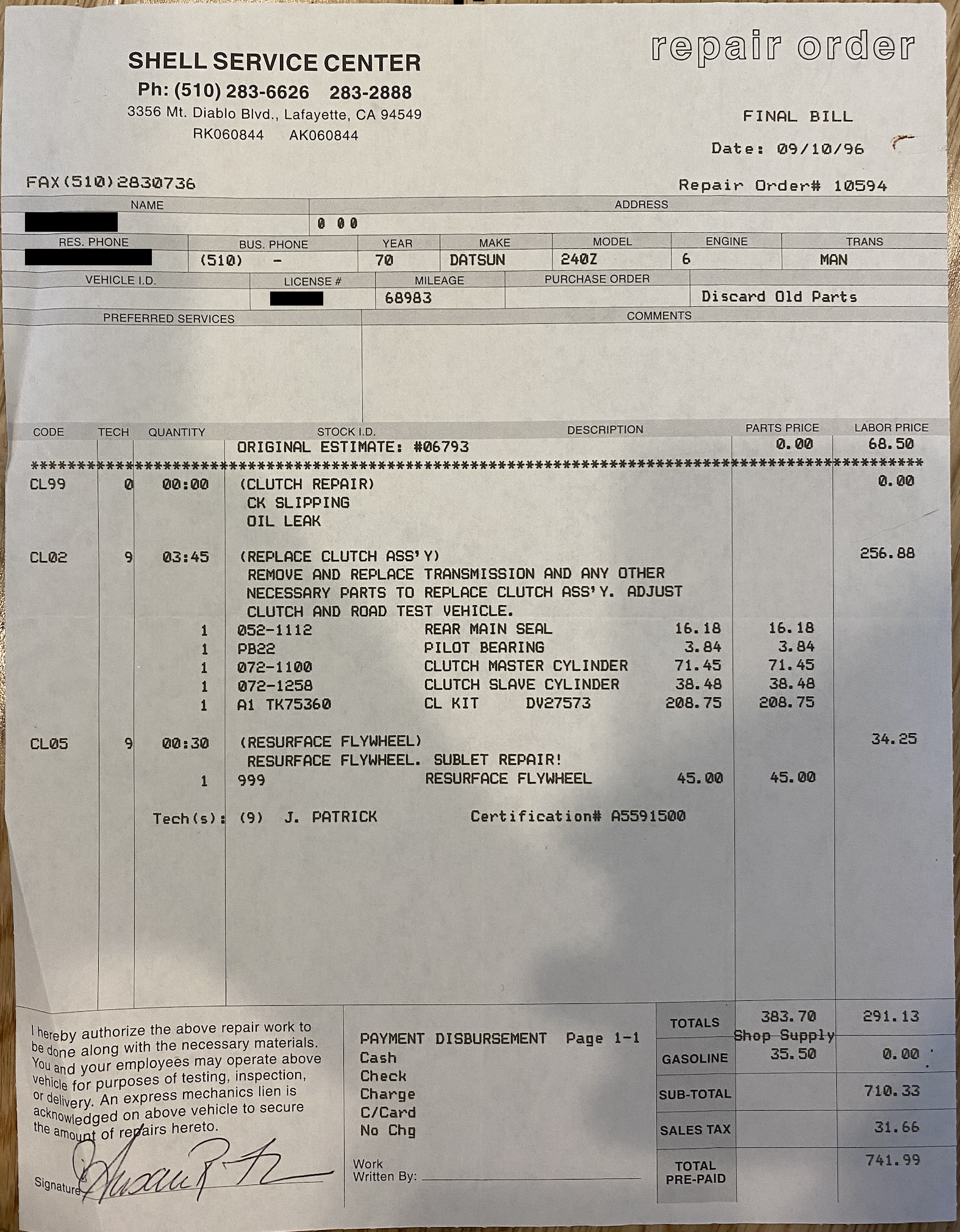
Nice find @Zed Head! My car is 11/70 so it would make sense I would have the early part. Definitely very interesting that it states "no interchange". I dug through all of the paper work that I have on the car, and it looks like the clutch was replaced once in 1996 at a Shell Service Center. Not to knock on the tech J. Patrick, but I'm betting he was no Z-Doctor and may have put in the wrong pressure plate. It would be great to hear from other owners with first year cars to see if their pivot is indeed drastically longer than the later models, or if their pressure plate is significantly taller. Paging @duffymahoney - do you happen to still have the 4-speed and pressure plate you pulled out of your Series 1?

-
@Patcon ah sorry I misunderstood. I think you’re right that the 71B has a plate that effectively raises the height of the pivot. It’s possible that the 71A is just badly designed and always had throw problems, or that it relied on an even taller pressure plate that nobody really remembers.
-
Ok I reinstalled everything with two extra washers under the pivot to give it an extra ~4mm of height. After bolting everything back together (man I’m getting fast at this) the throw feels muuuch better. I don’t quite have 115mm from the fork to the bellhousing, but I’m getting ~125mm which is good enough for me. I’m going to call this good for now and try to wrap up the rest of this build. I have plenty of other scary things to figure out so I’m confident I’ll be back soon. I’ll post an update in this thread once the engine is in just to validate that the clutch is actually working and has decent pedal feel with this solution. Thanks for all the help everyone - I hope someday someone can come up with an explanation that makes sense

-
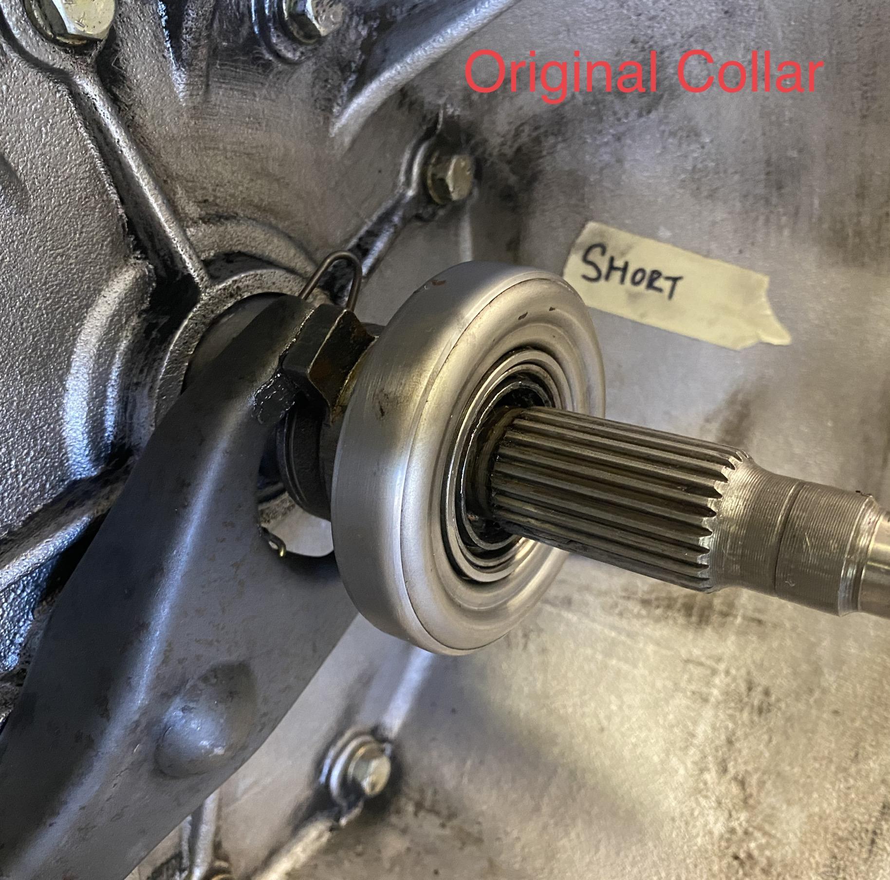
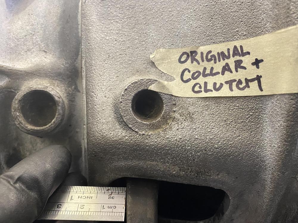
It certainly doesn’t look like there’s supposed to be an extra cover there. I’m not sure what it would fasten to, plus the hole that the pivot currently goes into is already threaded. Having two threaded holes on top of each other would be a weird design choice and would likely lead to cross threading/spreading. Remember, this is a monkey motion F4W71A transmission and I believe it’s the lack of that cover that ZedHead pointed out earlier.
-
I would just love it if that were the case. Here’s some more media. IMG_1636.MOV
-
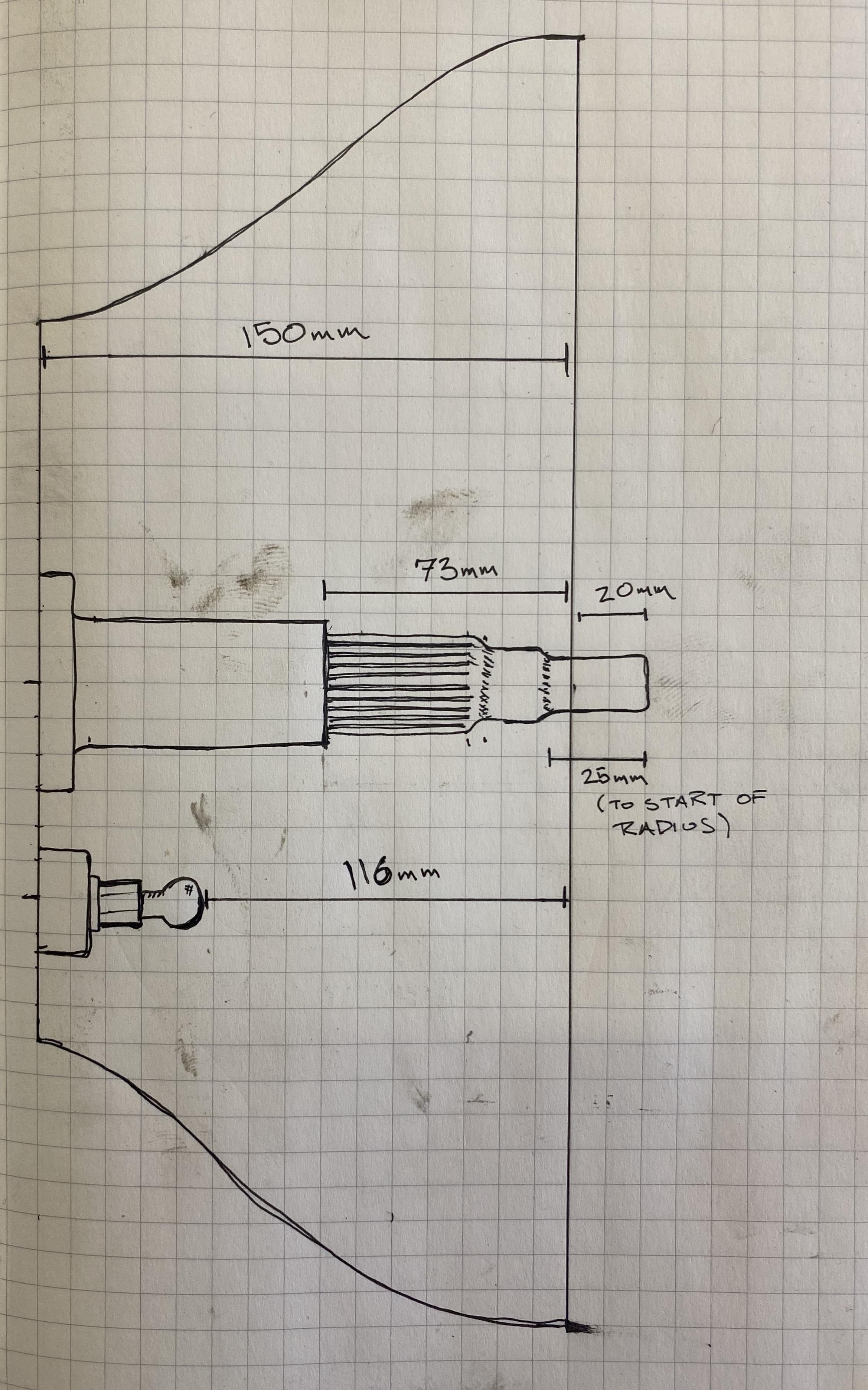
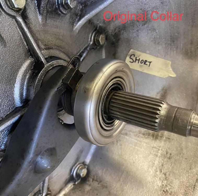
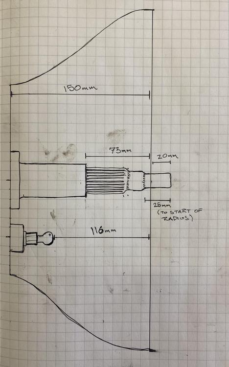
I put the entire original original clutch setup back on this morning (collar, fork, pressure plate, friction disk) and my measurements are even worse! I now measure over 140mm from the bellhousing face to the depressed fork, and have less that 10mm between the back of the fork and the back of the fork window. This means one of two things: 1) This has just always been like this, or at least as far back as anyone remembers. My father-in-law doesn’t remember having any clutch issues, but it’s possible this setup was just barely over the threshold of working. Unfortunately the clutch master seals were dust when I got the car, and it was shortly after replacing the MC that I started down this whole rebuild road so I have nothing to really compare to. 2) I’m doing something deeply wrong with how I’m putting things together, and I’m making the same mistake with the new stack up as I am with the old. I don’t think there’s too much room for error here though, especially with the amount of pictures and videos I’ve been posting. Can anyone think of anything else dumb I might be doing? I made a quick drawing of the dimensions to compare to @EuroDat’s. Interesting that the bell housing edge to nose tip is off by 8mm between out drawings and the bell housing to pivot is off by 13mm. I’m not sure what that means though. I’m going to try shimming they pivot and installing the new clutch/collar again this afternoon. If that works, then I’ll probably just leave it and move on with the rest of this build.

-
You and me both! It's hard for me to get in the garage on weeknights, but I'm hoping to find some light at the end of this transmission tunnel this weekend.
-
Heh a ruler will do just fine. This has been documented in several places, but never with all of the collars at once, and never with the relevant measurement. My diagram [here] is basically what I'm looking for, but with real measurements instead of computer magic and ideally with bearings attached. It's not critical, just something nice to add to the archives if you're bored on a weekend.
-
Any chance I could convince you to take pictures of all of the unique collar types with calipers between the ears and the bearing mating surface? I’m planning on writing a Pulitzer Prize winning novella on my saga and it would be nice to have some good pictures to go along.
-
This is great, thank you - I'll take measurements on my transmission as soon as I can get into the garage and post a comparison to your picture. It's a little hard to see in the video, but the collar/bearing are definitely moving when I move the fork. When I'm flicking the fork forwards you can kind of hear the sound of the bearing "slapping" against the springs. I shined a flashlight in there and watched it move, so I'm pretty confident the bearing/sleeve aren't bound up. There is the little circular retaining "clip" that goes around the collar anyway that holds the fork tines to the collar ears. This keeps the two pretty well coupled so it would be difficult to pivot the fork without moving the collar, right? My nose looks pretty clean, and I didn't notice any grooves worn in it. I'll take some pictures when I grab those measurements to compare to @EuroDat's. I'll admit that I struggled getting the transmission on the first time and tried gently coercing it together by tightening the bolts. I got nervous as the bolts tightened though, so I took the whole thing back off and have since gotten good at slipping the splines in without any mechanical advantage. I don't think I caused any damage the first time - I've been able to take the transmission on and off a few times since without any issue, and I didn't notice any cracking/bending/etc of the nose. I'll inspect thoroughly though and see if anything looks rough. Honestly that's a relief to hear. I'm beginning to feel like I'm losing my marbles with this, so it's comforting to know I'm not the first ?
-
Ah yeah, it's the monkey motion 71A. I probably should have reiterated that along the way. I just called my future father-in-law who gave me this car, and he couldn't recall ever having any major issues with the clutch - certainly never having to stomp the pedal to the firewall to get it to release. I'm assuming that means the old setup is valid, so I just need to figure out where the difference is between the new and old. I'll also try reinstalling the old clutch just to make sure. I've been assuming that the 92mm stack-up height is correct regardless, because that's the number I measured off of the old parts. However, in my 92mm measurements, both pressure plates have been just laying on the bench with the friction disk out of the equation. This discounts any difference in height of the pressure plate itself, and only measures the distance from the throwout ears to the flywheel-side face of the plate casing. It's definitely possible that the difference is actually in the pressure plate itself, which had been hovering above the bench when I measured. I'll do a side-by-side measurement of both the new and old pressure plates sitting on their respective disks and see if there is a difference. I'll also grab a reading of the bellhousing face to the pivot while I'm at it. Any idea what that is for a 71B? The transmission is still mounted to the engine, so I'll have to wait a few days until I have time to spend in the garage before I can do any more work.