
Blitzed
Free Member
-
Joined
-
Last visited
Everything posted by Blitzed
-
Sorry, meant thermal related, spell check ; )
-
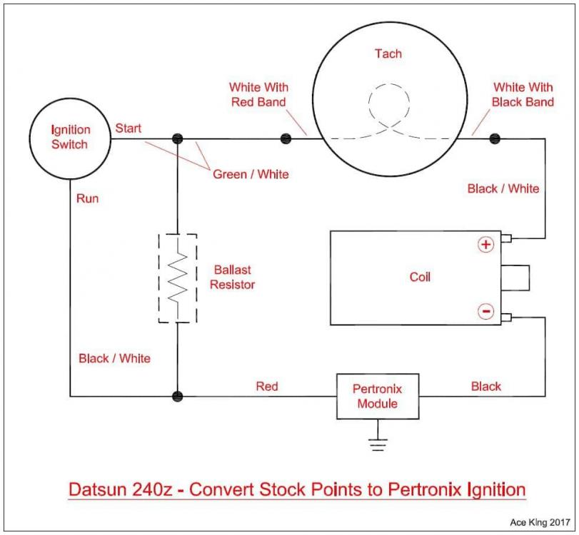
Hi Dutch, Yes, in the process of converting an NA L28 to a modern EFI system and the old girl is fighting me. No the car is not very special yet :). As many have previously done, adding a ECU (Haltech) and trying to not disrupted the existing harness as much as possible. Only four connection points to the old harness, tach, coil (delete wires), ignition wire and fuel pump. Engine starts, runs with the above wiring completed. What I'm fighting is component or components (relays, terminal) creating RFI noise, not good for the ECU connection. The Haltech CAN display in the dash stops working at start up. Could explain this a potential drop in voltage causing the problem, not sure yet. The ECU has a different issue will stay connected for various lengths of time but will discount from the PC (engine will continue ti run). Thinking this disconnect could be terminal related as the car warms up, maybe a terminal switch or relay gone bad???? It's a process of elimination.
-
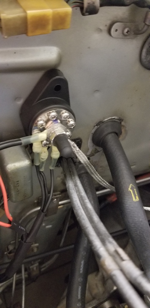
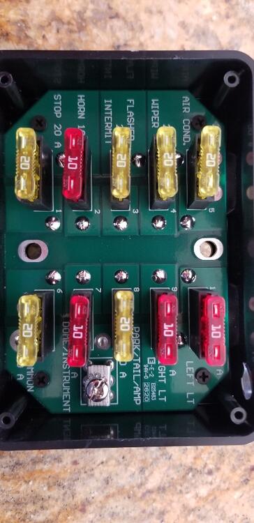
Hi All, Hope all is well. Have a few relay related questions. 1973 240Z late production. First - My passenger side kick panel relay pic is below. Based on the diagrams in this post, the bottom relay is the Air Conditioner relay. I've removed the AC from the car and all switches. What would cause this idle relay to warm up when the engine is running? Second - Would any of the other three relay create noise? tracking down noise near my ECU, pausing. Third - I disconnected the relay on my firewall next to my grounding plate. I can't locate any info on this relay on this site. I found an article on a relay's on later Z's with Hitachi carbs that used a decel type of relay??? Not sure. But when disconnected had zero effect on the car.


-
-
Hi Duffy, Build looks awesome, great job. Working out ALL kinks on my EFI conversion is where I live right now. Our builds are similar but different. Did you experience any noise or magnetic issues messing with the Haltech 750 ECU connection? Running a single HEI coil, sequential fire distributor. All ignition components are resistor style (plugs and plugs wires) and continuity testing proved within spec. Engine starts and runs perfectly but the ECU will disconnect from the PC after a min or so, engine continues to run fine. I can reconnect while the engine is running, same result disconnect. Added a Haltech CAN gauge in the dash the CAN will operate up to 1,000 RPM and then freezes. Will not come back up on until engine is shut off and ign switch is back to the on position. Much like your build the only wire spliced into the original harness is the black/white wire at the ign switch to the pink ignition wire to the Haltech harness. BTW- the stock 240z tach wiring in your log worked perfectly on this conversion as well. Where did you find the screens for your ITB horns? Thanks
-
Hi Zed, Thanks for the info. Yes, new external regulator install 2019, before the ECU went in, engine was running fine and the same battery was installed, wasn't burning through batteries. Maybe over thinking the reading and 15, not an issue? The voltage does changes when running a will drop into the low 14 to high 13 but will also reach 15 number. I'll check out the VR adjustment and take a look at the wiring at the alternator. Thank you
-
Hi Zed Head, From the ECU. The Haltech ECU provides a battery voltage non-run and running engine. Metered the battery with engine not running and voltage displayed from the ECU was very accurate, 12.38 volts not running (Optima Red top). When the engine is running the ECU is showing the voltage moving to 14.70 - 15.1 (red screen at 15+) warning for potential battery damage, ECU provide engine warning signals California car, outside air temp is 85-90 degrees when starting.
-
Hi Steve, Thanks, Haltech CS has been less than helpful. More for the experienced ECU installer and tuner. If they size you up as inexperienced, you're directed to the tech site and on-line support video's. That's ok, my goal is to fully understand the system, wiring and subtle nuances with the L series engine. Better scenario when you find yourself on the side of the road :).
-
Hello All, Need some help with Haltech Elite 750 ECU install, engine starts and runs well with all the new EFI ignition mods. Two problems have come up that may be related, not sure? First - Has anyone experienced the Haltech ECU disconnecting from the PC after engine start or ignition? Also installed a Haltech CAN gauge in the dash at 200 RPM the gauge freezes and reboots with disconnect of the ECU to PC. So I must have electrical noise at start up? Running NGK R plugs (resistor style), Taylor sprio pro wires (made for ECU applications). Could it be the new HEI coil (pic in this post upstream) with transistor igniter that's causing the noise? Cranking dwell setting at 4 per manufacture spec? Second - after the ECU disconnects from the PC engine will continue to run perfectly but the battery voltage is hovering around 15 volts. The coil is star grounded to the head not the battery. The only connection to the battery and coil is through the ECU coil wire and the ECU power wire to the battery. How can test the to see if the alternator is the problem with the voltage reading or not? Thank you for your help.
-
View Advert Barely used 123+ tune blue tooth distributor L24, L28 New / used 123+ Tune distributor for an L24, L28. Less than one year on the engine. Is factory reset for use and the proper oil pump key. Tune functions from your phone and does not impact the functions of your stock tachometer. Can only speak for the 240Z tachometer, no issues, functioned perfectly. Paid over $600.00 delivered, see invoice. $475.00 USPS shipping included to lower 48 only. Converting my engine to EFI, no longer need the distributor. Advertiser Blitzed Date 08/19/2021 Price $475 Category Parts for Sale
-
View Advert 73 240Z Seatbelt Receivers Left and Right Looking for a set, left and right seatbelt receivers with the hard plastic cover. See image. Advertiser Blitzed Date 08/12/2021 Price Category Parts Wanted Year 1973 Model 240Z
-
Bless you friend, a solution. Thank you for the post and help.
-
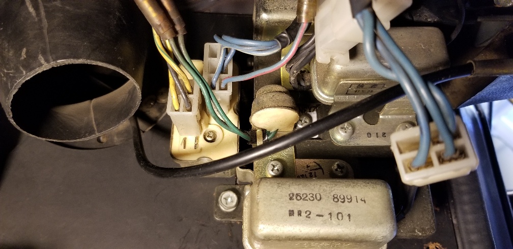
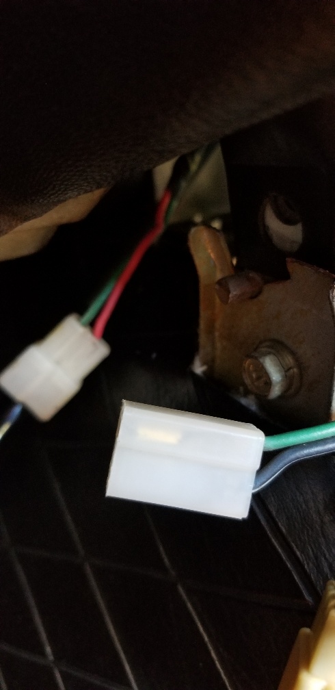
Hi w3wikes, All good data. I've located the connector at the console, no issues there. Sorry, not familiar with the term "jumpering" . How do I jumper the console connector to activate the circuit? my last instructions were to meter the fuse and connector and determined which side of the fuse had the juice. left side of the fuse, no juice. Right side juice, so the connector is not part of an existing circuit. Never received a you're screwed, so just assume so. From another post about relay's on the passenger kick panel , assumed I'm missing components to complete the circuit. Are you suggestion another path to power the connector? Thanks for the info.
-
Hi SteveJ, Yes fuse was pulled but operator error forgot to reinstall the battery ground. Once the battery ground was installed, close to zero (.1,.2) on the left side for the black and white and larger reading on the right side. Green is dead both sides, yes un-terminated wire at the fuel tank connection.
-
SteveJ, Hope all is well. With all reinstalled and connected. Key in the off position. The green wire is dead from both side of the fuse holder. The black / white has continuity from both side of the holder. Right side registers a larger number .19 on the meter left side lower .12 ???????
-
Hi Patcon, Will do as soon as the fuse box is reinstalled in the car. As with most hunt for the unicorn it requires access to the harness. Assume this fuse box will carrier the same fuse location to check for continuity and same side of the fuse?
-
Hi All, See relay pic. Only four relays on the right side kick. Car is documented as 73. Had the square rear sway bar mounts on the sub (no bar), so would assume late production. Thank you,

-
Hi cgsheen1, Thank you for the response. So in the simplest answer yes or no. On a non factory fuel pump 240z. Did Nissan just run the wires and not complete the connection to the ignition? Lose connector at the console. If not complete, did they provide another factory connector at the console to plug into or do I need to run additional wires to the ignition to complete the circuit and power the pump? have a FSM but wiring diagrams are a mystery to me. Thanks for the help and safety advise. Will purchase the switch.
-
Hello Zed Head, Thanks for the info but did not satisfy the question. Found the info on the second connector, fog lights. Will not put them together :) So anyone who has added /installed a fuel pump to a 240 (not previously installed), please respond. Found the connecter and proper wires at the console. The connector is not plugged into another terminal. Where does it connect? No power with key in start position as it is a lose connection. Thanks you
-
Hi All, Searched "Help Me" but came up short the specific answer. 73 240Z non fuel pump version. I'm installing a fuel pump and stumped on the factory wiring config at console. Black and Green wires at the tank - Wires are there, all good Black/ white and green under the console - Found them, see pic The Black / white and green connector has never been connected to anything in the harness. Looks brand new. The only other connector not connected (same style 2 pin connector ) has a black /yellow and red wire (background of pic) and appear to loop to the fuse box. Could just put them together and wait for smoke and flames :) Need a confirmation on this connection or another location. Thank you.

-
-
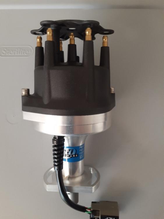
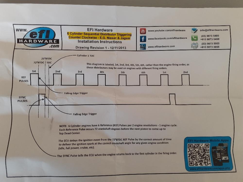
Thanks for the info. The config attempting to set-up is not unusual but not the choice of most. The hall effect distributor purchased (new in the market) will allow the set-up to start with a single H.E.I coil, sequential fire distributor, easier to convert to EFI but for some not the most efficient (this is not a race car, drive). See distributor pic and hall effect signal provided by the unit. The nice option to this distributor is the ability to remove the distributor cap, install a distributor cover and run a distributor less coil pack or COP set-up in the future. First ECU install and EFI conversion so the leaning curve will be a single coil and sequential fire. Rotor phasing is complete (not test) dwell will be a programing function through the ECU. Apologize my initial post was about wiring in-line with stock harness as with new products /conversion you end up going down different paths.
-
Hi All, Correct, ignition module required. The HEI coil pic in this post has a 3 pin igniter/ ING module (blue dot on top) integrated. All of this is straight forward, wires coming from the ECU and neg from coil. My concern is eliminating a connection from the existing harness at the coil and ballast resistor. Thanks,
-
Hi SteveJ, It came with a wiring diagram for the new components. The more I talk this through or over thinking it. There are really only two connections from the stock harness. ECU to the IGN switched 12v (key) and connect the black/white on the positive side of the old coil to the positive wire on the HEI coil, should be good. There are no points so the negative (black wire on old coil) side of the coil is eliminated. The ECU will ground the igniter and coil. All other connection remain the same. New new coil requires an igniter wired through the ECU and connects to coil, the new distributor wires directly through the ECU (no connection to the coil other than the coil plug wire to distributor cap). All other sensor have assigned wires through the ECU. Will just keep the stock ballast resistor and connections in place. Not sure if they're needed or function but it can't hurt? I guess :)
-
Thanks Zed Head and Steve J, Still a little confused but getting closer to really confused, how I like it. Ign switch: Based on the response I should spice into (and not remove) the switched 12v ign wire from the Z harness. Too much going on down the path. The Haltech wiring harness has a fuse box and the ECU ign wire will be covered by this circuit. Coil and resistor wires: Not concerned with the existing tach wires, will try the ECU/tach conversion provided by Duffy using the existing stock 240z tach internals . Splitting the white wires and running white/red through the ECU and white black to coil +. Sounds the solution to the old Z tach internal. Still concerned with what to do with the coil wires / connections. The HEI coil has a external suppressor (see pic), single pin connector. Does a coil suppressor function the same as a ballast resistor? Thank again,