
Blitzed
Free Member
-
Joined
-
Last visited
Everything posted by Blitzed
-
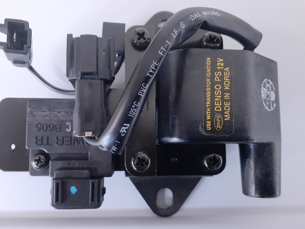
Hello, Have a few basic questions about installation of Haltech Elite 750, 73 240Z NA. Overlaying the Haltech wiring harness to the existing 240Z harness, can't get my head around some of the connections. First ignition wire (Key switched 12V) Which wire on the 73 240Z ignition switch is the switched 12v (on) ? (B.Y., B.W, W.R, L.R, or G.W) I have a FSM but not an expert on wiring diagrams. Terminate the existing ignition wire in the connector and replace with the ECU ignition wire or splice into the existing wire and leave it in the connector? The configuration is not typical and information is limited at best. Running a single HEI coil to a hall effect (reference and sync single) sequential distributor (cap and rotor, plug wires to SP). No coil pack (waste) or COP set-up. See coil pic. Second coil and resistor question. If I look at the 73 240Z wiring diagram (from ignition switch) B.W, and G, W connect to the resistor. Correct? Do these wires connect to any other components? B,W from the positive side of the coil connects to the tach, Correct? any other components ? The black wire on the negative side of the coil terminal, does this wire connect to or drive any other component in the existing harness? My concern is wiring the new coil directly to the ECU harness and terminating the wires from the (ignition switch, coil and resistor) will this termination impact other components in the existing harness? Any help would be appreciated.

-
-
Re: Haltech 750, premium harness/ 240Z What is the consensus for mounting the ECU and wiring harness location? Laid out / grouping wires and most for my application (L28 NA ITB) route to the left of engine compartment. Power / grounds for the ECU and fuel pump wires are the only wires traveling right and back. Anyone punched through the firewall just left of the hood latch cable grommet? Any issues with this location? Thanks.
-
-
-
Duffy, I purchased a distributor that provides two hall effect signals (CAS). Running a distributor cap and plug wires, no coils. https://www.efihardware.com/products/1752/distributor-full-sequential-for-Nissan-L-series-6-cyl Just want to wire the ECU to the ignition (on and off with key), distributor and coil (coil to the distributor). just the ignition for timing and advance curve tuning. Thank you for your help.
-
Hi Conedodger, Thank you for the response. As mentioned, sensor's are not the concern right now other then the CAS signal. Want to focus on wiring the ECU to the ignition only, for ignition and advance timing. The coolant temp, O2, TPS, MAP ATS will all be installed with the ITB's and the fuel management. I can loom Haltech wires/ harness those sensors for future install. A quick drawing of the haltech ECU connection points to the ignition, distributor (CAS) and coil would be assume. Sorry DA when comes to electrical schematics
-
Thanks for the response, Any wiring diagram or help you can share on wiring ignition side? ECU connected to ignition, CAS signal and coil wire set-up? Read your post on the tach conversion to your ECU, so would have assumed you've run down the wiring issues already. The tach is not my concern right now, purchased a 77 tach with the post style (negative coil terminal) internals. Will swap the tach internal at a later date. Thanks again.
-
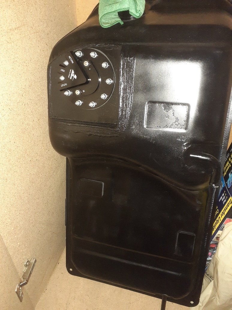
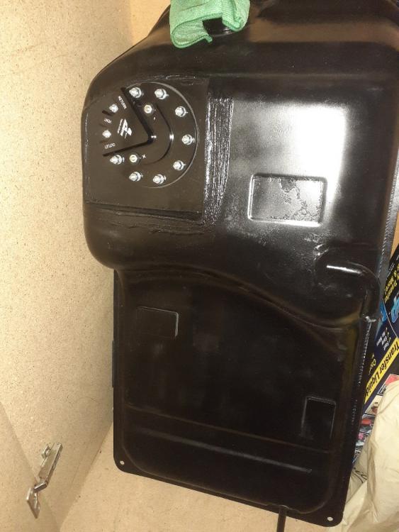
Hello Duffymahoney, Headed down the same path to EFI with a Haltech Elite 750. Accumulated parts over time, to mange the overall cost of the conversion $$$$$. Learning as I go but wiring, blending to the stock harness and fusing the system is a huge grey area for me. early vin 73 240z with a transplanted L28, N42 Block and head, round top SU's. No head work has been done thus far and a stock cam. My goal is to work out the bugs on the modern EFI conversion first (while the car is running and driving) then pull the engine for rebuild and head work and cam. Nothing radical. Convert in stages with a running / driving the car. First convert the ignition. I have the Haltech 750 unit and purchased the modern CAS signal distributor (link below). This unit can be installed with a cap and rotor or as a distributor less coil set-up. Gives you the flexibility of both options. I'll run the ignition with cap and phase the rotor. https://www.efihardware.com/products/1752/distributor-full-sequential-for-Nissan-L-series-6-cyl Confirm with Haltech the compatibility of the CAS signal from this unit. Question- what Haltech wiring harness did you purchase (or not) and how invasive to the stock harness is the ignition (only) conversion? All I want now is ignition tuning and advance curve set -up. Second phase - ITB's install and fuel management. My 73 came with the factory fuel pump wiring (at the fuel gauge sensor) but was fuel pump delete from the factory. Have a new cleaned and sealed stock fuel tank with an Aeromotive stealth in-tank fuel pump fabed/ installed, all the fuel filters and external fuel regulator. Waiting to purchase the ITB's. Thanks for any help with the Haltech ECU wiring to the stock harness, CAS signal and coil. I'll worry about the other sensor later, Map, coolant temp or head and O2.
-
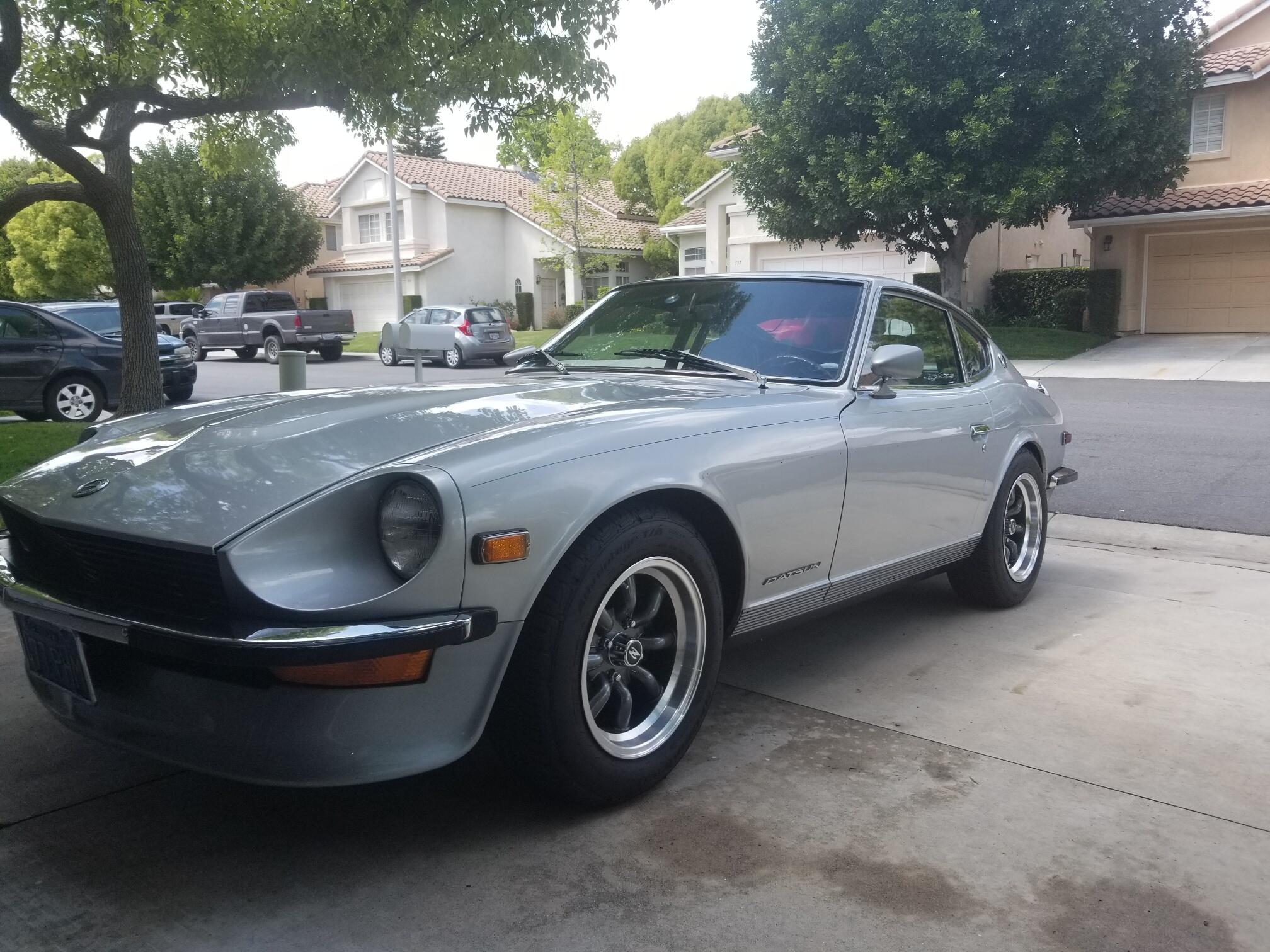
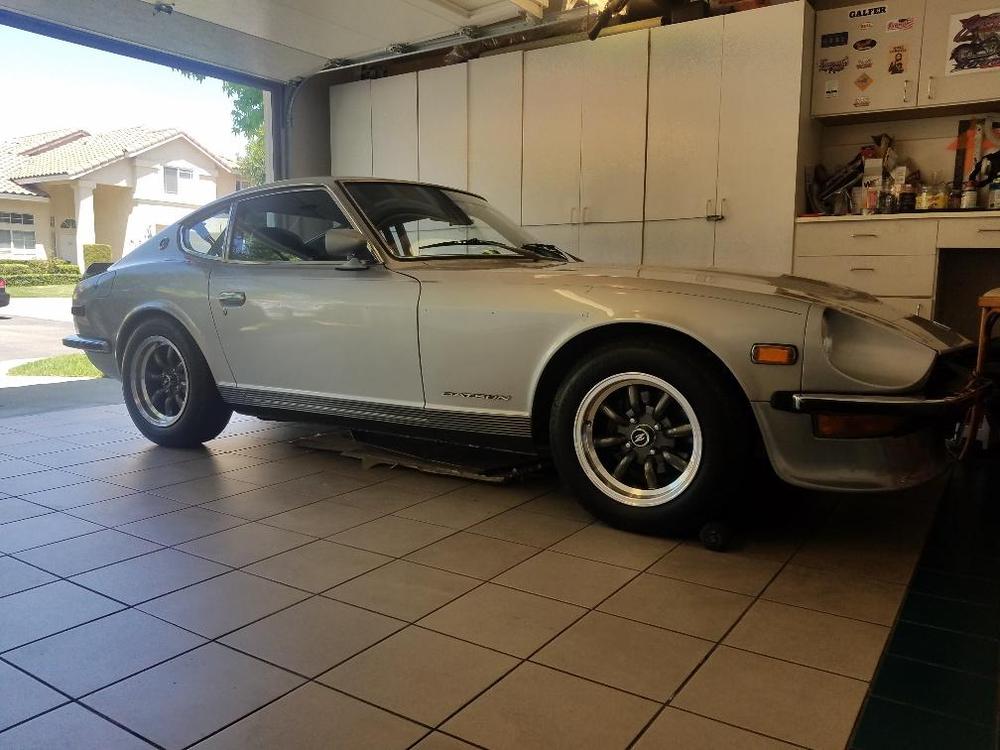
Great choice! Tire fitment looks good.
-
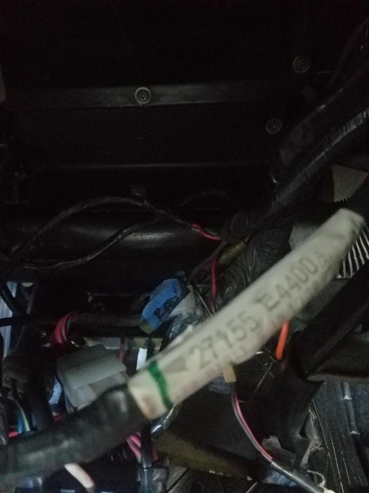
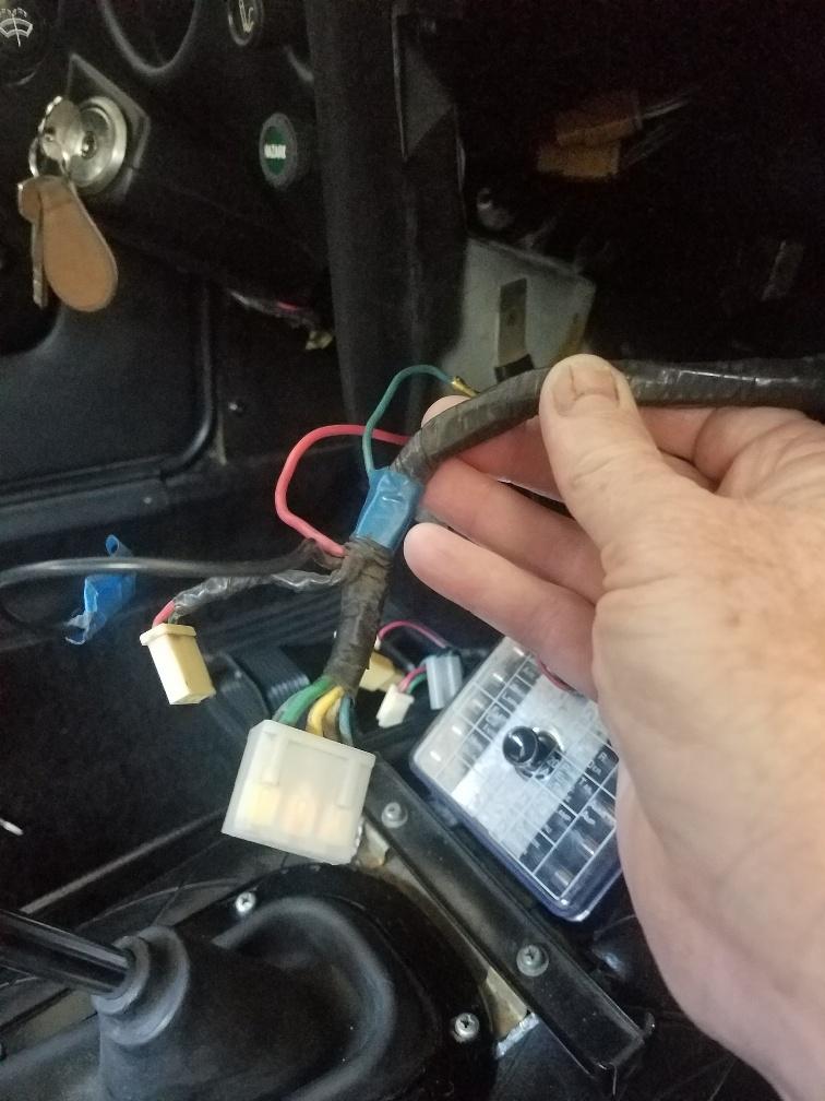
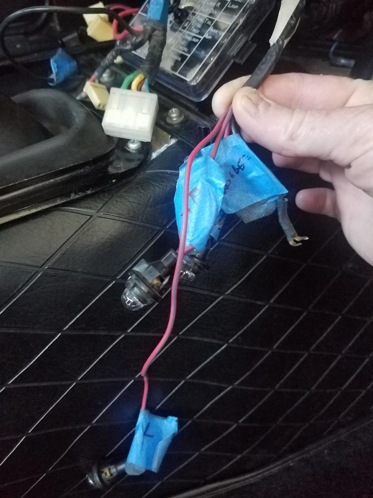
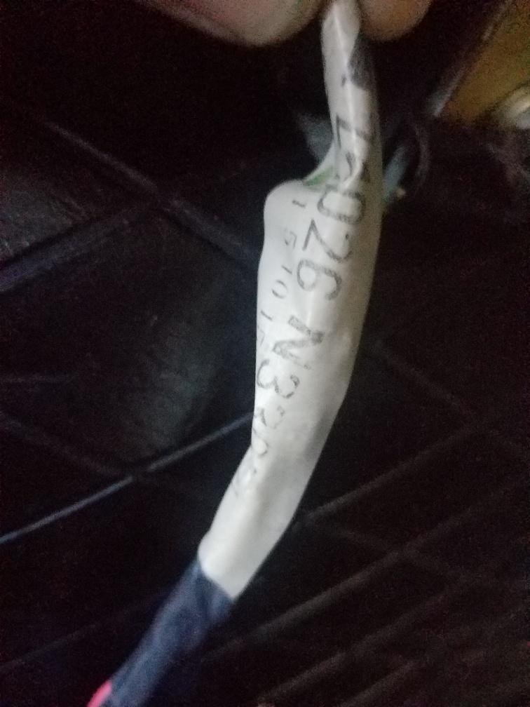
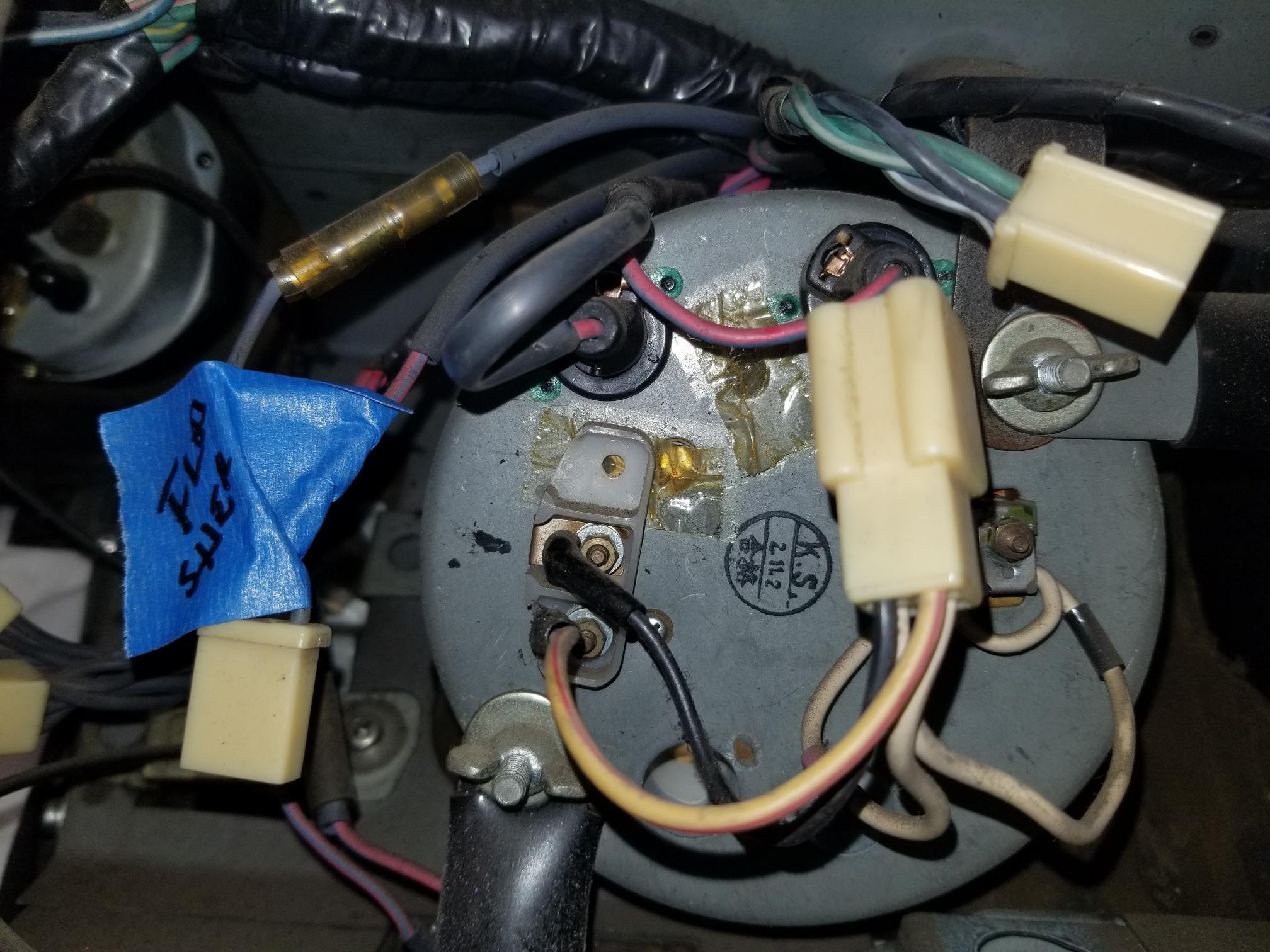
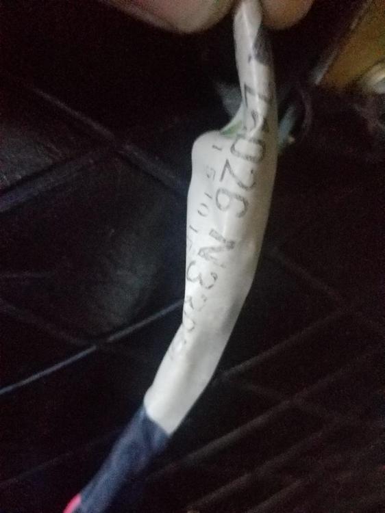
Hi All, Finishing up the re-connecting of wires from my dash restoration. Want to be sure and double check before I button it all up. Car runs no, issues to this point. Have the same wiring harness part number as the start of this post 21755-4400 (73 240Z). See attached. Connects to blower motor and blower switch. The ground (black) coming off this harness, I had marked as radio ground. Like a DA didn't take a pic of where this ground wire would have attached to the stock radio. Is it as easy as pick one of the mounting screw on either side of the radio to ground? My FSM is delete of a radio wiring diagram. Also harness number 24026-N3300 carries the three small panel lights (fan switch and heater/vent controls) in the dash. This harness also includes a black ground. I marked as console ground. Again DA no pic upon removal. Where is the this ground mounted? (back of the fan switch plate?). Thank you for your help.


-
Hi Sean, Thanks for the details. Too late for my project now, maybe in the future. Went back to the 240z tach using the stock harness. The dash restoration looks great back in the car. The swap of 280z parts into the 240z tach can is pretty easy, where the original post falls down is whats next? Converting a 280z tach that uses negative coil post signal on to 240z harness receiving a signal from the positive post coil signal, doesn't work. Maybe why the post stops after the parts conversion, too many variables/changes and components to add to get the 280z tach to function with the stock 240z harness. Started the tread with the comment, "converting the tach now for future ignition upgrades". Stock distributor (with pertronix upgrade) and stock coil, tough to accomplish the conversion without a adding and changing a bunch of the stock wiring and ignition components. Not as easy as running a wire the neg side of the coil. Engine is coming out next month for a rebuild, will revisit the tach. Thanks again for the details.
-
Sorry tach pic

-
Thanks Zed Head, all good stuff. Even if I owned a meter wouldn't know how to use it or understand the numbers. So this project is over my head. Dash is hung in the car, would like to leave it there moving forward. All previous electrical issues were all caused by the hazard switch. Reversed the wires in the small can in the dash and turn signals, brake lights are all functioning perfectly now. Didn't realize how critical this switch is to bunch of functions. Tach is the only challenge. Understand your concerns about the wires. The dash wiring harness is untouched, zero splices, additional electrical tape or butt connectors anywhere, including both side of the firewall. Pic attached shows the tach wiring from the functioning 240Z tach (prior to removal and swap). So if it functioned with this set -up it's safe to say power is power and ground is ground. Followed the instructions with the internal swapped and reverse the wires per the harness on the 280z tach and internals. The 280 tach I swapped is exactly like the tach pics in the instructions above (ground and power reversed). So let assume that's correct. Ran a wire from the post directly to the negative side of the coil, the only measurement I can give you, it's live. as I grab the connection while the car was running. So current could be the issue with the tach not working, can anything be added in-line to the coil/post wire (the only wire I can touch with the dash installed) to reduce the current?. Sure this rambling drives electrical engineer's crazy. Thanks for all the advice.
-
Hi Zcarfever, Just replaced the tires on my 240Z. Received a ton of advice on the site. Landed on 205 60 15. The 60's fill the fender well nicely. You lose a little patch width with the 60's, no rubbing issues front or back. Pic attached.
-
Hi Zed Head, The 240z tach with the wire loop worked fine. The 280z tach internal swap into the 240 can will not work. Not sure how to clearly express it. Needle does not move or pulse when the car is running, turn signal lights in the tach do not work. The only thing operating on the tach are the dash lights (in the gauge in- line with the dimmer). Duffy Mohoney - please explain coil on the plug. Don't see this in the conversion post attached. Using the stock 4 pin connector with the white wire loop still intact in the connector (coming off the back of the tach) In the connector coming off the tach (female), which pin is coil? The current black ground, white/red power and the white wire loop in the other positions. Thank you,
-
Hi Zed Head, Hope all is well. The work on the Z is very fluid right now, work happening in between post. Purchased a used 280z tach. Followed the instruction in the post to swap into a 240Z can. No additional mods were made. Using the 240Z wiring harness and original 4 pin connector. Ran a wire from the 280z internal post to the negative side of the coil, per instructions have power in the wire. Tach will not operate. Turn signal lights do not function but hazard lights function (arrows on the tach). Moved one of the hazard switch wires (2) into the alternative input hole (3) in the can (in the dash). Now the headlights and brake lights all work. Only thing not functioning are the tach and turn signals. Progress.
-
Hi All, Hope all is well. After sending the "tach not working" post last night, searched the archives on the site, may have touch on the electrical issue. Another lesson in too many changes at once! The original 73 240z hazard light switch broke, the center wire on the knob post broke off (plugs into the small can in dash). Purchased a used hazard light switch from the same reputable source in AZ as the tach (and untested). So the turn signal and brake light issues can all be related to the replacement hazard switch, yes? While the dash and wiring are in the car intact, would like to test if the issues are related to the replacement hazard switch. The small can in the dash has three inputs holes for the two wire plugs, center seems to be static. does it matter which input hole for the second wire? Anyone experienced the issue with the post wire breaking and can it be repaired? broke at the back end of the post, can't solder a slice, not enough of the original wire exposed at the end of the post. Wire appears to travel into the steel post and is crimped at the knob end. Would like to repair the original and test. Tach is still not functioning, all conversion steps have been confirmed and reconfirmed . Without a clear method to test the tach internal function, assume the 280z tach internals are the issue. Will re-install the 240Z internal and live with the tach as is. Thanks for all the info.
-
Hi All, Well the dash re-instillation did not go well. Dash will be in and out of the car for a third time. Sorry for the lengthy response but I have compounding issues now. The 280Z tach conversion into the 240Z housing did not work as listed above. Tach needle is not moving, thought a missed a step so removed the dash/tach and covered all steps again, second re-install, tach needle is not moving. Worst case scenario, my concern from the start no way to test the function of a used tach before turning the key and praying it will work. Purchased the used tach from a reputable source in AZ but they do not test used parts before shipping. So I'm searching for another 280Z tach. Bigger problems now. All the cars electronics functioned well before the dash removal, now electrical issues. Turn signals - Do not operate. No green arrow lights and a single weak click (right not left) from the TS relay (can under the drivers side) then stops. Can I assume the lights not working could be related to the tach not working? Will the tach not working effect the TS switch? Hazard lights function - green arrows on tach light and relay clicks fine from the passenger side. So I know the lights on the tach function. Brake lights - Do not work now. Headlights- Worked before the dash removal and worked upon the first re-install, turned them off, they will not come back on. Running lights -work fine. All dash gauges / gauge lights (including the tach), clock, emergency brake light and high beam light , dimmer, and interior lights work fine. Car starts and runs fine. Will a short in the system begin to take down relays? Have a FSM with a 240Z wiring diagram (no electrical experience), it's great I can locate colors of wires. What I need to understand is where the connectors/connections located? Any advise would be appreciated.
-
Hi All, So I'll be the test rat, replacement 280 tach internals can be obtained. If the jump wire is installed (with the tach and dash out), is there a method of testing the tachs operating function to ensure it will work before painfully re-installing all components turning the key and praying the needle will move? ZCLOCKS - Your 20 mins from my home. I can send the tach to you with the jump wire change made (complete in the 240z housing). Can you test the function/compare to unchanged 280 internal? Or are there to many other variables without the ignition circuit in-line to consider a function test successful? Goal - make all these little changes under the dash before re installation to support future ignition upgrade. Thank you for the advice.
-
Hi All, Thanks for the responses. Sounds like this is uncharted waters with the 280Z tach internals. Was hoping for confirmation. Again, the goal is to make all the changes / upgrades under the dash while it's out of the car. Yes, this is not the norm, but the norm appears to be a tach that is very unpredictable in function when adding ignition mods. Adding components to the tach lead often is the fix. Any other suggestion / upgrades to the other gauges or switches? All are original to the car, including the radio. Thanks again.
-
Hi All, Hope all are well. Pulled the dash to restore the heater box / heater core, replace heater hoses, clean and replace all vents. Clock was not working, sent to ZClocks. While the dash is out like to updated the tach for future ignition changes/upgrades. Purchased a 77 280Z tach and replaced the internals into the 240Z housing, per instruction on in this post. Has anyone performed this resister jump on the 280Z tach internals? https://www.youtube.com/watch?v=Q5plL3aZbzA First question, once you add the jump wire do you remove the 5 ohm resister? Limited electronic board experience, assume if the resister is still on the board wouldn't it still draw current? Second question assuming the jump wire takes the 5 ohm resister out of the coil signal, what potential issues can this cause with the stock set-up listed below? Reason for doing this now with the dash out, never want to remove the dash again or try and remove the tach on my back. Understand some of the ignition upgrades have internal signal reducers which impact the tach's performance. 73 -240Z, L28 N42 head and block, round top SU's. Current - stock distributor, Pertronix upgrade, stock coil. Future - MSD, matchbox or other. Any other upgrades / advice to other dash components are welcome. As mentioned this will be a one and done dash removal. Stay safe and well.
-
Thanks All, New SS rear flex brake lines and emergency brake mounts (for the Maxima caliper) are on the way. Pissed I'm paying for this work twice. Need to replace the rear hard SS lines going to the frame mount. Previous caretaker of the car used vise grips on the fitting (left and right). Are the only options to buy a complete set of SS hard lines ($350.00) or make them? Any suppliers that sell the SS hard lines piece by piece? 73 240Z Making option: what dia SS line is needed and what is the flare fitting tread size and pitch? Thanks again.
-
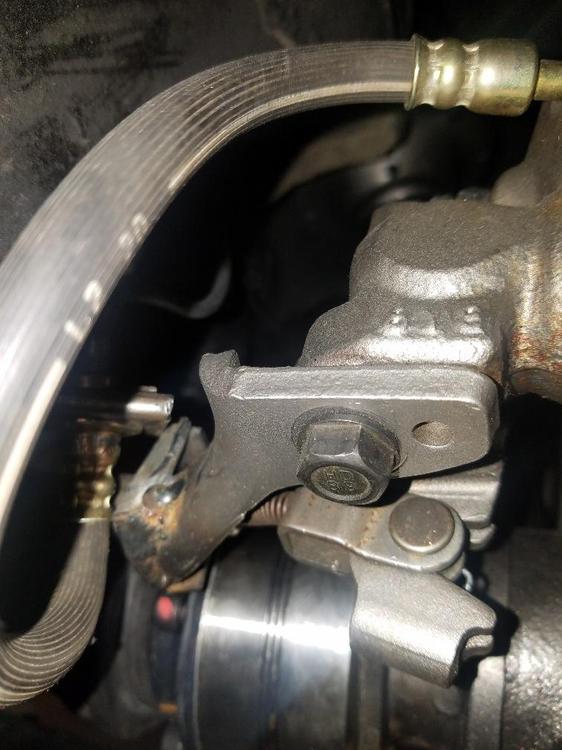
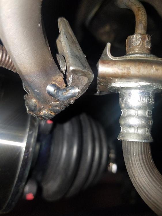
Hi Grannyknot, Thank you for the advise and images, never considered the caliper position. It appears the shop, re-purposed my old drum flex lines with new fittings may be why the caliper is in the 10:00 clock position, shorter brake lines. They fabbed a emergency brake cable mount welding the end mount (clip to hold the cable) from the old drum EBC set-up . These are the tack welds you're seeing in the photo. Since I didn't procure the parts and have zero instructions to the conversion. Two questions: Is there a preferred rear caliper position on the rear rotor for braking performance? 10:00 versus 1:00? They crossed over the emergency brake cables (original stock) above the diff. Was this to make the cables shorter to fit to the calipers? Or a common process for the disc conversion? Thanks again.
-
Hi All, Had a service provider preform a rear disc brake conversion on a 73 240Z. Basically the stage one kit from MSA. Maxima calipers with 280z rotors. Before the car went into the shop the suspension was upgraded with new springs and struts. eibach springs 1" lower then stock. When the car was delivered from the service provider, began to experience a clunking in the rear of the car (drivers side first, then pass). Upon inspection for loose gland nut / strut or suspension issues, discovered (when the car was on the ground and the suspension was fully loaded) the SS hard brake line mount (L bracket mounted on the sub frame) is making contact with the emergency brake line mount on the Maxima caliper. See photos attached. This is the same on both sides very tight space to coexist with an active suspension. The SS hard line mount (on frame) is sitting slightly above the emergency brake line bracket at idle. Upon compression clunk, clunk, as it passes below and return to idle. Please respond if you've preformed this specific rear brake conversion. Not only is this annoying but very dangerous as the flex brake line is also making contact and could be pinched/cut. Do you have to re-position the frame mount slightly forward? Are there other emergency brake line brackets? or other to gain clearance necessary so the mounts can pass each other without contact. . Thank you.