chaseincats
Free Member
-
Joined
Everything posted by chaseincats
-
I'd get the car back in the garage if I were you lol. You can find vacuum leaks in 10 minutes with cigarettes.
-
Awesome, so with it setup to manually ground like this it won't continually run after the engine is running I'm assuming. Doing it just so the engine starts faster.
-
My end goal is to wire this so that the cold start injector fires each time I start the car, regardless of the temp. Is that even doable?
-
I'm pretty sure he's talking about the aux air regulator. For the record you don't need an expert to look for vacuum leaks you just need a $7 harbor freight hand transfer pump and a cigarette haha.
-
Gotcha, so just so I understand here's what I should do: - use my test light to determine which of the two bullet connectors has power to it during cranking, and ignore it - run an alligator clip from the other terminal to the negative post on the battery - crank the engine and see if it works EDIT: I just checked and both connectors that go to the thermotime switch have power during cranking is that right? EDIT_2: Got it, thanks so much for the explanation! right?
-
Sorry if that was confusing, I'm talking about the cold start injector, not the aux air valve.
-
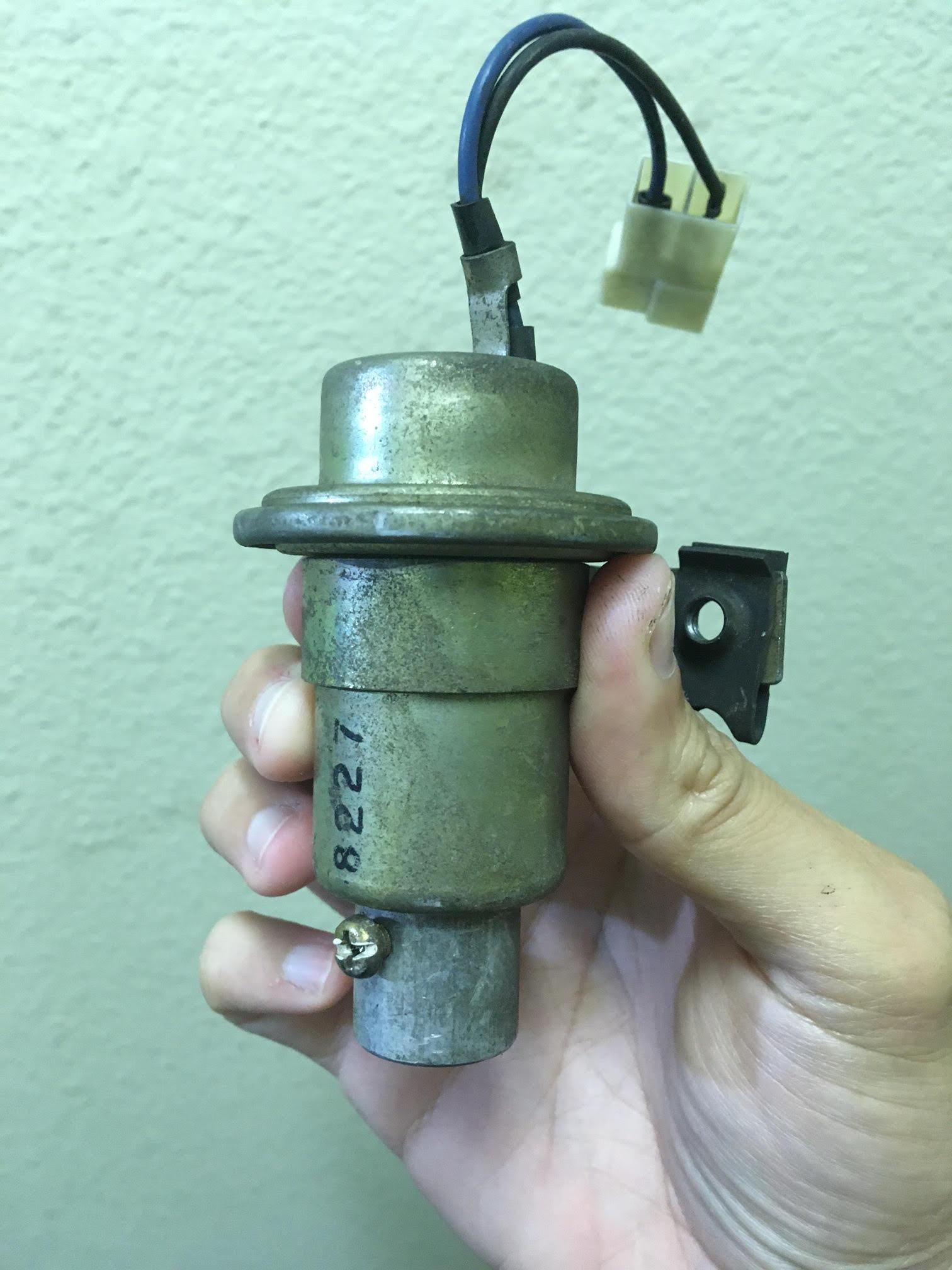
Hi guys, Having a really strange cold start valve issue here. My cold start valve is not firing when connected to the harness even though it is getting the ECU signal to do so. I connected the thermotime switch's bullet connectors together to simulate an "on" signal from the ECU which got power to both sides of the CSV's injector plug during cranking (with those connectors unplugged, the csv's plug only receives power on one side according to my test-light). However, the csv is not firing when connected to the harness (I pulled the csv out of the intake manifold and put its end into a cup to collect the gas and got nothing). I left the nozzle in the cup and used some alligator clip wires to connect both "teeth" of the csv's connector directly to the battery and it spit out gas so the valve doesn't seem broken. The csv is only about a year old and I re-did all my injector connectors so neither of those parts are vintage. Any ideas? -chase
-
-
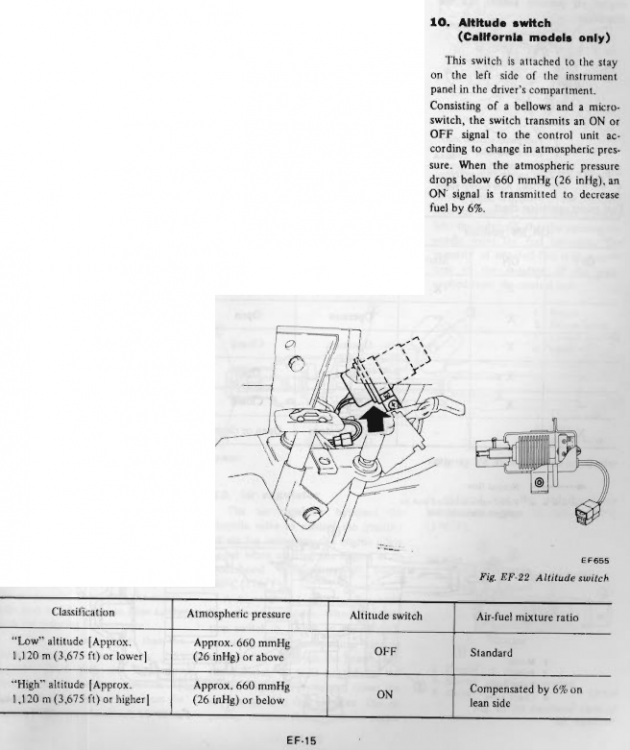
This excerpt from the FSM should explain it a little bit:
-
So with this switch on, the air filter off, and an extra vacuum leak added for good measure still wouldn't get enough air into the engine to get it up Pike's?
-
If you don't have a CA car you won't have that sensor in there but I'd imagine the connector should be. Stick your head in the driver side foot well and look up near where the hood-pull cable lies and you should see the connector that you can jump. I can see Nissan not spending the money to not include the sensor in federal cars, but creating an entirely separate loom for fed/CA cars seems like a needless cost so the connector should be there in all cars I'd guess.
-
Yes, one terminal has power and the other goes to the ecu I'm guessing. Here is a couple pics of the one I pulled out of my car:

.thumb.jpg.159212175f64ca8acdaf13b09c008672.jpg)
-
It just means unplug a vacuum line that goes directly to the intake manifold
-
I'm pretty sure your car has the connector - it just didn't come with the sensor. To my knowledge, they didn't create different wiring harnesses. If you can find the connector, use a test light to see if it's getting power with the car running and that should tell you if this trick will work for you.
-
I removed the sensor itself (and substituted a switch) because i doubt it worked and I couldn't test it with the FSM's test method since the rubber connector leaked air haha
-
Question for you guys, would jumping the terminals to engage the high-altitude switch improve my mpg? Also, would this cause any engine damage if run like this in an area that doesn't require the switch to be on? Apparently with it engaged, it decreases fuel by 6%.
-
Update for you guys. I created a bypass switch to enable high-altitude mode using a standard flip switch and two spade connectors (one plugged into each of the plug's 2 sockets). I gave it a quick test and it seems to be working (after confirming continuity). If your bypass switch is working, you will notice the following with the car warmed up and any vacuum line unplugged: Switch on: the car should have a fairly noticeable stumble Switch off: the car should have a mild stumble if at all
-
Well that's odd, I wonder why they did that
-
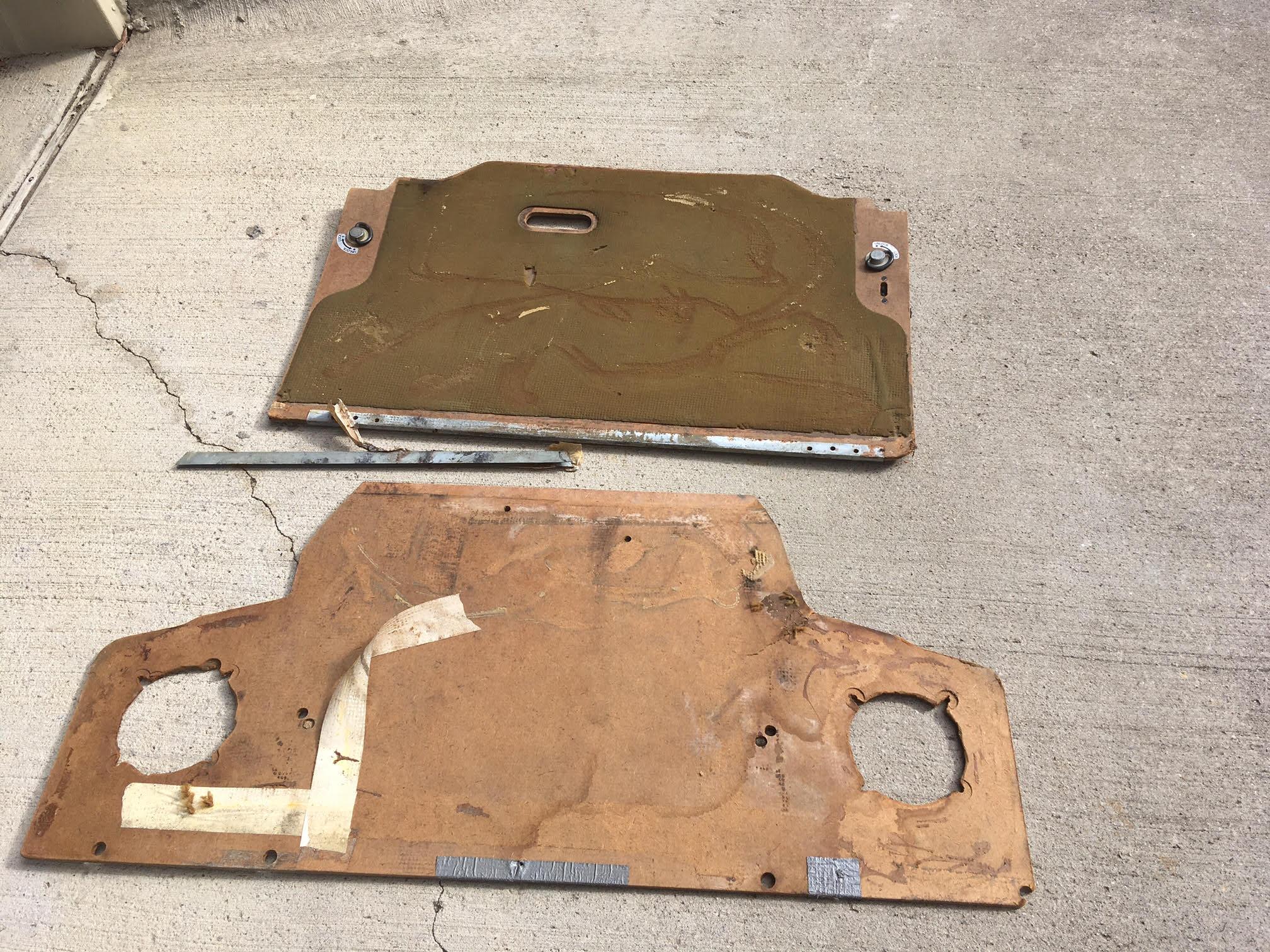
So it looks like I'm missing the metal piece that lines the aft piece of wood in which the hinge attaches itself (and of course the hinges too haha). How does that chrome piece that sits on top of the carpet mount? I'm guessing it has screws that go through the carpet but what does it fasten to?
-
Awesome, looking forward to it
-
I always thought the front piece (the one nearer to the driver) opened as well in order to grant access to the two small storage bins where the toolkits were in the 240. Am I mis-remembering?
-
These are awesome shots, this will be a massive help. Could you take a couple pics of how the front board is bolted down and what is screwed into the middle brackets?
-
Ah gotcha, so there are long black hinges that attach to the ends of each piece of wood and are screwed into the bracket? It seems that the two wooden pieces don't connect to each other then? Any idea where I could get that hardware? I've looked everywhere...
-
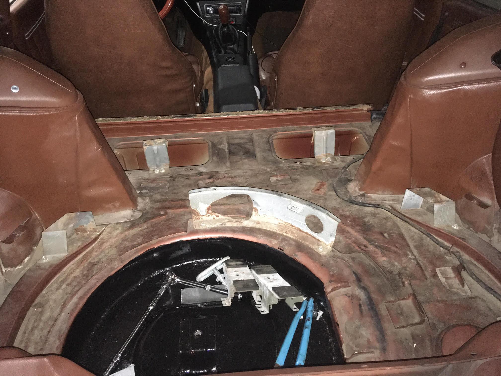
Awesome, thanks for this! Is there any special hardware I use to mount the floor? I seem to remember they have some sort of hinge so they can be raised and lowered instead of being screwed into the car, am I wrong? I do have the side wooden pieces, but didn't add them to the original picture. Here is what my hatch area looks like: So it looks like I have the brackets but am missing the mounting hardware?

-
Hi guys, Can someone tell me what hardware I'm missing and how to connect the subfloor? These have always basically rested in place in my car and were never really connected to anything. Here's what I have: Any ideas? -chase


.jpg.6e7e6b49d6d122a8a97b6f3bb450db0f.jpg)