Wally
Free Member
-
Joined
-
Last visited
Everything posted by Wally
-
I did some. A couple videos said not to use a ballast resistor with this setup. However, the car came with with the pertronix and and resistor was installed. I did take a few photos of this before disassembling everything for paint. The car did run....not that great admittedly. So that confuses me a little. Do i use the resistor or not and if not then what to do with those extra wires too.. The setup in this google search seems fairly simple but again there will be a lot of leftover wiring....maybe that is normal though. I may need to outsource this part of the re-build
-
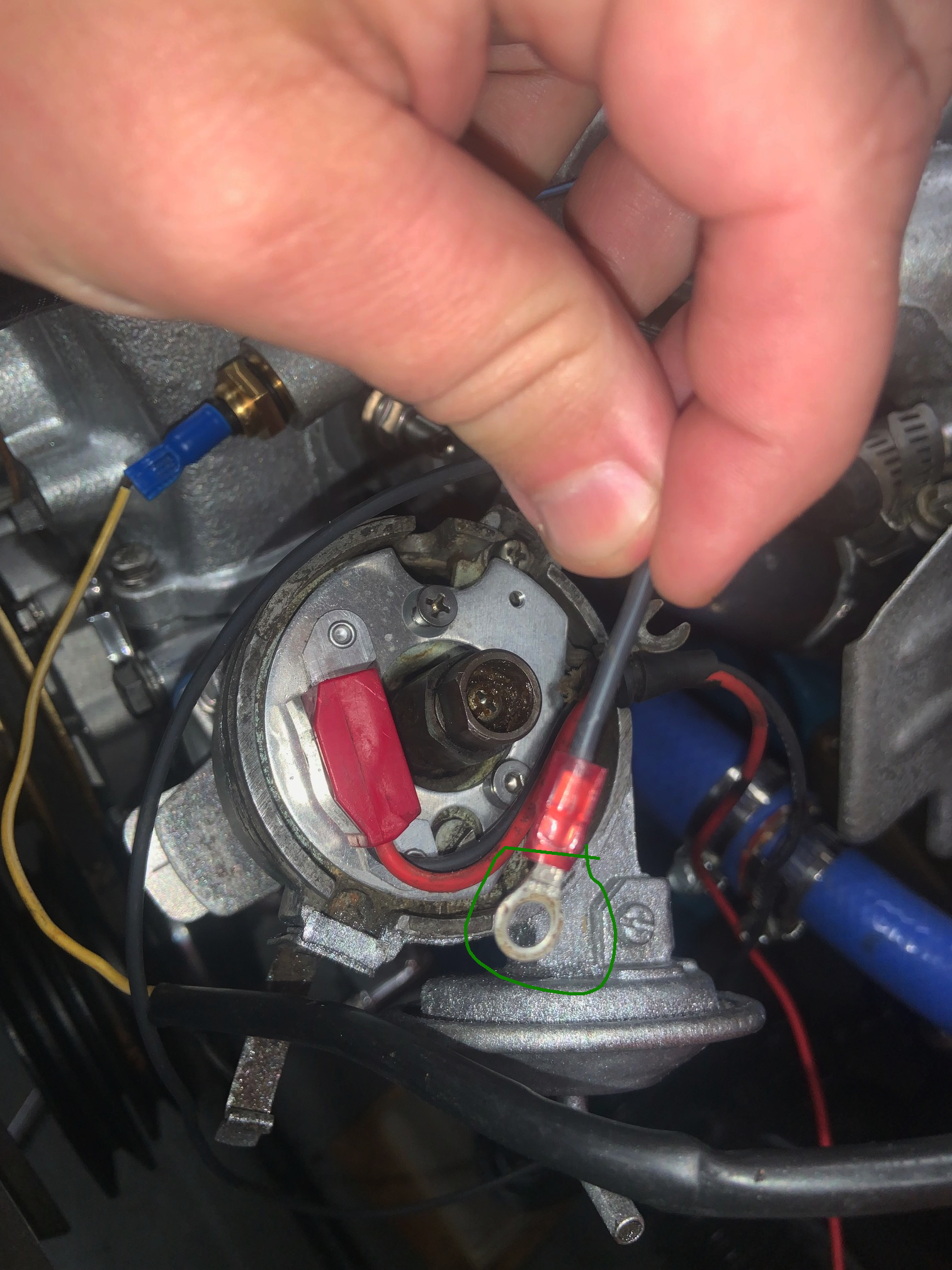
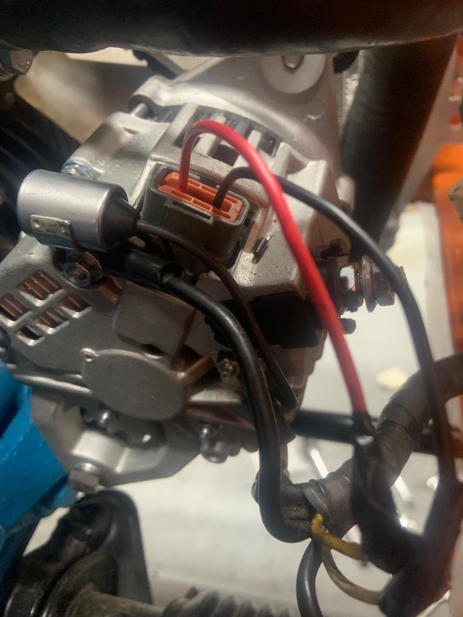
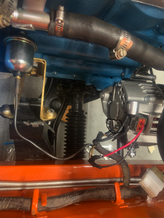
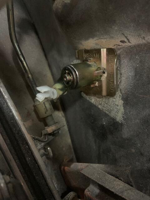
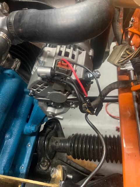
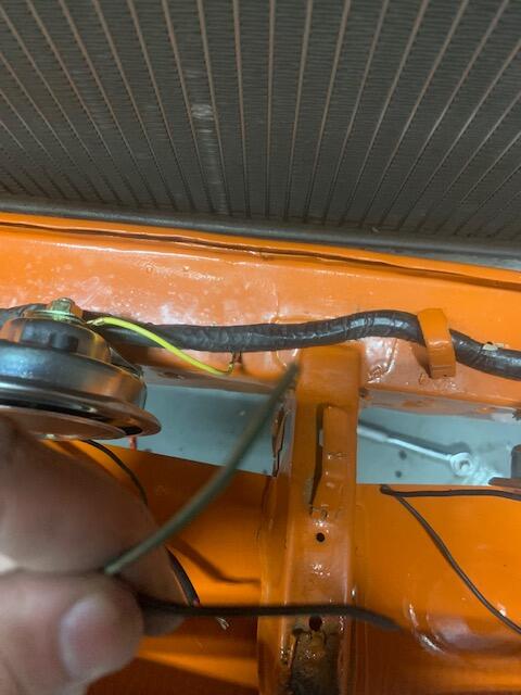
thanks all. that was a big help. 2 more questions on this ignition if i may. I think i have the ignitor II setup as well. I have the red wire hooked up on the coil right, but the black wire i circled in image 2797...does it ground to the chassis? I am thinking thats where it was originally Last in image 2798. I know i have one end of wire hooked up properly on the ballast resistor mount (at least thats the way it was when i bought the car originally). I can find where i put the other end though?


-
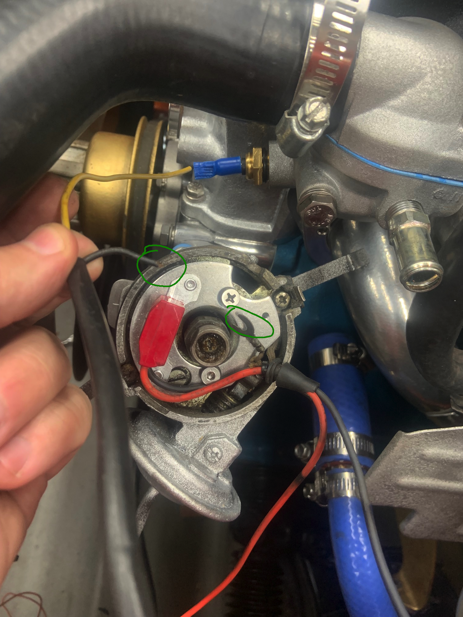
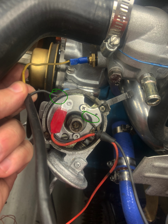
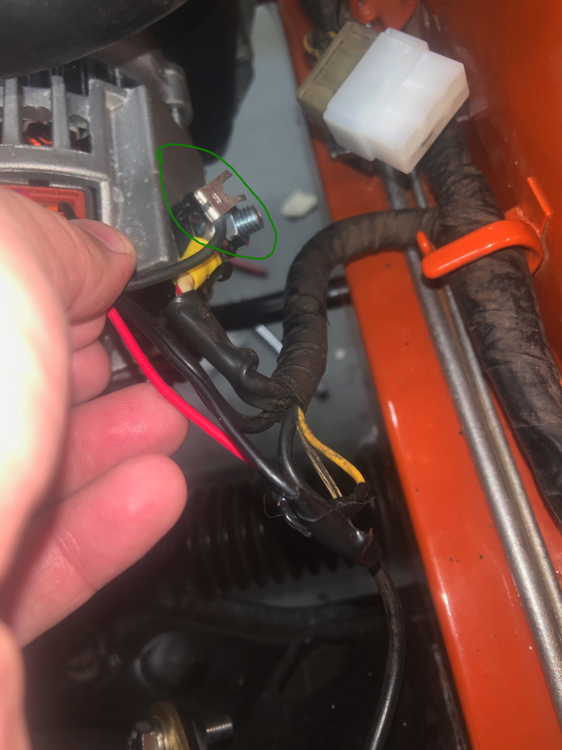
I have a few ignition questions please. Here are the first 2. 1. the black wire (with yellow wire). Any idea what it is or where it goes. It was broke off when i bought the car. 2. the other green circle beside the the red wire has a fork that goes somewhere. Should it just go under one of the screws? thanks much
-
Roger that. will an upgraded alternator cause an issue with the ammeter. I believe the gauge goes up to 45 and the new alternator ideally puts out 70+
-
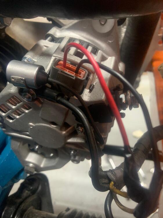
There are no letters on back of my alternator (at least i dont see any) Before i cut the wire to add a new larger diameter connector for the B terminal let me make sure i understand. 1) image 2793, its the "ground" and has 2 wires connected to it, one of which is the condensor body? 2) image 2795 is the wire coming of the condensor (with the fork) it goes to this "B terminal" for total of 2 wires there? 3) This wrong hookup....its likely its what burned up the fusible link on starter? Steve, dont worry, i can 100% guarantee i will make another bonehead move...probably soon too.
-
thanks! i assume this was the issue then. i moved that wire to B terminal like said. The item in at top, condensor?, it has a wire with fork on other end. I have left it where it was original with other wire in black circle. Will that be an issue?
-
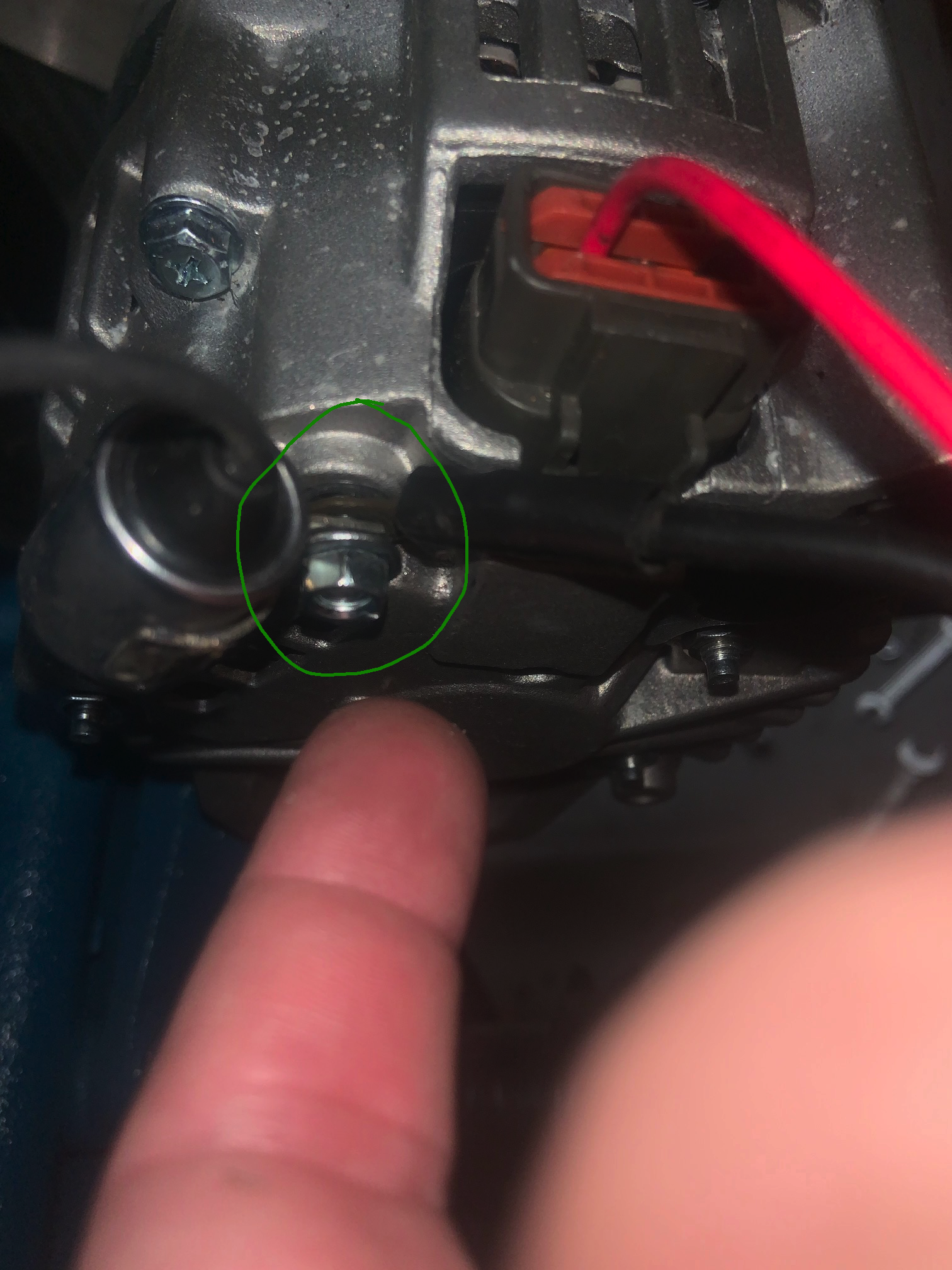
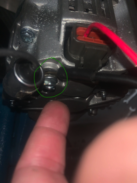
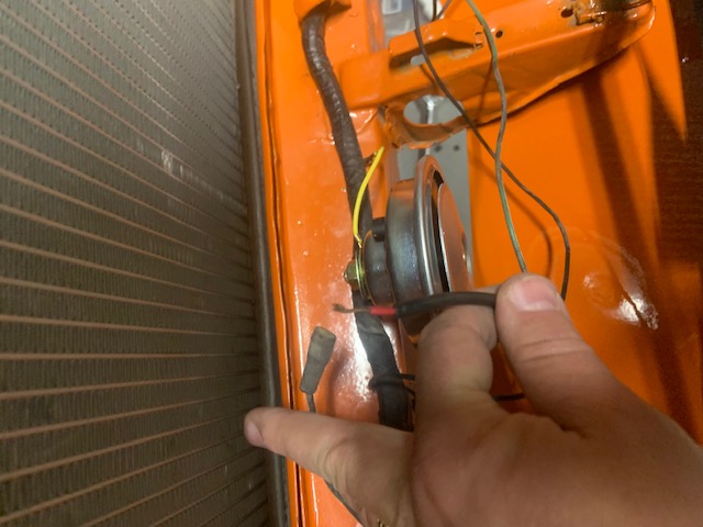
I dont. I can take an image of the alternator though. Not sure if it helps? One of the nuts toward the bottom was loose. i drew a circle in black around it. Maybe this is the culprit. New alternator with the new connector type and i did use the voltage reg blockoff

-
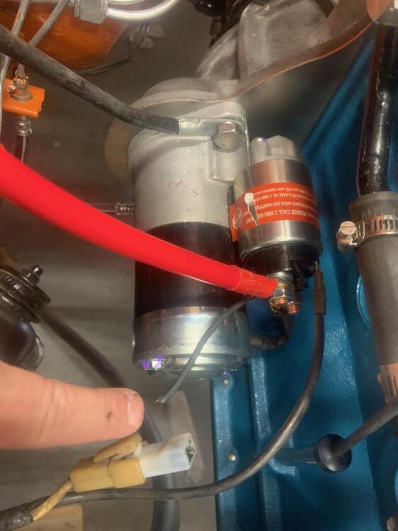
Shorted and burned the wire soon as i hooked it up. You can see where it burned out. Can anyone see how i hooked it up wrong? I have the black fusible link right behind the red battery terminal wire. Was i supposed to put it on the other post/nut right next to that one?
-
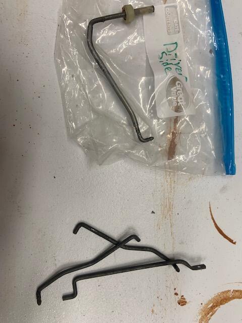
How would you suggest bending them? Any special method or just brute force? I would buy a pair of OEM if i could find them but cant. Car didnt come with any on it when i purchased so cant do any refurb.
-
yes. those are brand new pieces
-
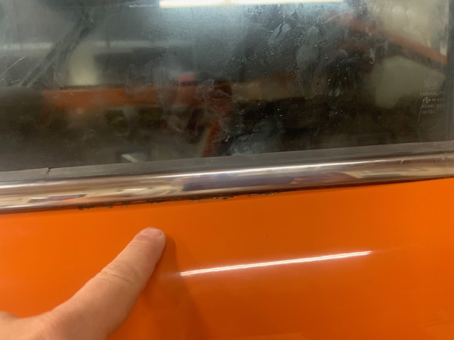
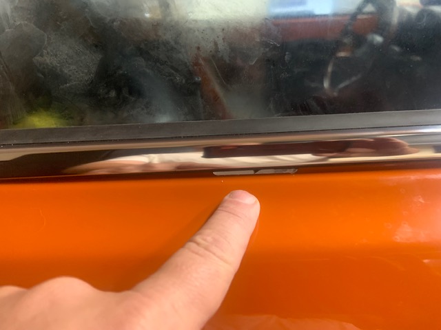
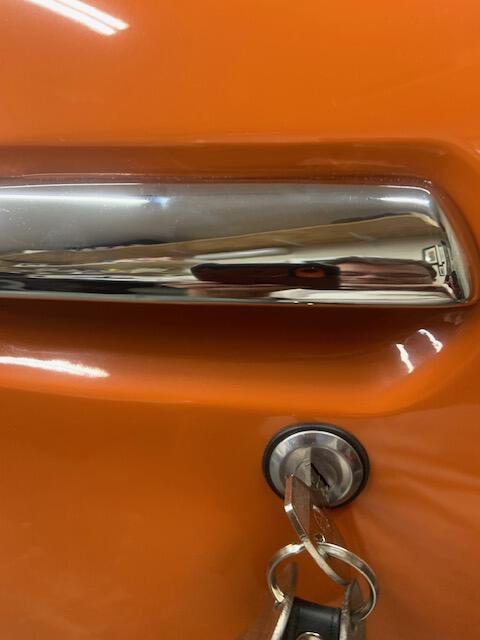
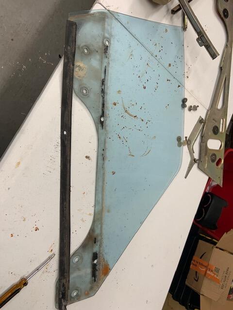
On the driver side i put some strong adhesive to try and get it to stay down to where it should be. It wont. it pops back up and you can see the line of black adhesive which makes it unattractive. On the passenger side i have not put any adhesive (for comparison). You can see its not going all the way down and can see the silver window roller ball. Thoughts on what to do?
-
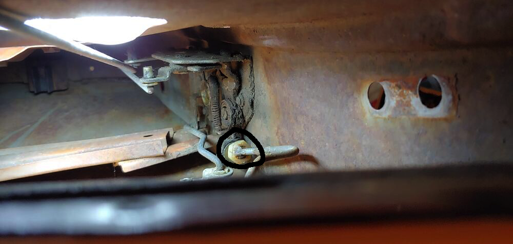
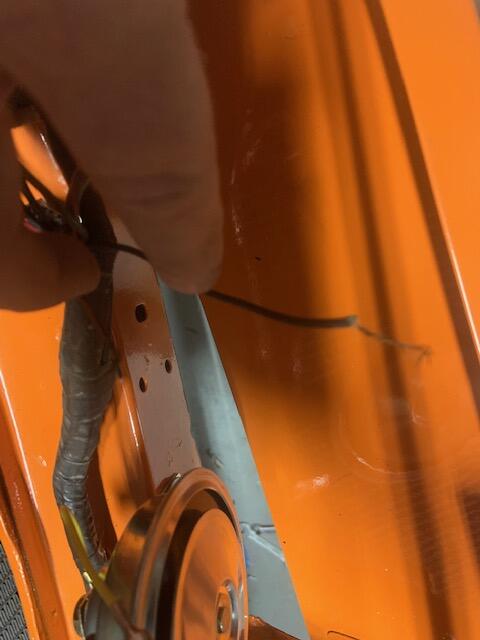
went ahead and took window chrome off to get better look. I took all locking stuff out and played with it to understand how it all works. I have passenger side all working. Driver side is 90%. Issue i saw causing all the issues was piece i circled. It will prevent something from operating if its up to high or too low. Getting it adjusted right is crucial...imo On driver side only thing not working as of now is using key to lock from outside. I am thinking its the door lock itself and needs a little adjustment. Between installing new window regulators, bushings etc. and the door locks think i may have to take a break.
-
Not sure. i know my 71 is a series 2 if that matters. Also, those locks and mechanism are not orginal to the car. I bought news ones from either zstore or ZCD. Not sure if that makes a difference. i did put rod in though and it aligns fine with clip in place
-
Awesome guys. thanks. will review images and Figs. I already see where one things goes from them. Just the lock knob now to work on.... Should the outside lock only move to the left and right 45 degrees each way?
-
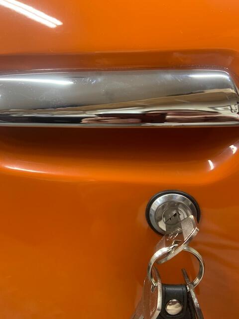
Need some advice on door locking mechanism. I have the interiors side of door handles operating fine. I also have the outside chrome handles in and working. What i cant seem to understand is 1. how i get the outside door lock attached.I have an image with the really white clip for the outside door lock. does one of the rods slide into this and the opposite side of the door handle? FOr some reason thats what i am thinking but if so not sure the right rod. 2. The inside door lock, stopper whatever its called is frozen. I know it works as it once was, its just not hooked up right. anyone have any reference material, images, info. I have rods not currently used in image. one on ziploc i know goes on driver side somewhere. thanks guys BTW, Not sure if this is in the right place.
-
cant seem to find anyone else selling this? does anyone know another place? Zstore is out of stock and no clue when or if they will get any more.
-
wait a minute. so that adapter plugs off the voltage connector and thus eliminates it? is that right?
-
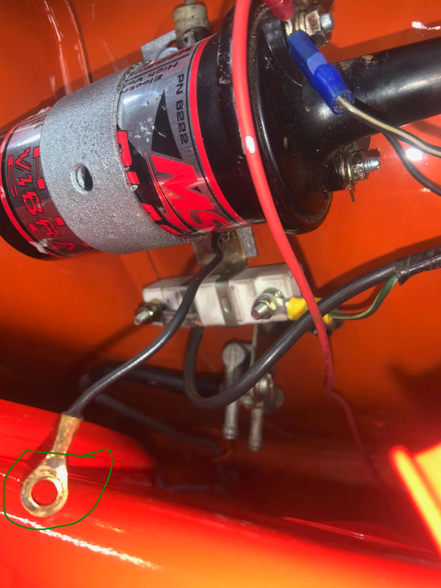
Thanks all. The voltage connector is connected with no problem. already had the connectors for it ready. I just looked with a flashlight and that side lug has a B, for battery i am guessing which mean i move the white&red wire over there. The original connector is too small for that bolt so will need to put bigger connector on. shouldnt be an issue i wouldnt think. Didnt see any other letters like E (ground) just gonna use the one i have it hooked up to in image. I have bought a lot from different places. ZCD has NO PHONE and is slow if they respond to email at all however their website is up to date on inventory. Motorsports will pick the phone up and help you really well....its just their website stinks. Last week i had about 1400 in an order with them (all listed in stock) after waiting and then calling them only 2 items ($40 bucks worth) were really in stock.
-
OK. here is a link to alternator. https://zcardepot.com/products/alternator-high-amp-80-240z-260z-280z?_pos=1&_sid=5cde58cef&_ss=r&variant=19280584015985

-
got the fusible link and and installed. Few more wiring questions 1) In image one, can someone confirm my hookups on alternator. These are the way it was on old one when i removed. However, new alternator has bolts on side for something but i dont see anything to connect. Is it just an extra i dont need? 2) My new horn hookups. I have two spade connector on bottom of each horn and one yellow wire coming from each horn. So i am assuming 3 wires go to each. Not sure what wire goes where though. Tried to take some images to show wires i have. In the middle image is a green and black wire that are long enough to go to either horn. In driver image one wire appears to be green and other black. any help on the horns is appreciated

-
thanks. found a replacement on ebay...just needs holes punched https://www.ebay.com/itm/224553119269
-
working on the windows. taking everything out. cleaning. replacing regulators etc. I got the rubber piece off the driver window pretty much intact. Would like to replace but havent found it. Anyone know where you can buy them or what this is actually called?
-
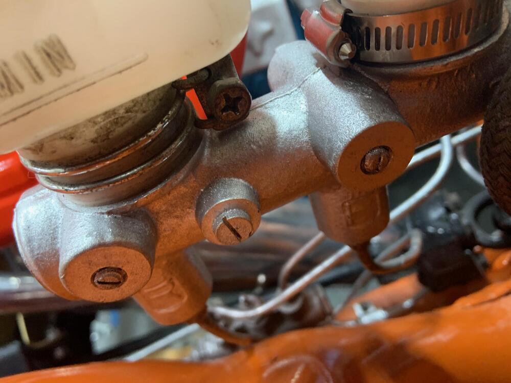
dang. you just burst my bubble. Yeah.... i put some fluid in the resevoirs and turned that bleed valve on the brake MC and nothing came out. I am thinking it should? i understand why and how to bleed and the brake lines but I am not sure why you bleed the valve from the MC?
-
threads were same. just moved things around... there was a tiny round ball that goes in first on side you are sealing off, then put set screw in and tighten. Finally something is an easy fix
-
I be danged! So i am looking closer at my M.C. that came with the car. Image is on other side near fender wall. Looks like you can switch screws and bleed valves to opposite sides? Doesnt it? this would 100% fix my issue. Looking at images of other MC my doesnt look right. The fluid holding compartment, the rear is usually a straight tube. If i cant switch valves around i will buy a new MC and see.