BAS_DXB
Free Member
-
Joined
-
Last visited
Everything posted by BAS_DXB
-
Fixed ✌️
-
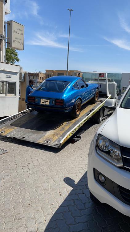
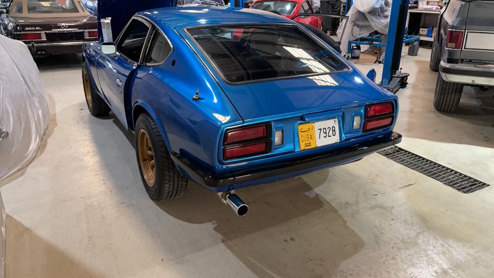
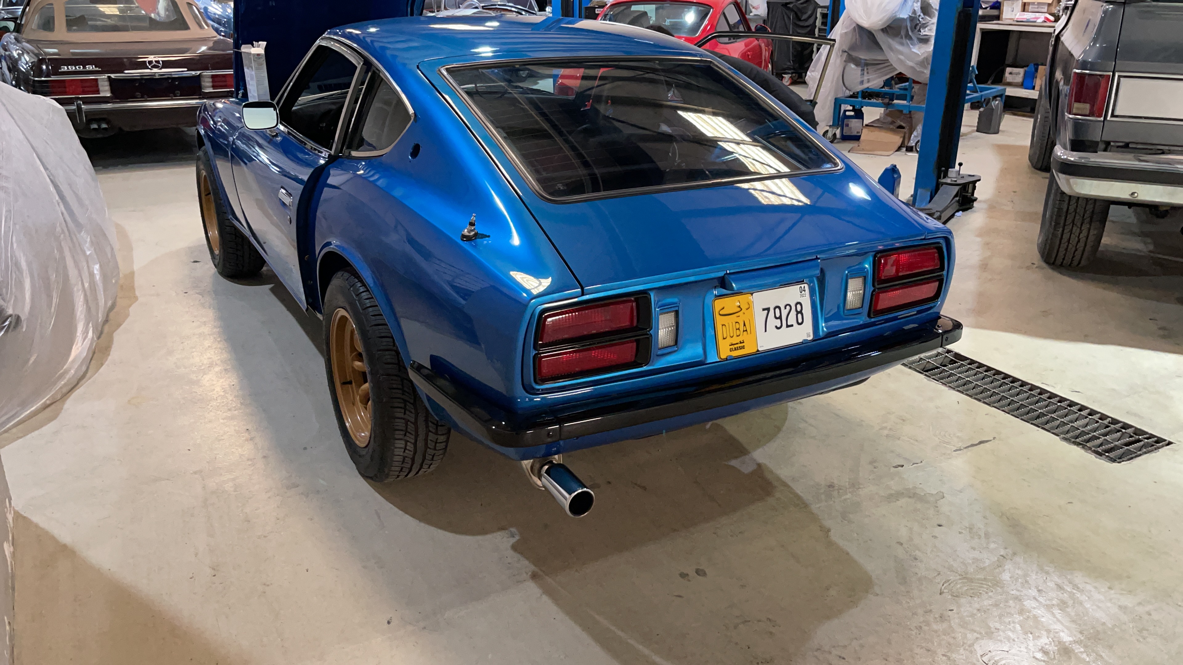
Another win yesterday 🙏 Passed the test and registration as a classic, first time the car got license plates since it arrived in Dubai on 17th of September 2020. The Road and Transport Authority is literally 1km away from the workshop, but risking 6 months confiscation of the car to drive without registration was not worth saving 20$ for the recovery truck... The way back was the first drive, EVER, and was FANTASTIC ! Now I can focus on the mapping and test driving, still waiting a bit for the paint to fully cure before the polishing (that's why the Z side emblems are not on the car yet). I will probably lower it a bit more, especially the front, and still have plenty of work to clean up the engine bay, once I wired the fan control and changed injectors and CAS connectors as well. Recorded the start up and rev after driving it back from the registration: https://youtu.be/9yHdlEbfSG8, there is lot of work to be done.
-
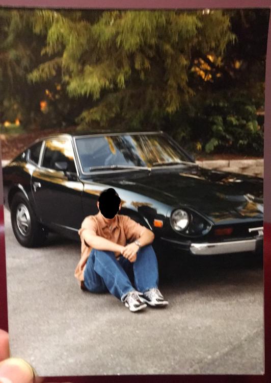
This is a picture sent to me by one of the PO (1998-2006), taken in Nebraska between 1999 and 2000, after the first repaint from Pacific Blue to this pitch dark green, this is his nephew graduation picture.
-
@wheee! always got great findings, and I ordered the same Tachy converter from Gene, UAE was not in his destination list for shipping but he agreed to give it a shot, so let's cross fingers so it doesn't get confiscated as it apparently happened in the past. I am also ordering the mechanical to Electrical VSS converter (metric) from Protuners, as I already converted my speedo dial to kmh + electric pump for 60psi as my FPR is set at 3.0bar and my fuel pump seems to be a little weak (needle bouncing 42-50 psi on the gauge). Already received my wire loom and expecting the fuel lines today.
-
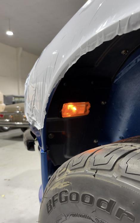
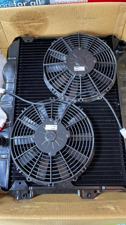
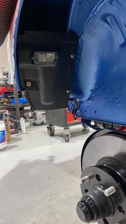
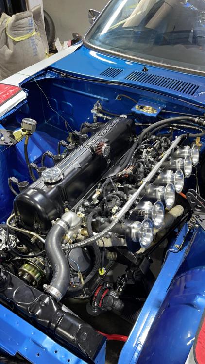
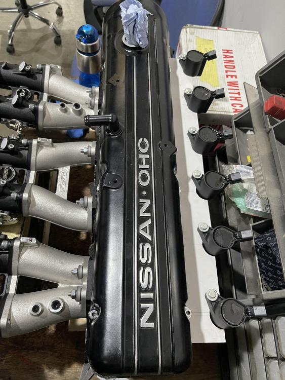
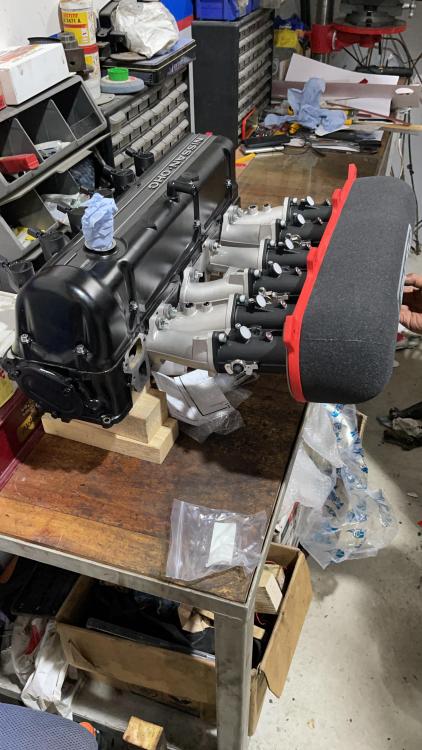
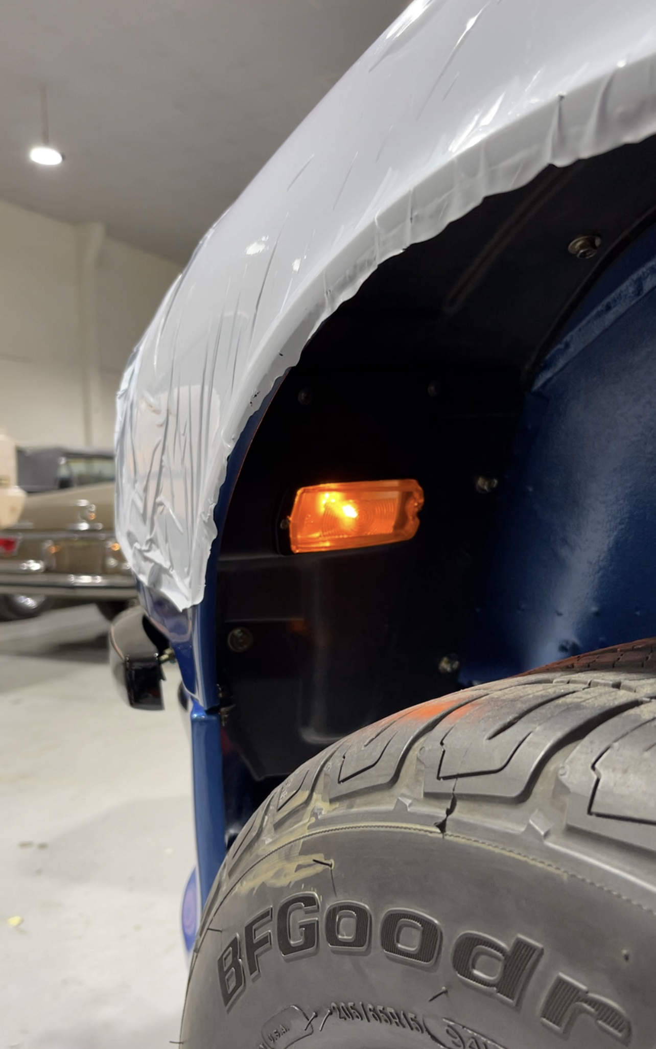
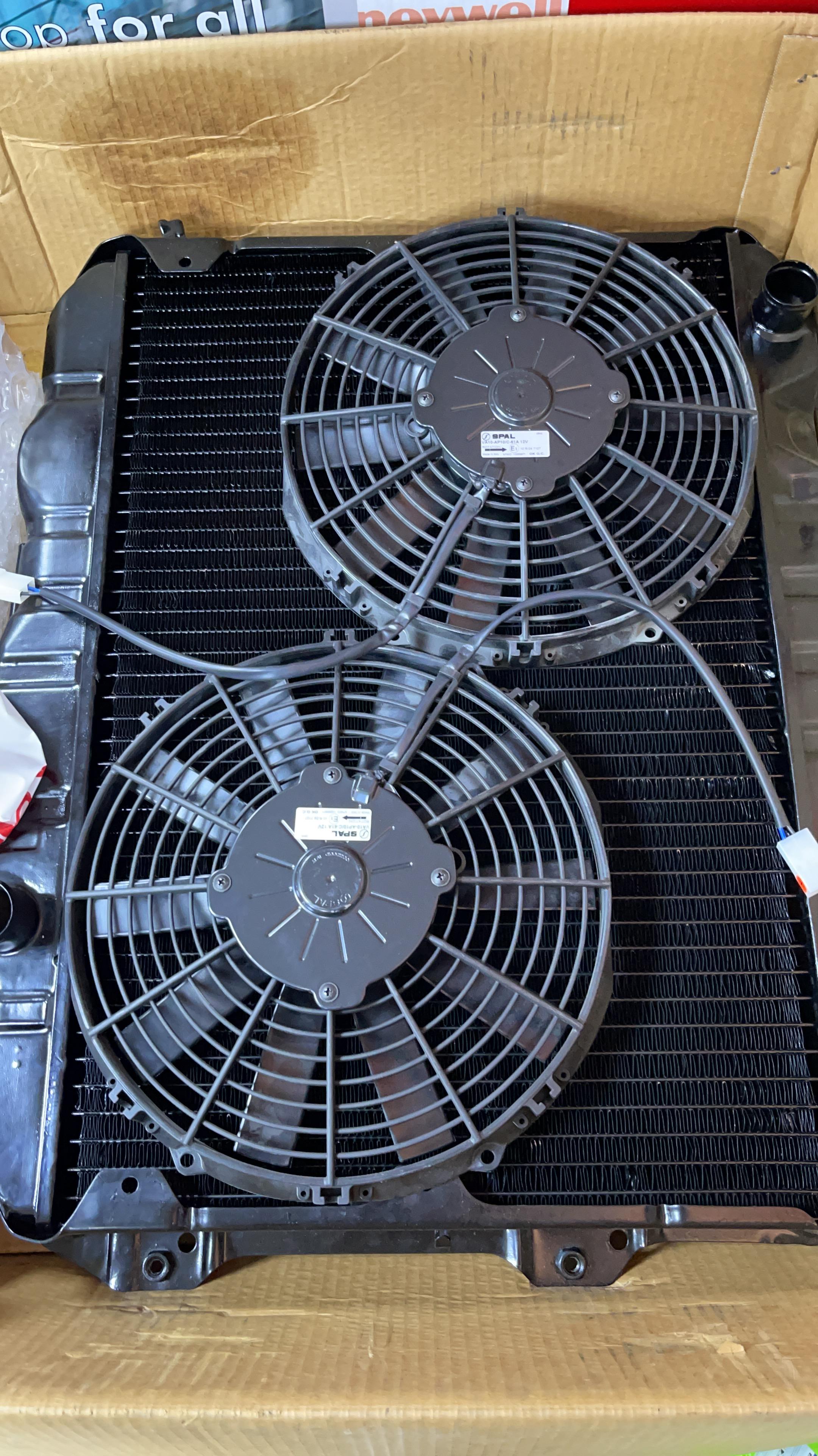
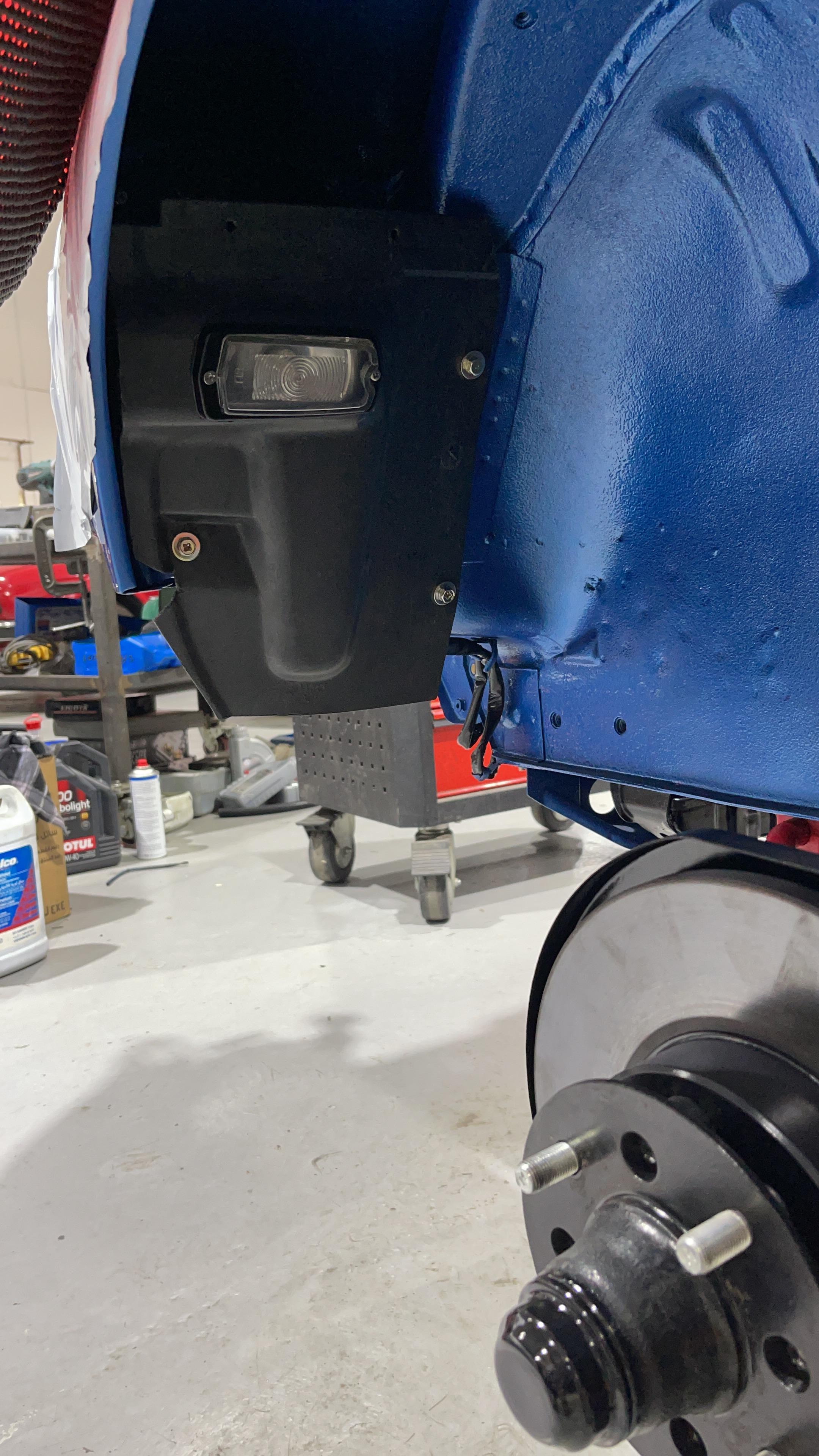
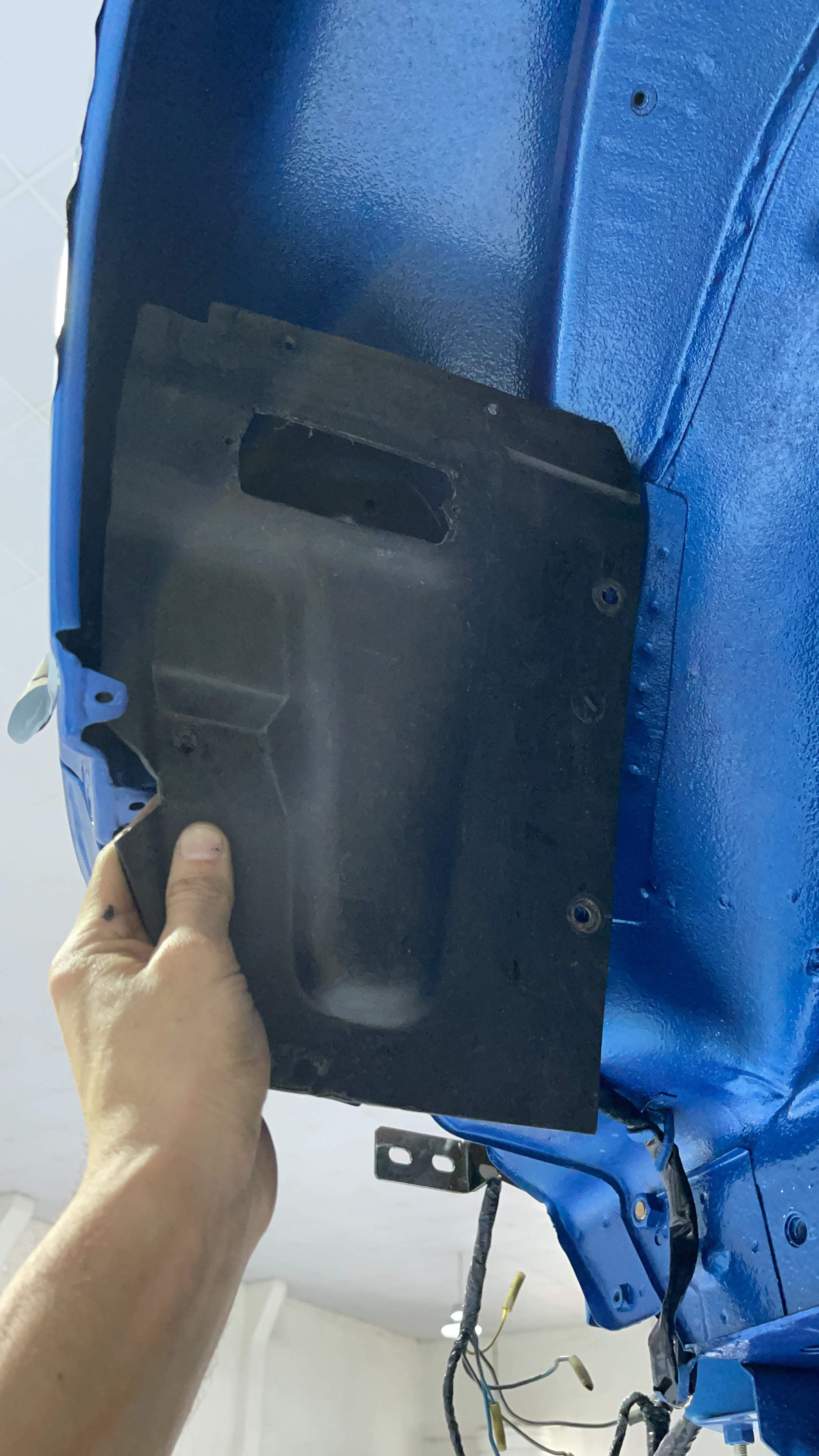
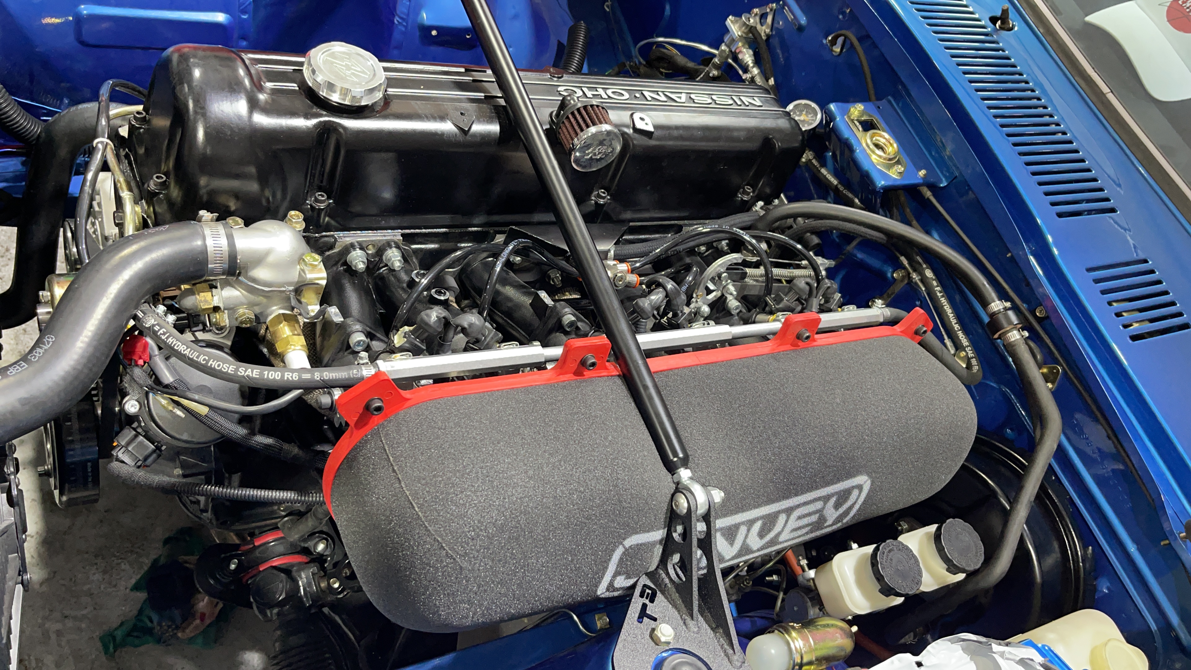
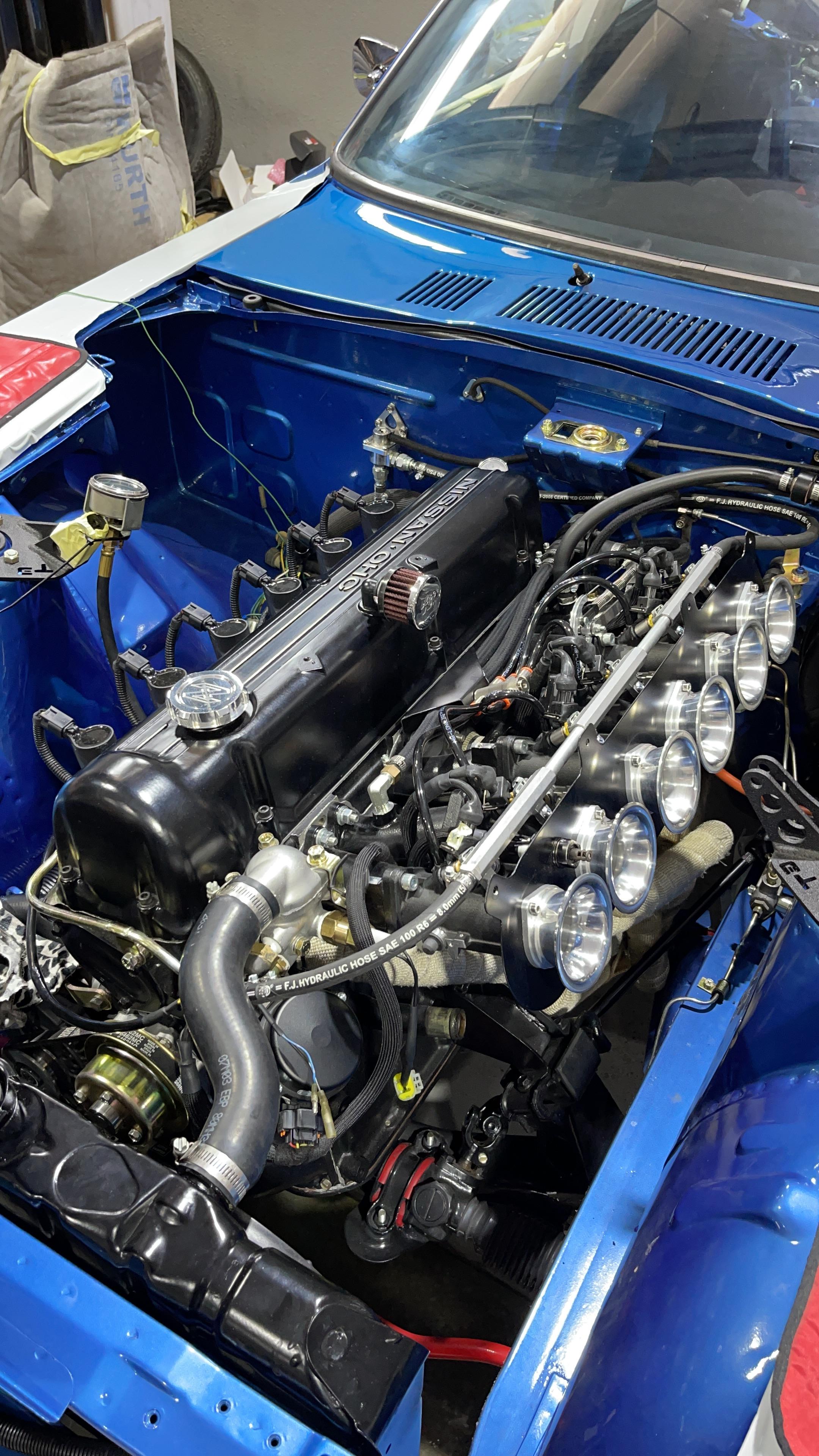
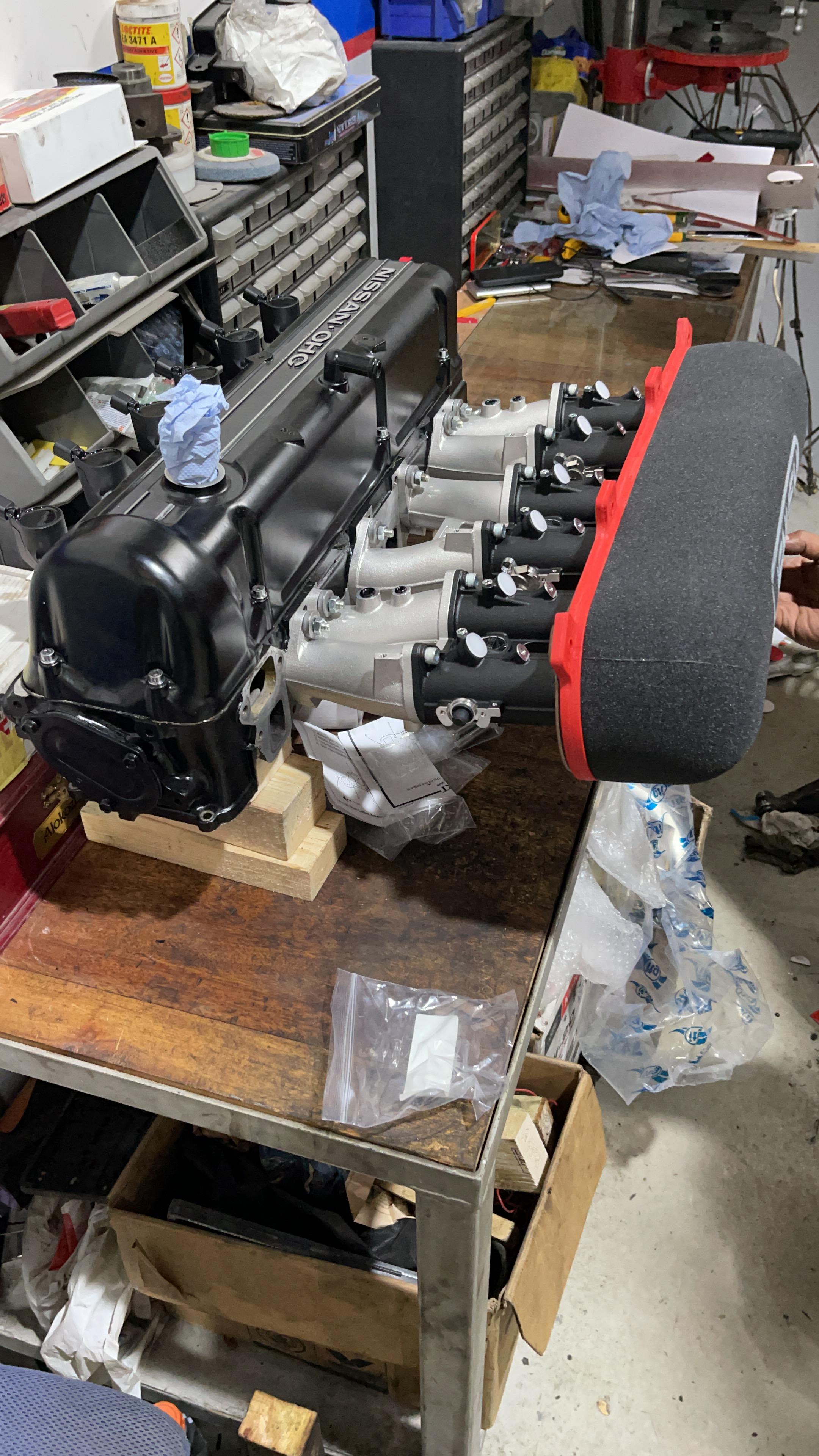
My FPR is at 3 bar, straight from Jenvey to match the injectors and the ITBs, Also noticed that my fuel pressure gauge needle is shaking a lot between 42-50psi, seems like am good for a new fuel pump soon 😂 I got a pretty decent idle today (850-900rpm), and reving sounds healthy. The idle AFR is around 15-15.2 and lowering (so richer) with higher rev, as I did not work on my AFR table yet. Had the wiring double checked for lights/signals/gauges and turned out my "Brand New" alternator from ZcarDepot is fu**, the internal regulator is defective so it doesn't charge my battery... Nice 150$ spent, sending it back to them for replacement would cost me too much time and money... Quite pissed as I will have to get a new one tomorrow morning so I can go register the car, as I now need to drive it to refine the tuning... And for those of you who remember the idea of putting the side markers in the wheel wells, I confirm it's clean and almost made for it (its tight on the back side, between the headlight and side signal bottoms, so make sure you place them as much as possible on the outer side of the car). Also, as I changed the harmonic damper to an ATI one, surprise surprise the original mechanical fan could not fit anymore... Only Spal was fitting in depth and available locally, and made a great deal on these 2, now wired to the MS3. The wiring and fuel line are not cleaned up and definitive as I am still expecting some looms, braided hose and AN fittings. I will also remove the useless temperature sensors and thermo-contact used prior the ECU control of the fans. As much as I love the air horns on the ITBs, too much sand in the area, cannot risk the engine, so big monster filter for runner, and naked for showing...


-
Thank you for the advice 🙏 Scenario 1 running less spark advance and sounds better as well. I'll dig in the AFR today: - reducing a little fuel and see how is behave and/or - adding a little air with the throttle setting at idle
-
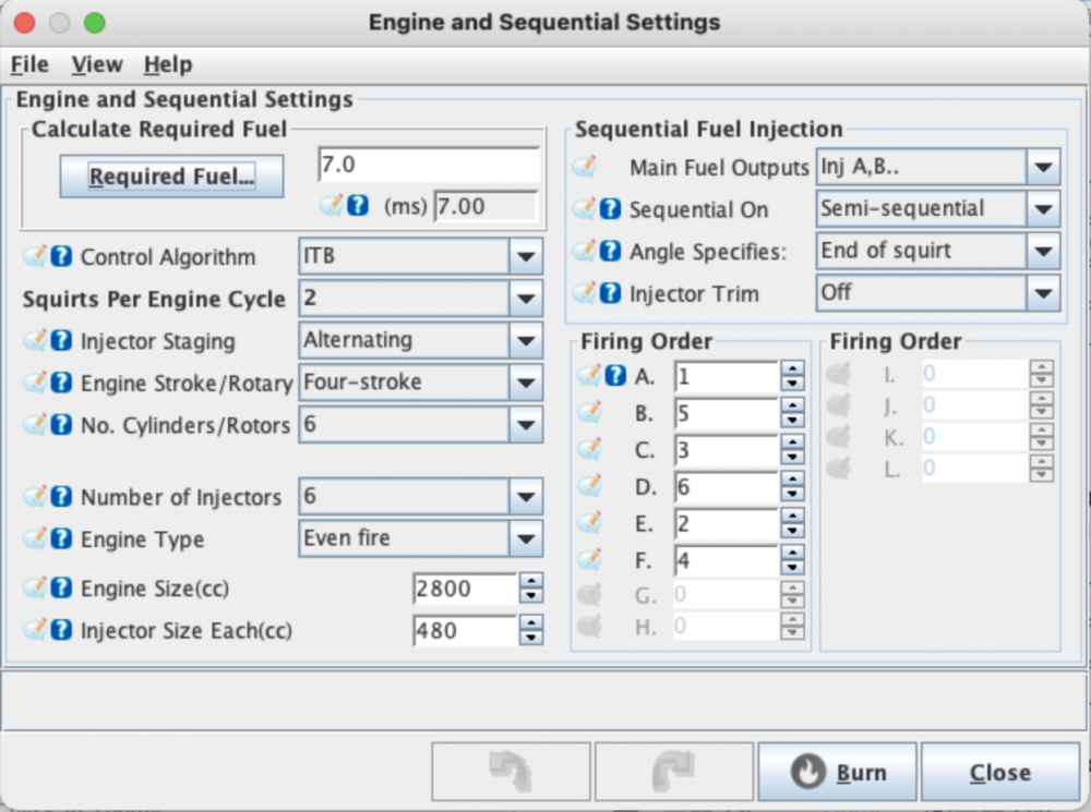
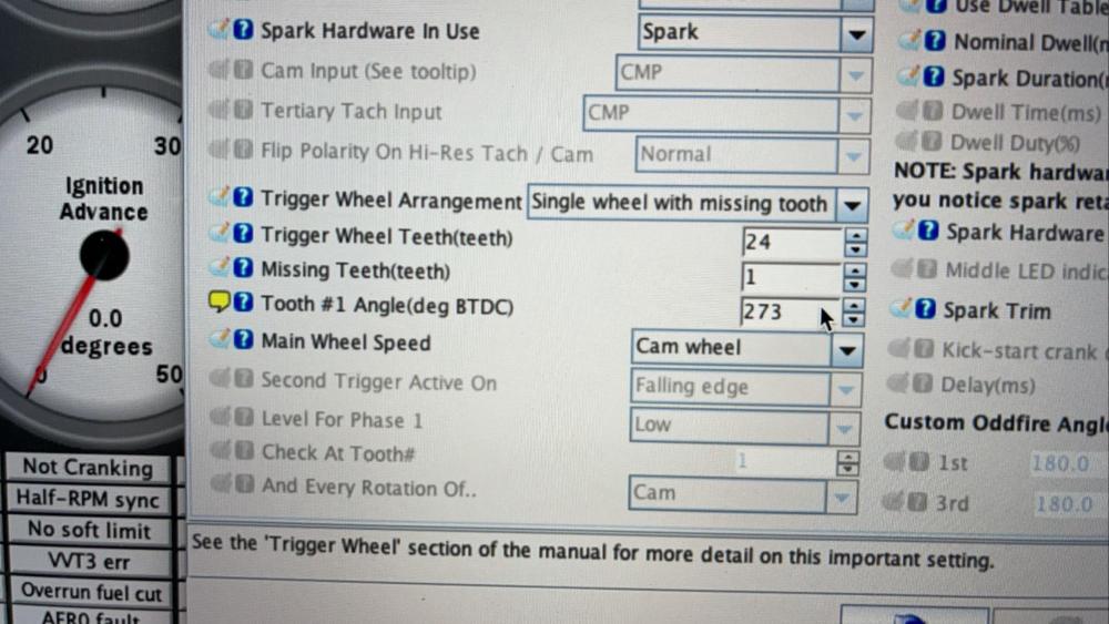
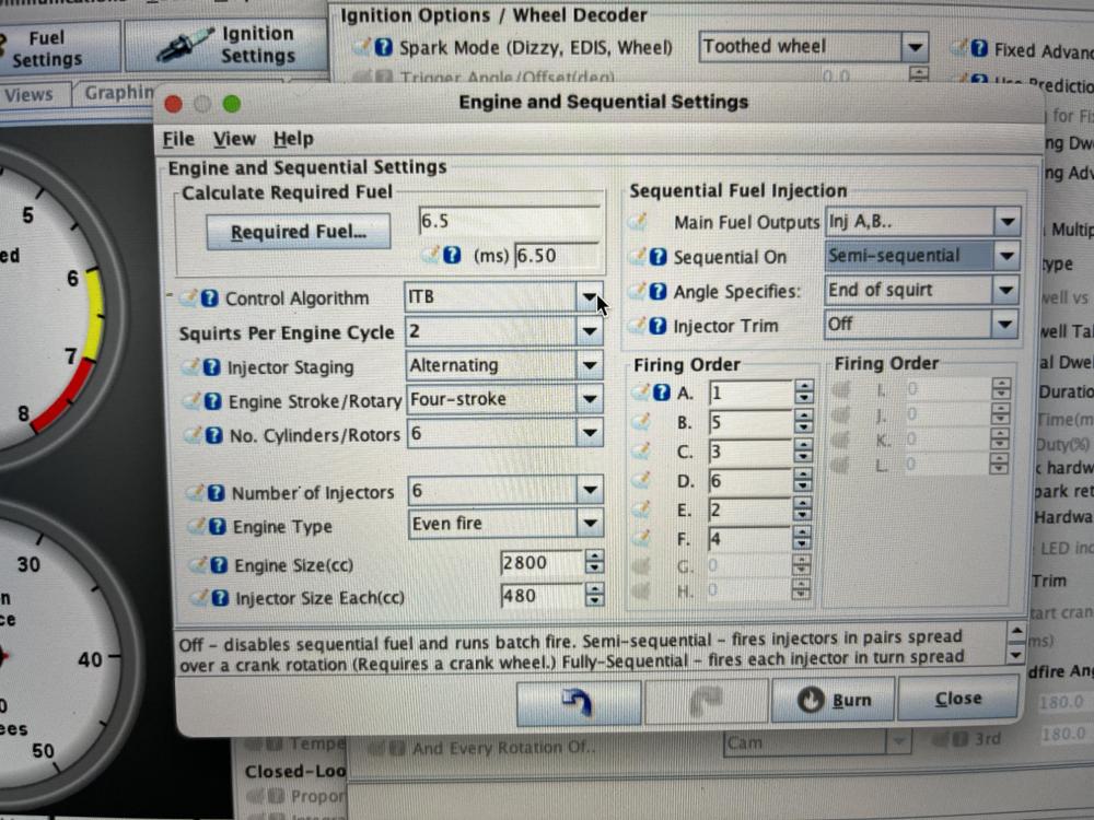
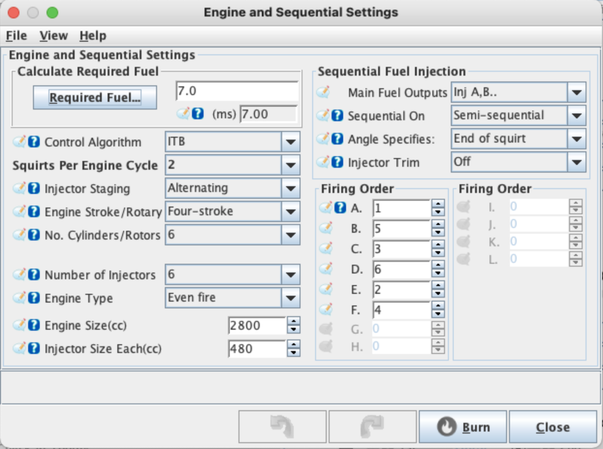
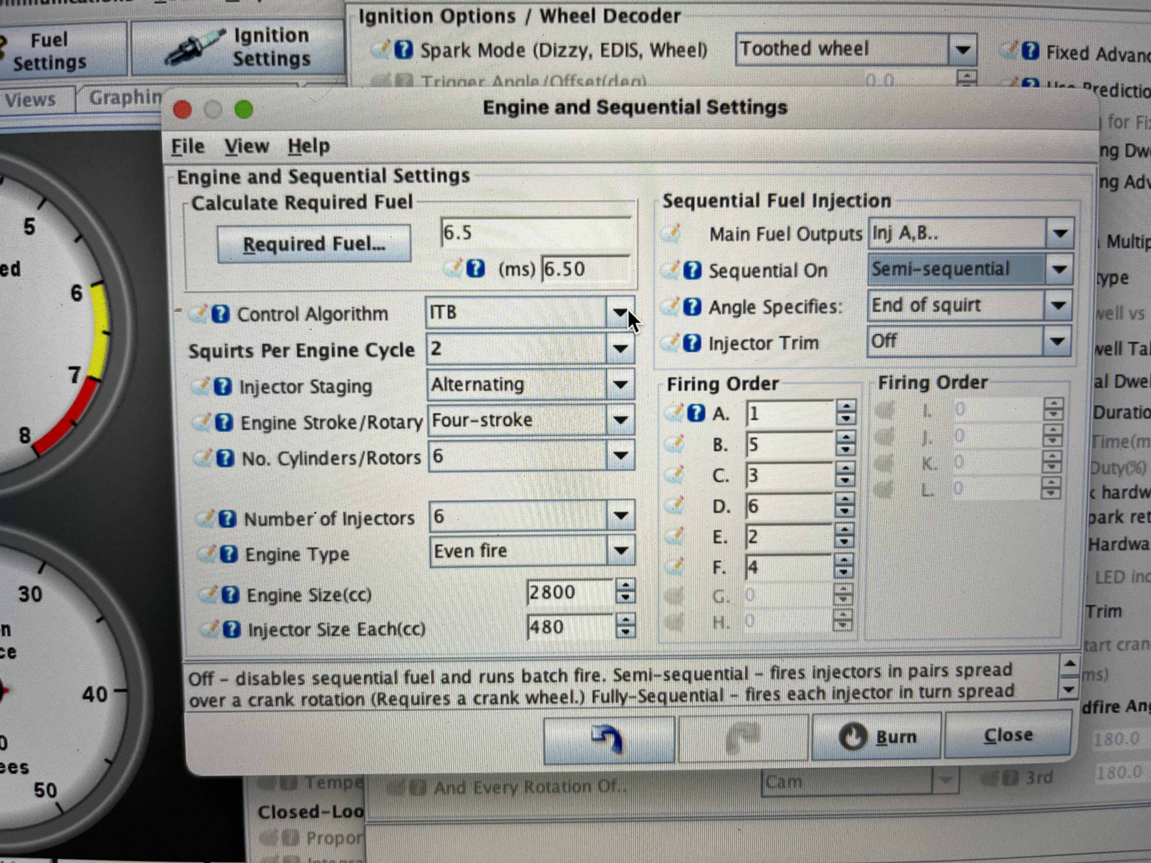
Question for idle refining following the MS3 manual: Both case I run 2 squirt alternating, primary fuel and ignition load based on ITB (not alpha N or speed density), semi-sequential, and wasted COP. Case 1: #1 tooth angle (BTDC) is set a 330* Fixed timing advance is set at 15* (same as cranking advance) Required fuel set at 6.4ms (refined the calculation with 2753cc instead of 2800cc) with my big A$$ 480cc injectors and the ITB throttles are slightly open (IAC valve taking care of the rest). Engine runs fine and stable, BUT at high rpm for idle (1200-1250) and I am 20* off my TDC mark on the harmonic damper. When going up the rpm the timing marker on damper stays same and the throttle is responsive. Case 2: #1 tooth angle (BTDC) is set a 310* Fixed timing advance is set at 15* (same as cranking advance) Required fuel set at 6.4ms (refined the calculation with 2753cc instead of 2800cc) with my big A$$ 480cc injectors and the ITB throttles are slightly open (IAC valve taking care of the rest). Engine shaking a little, acceptable idle rpm (800-900) and I am on my TDC mark on the harmonic damper. When going up the rpm the timing marker on damper stays same but the throttle is less responsive. I know this is idle and the fixed advance is not meant to be for all rpm range, so it would eventually arrange the RPM and engine shaking once using the table (that I will have to make anyway). From your experience, better to start from case 1 or 2 ? Also in both cased I run rich and the gasoline smell is everywhere, AFR gauge shows 10.2 (I have a Nissan 350z narrow band O2 sensor), but I respect the required fuel calculated and the air coming in the engine seems minimum => Will try to reduce injectors to 1 squirt and refine the timing to ensure the whole mix is burnt.
-
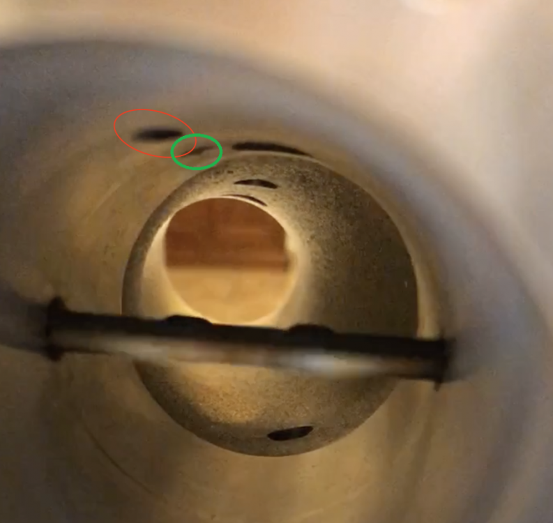
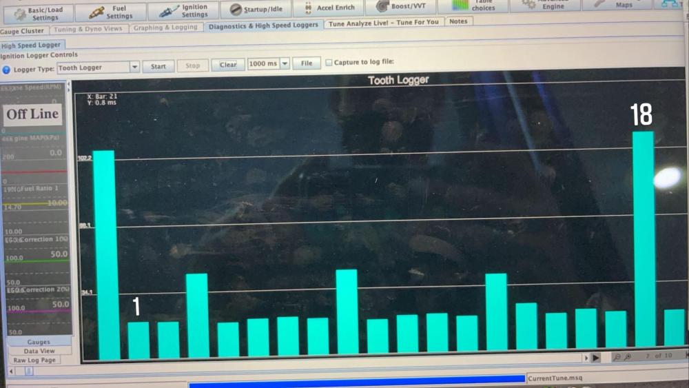
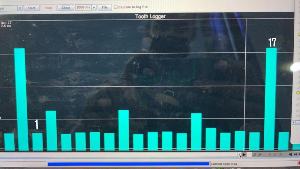
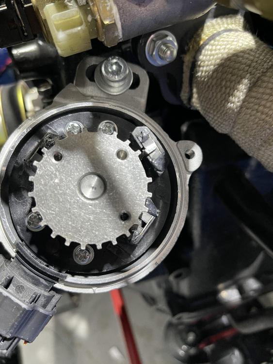
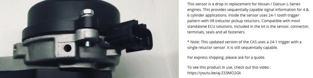
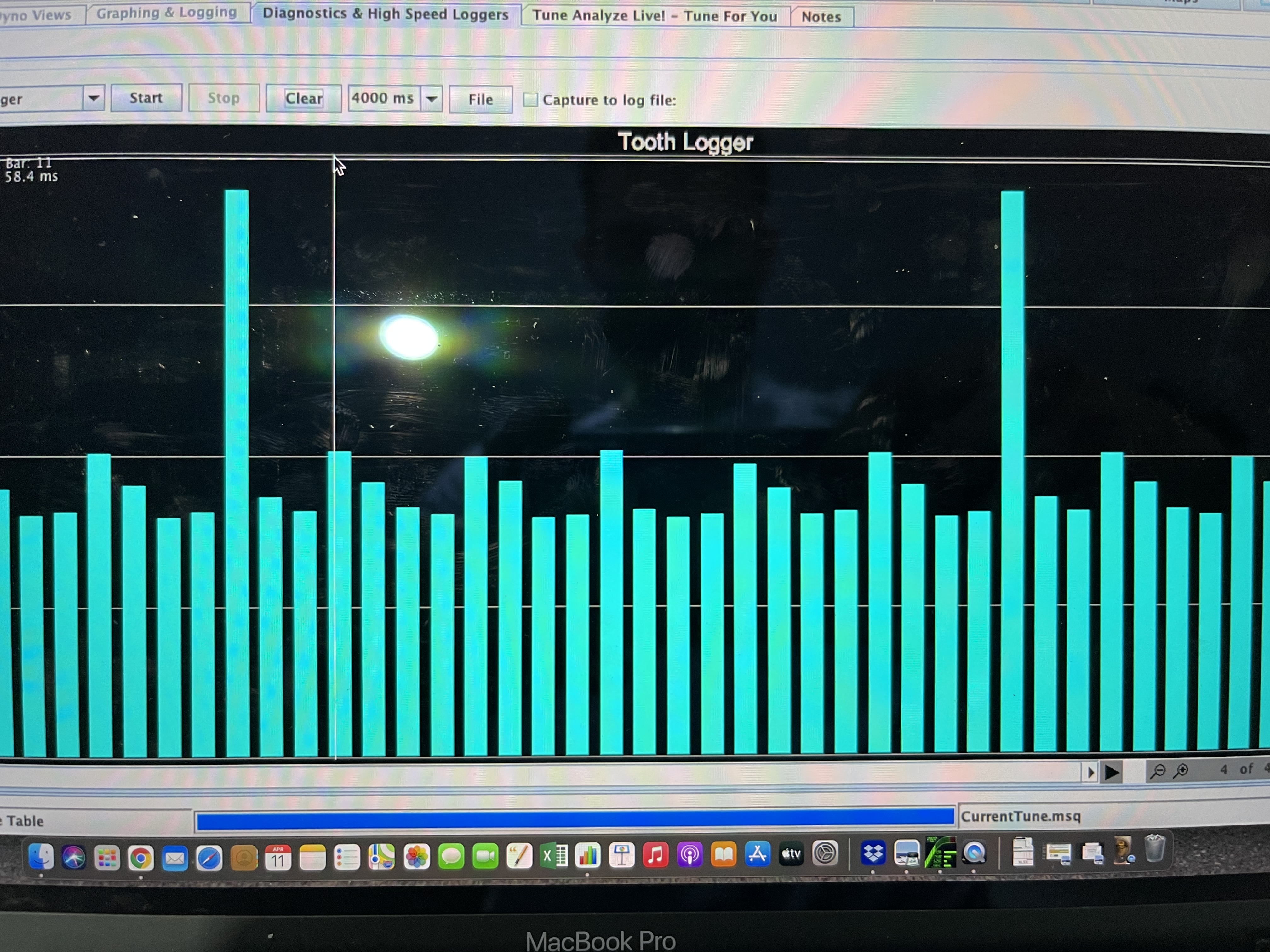
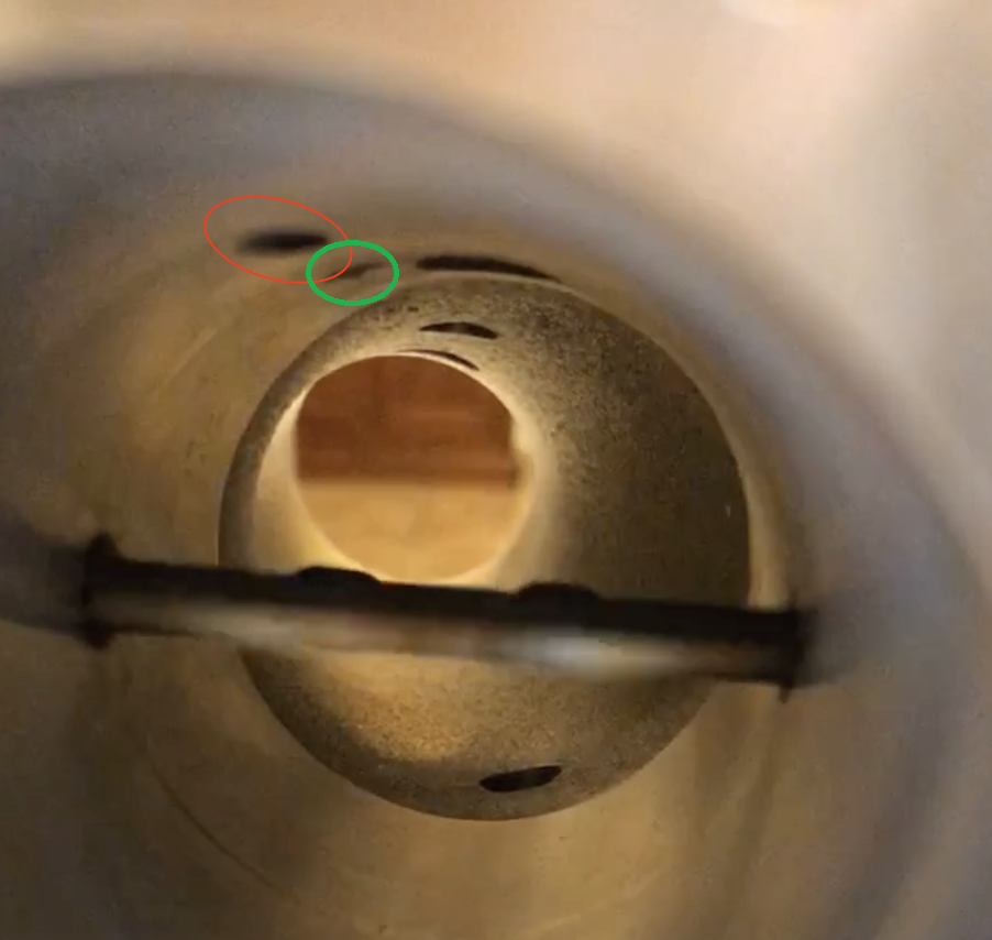
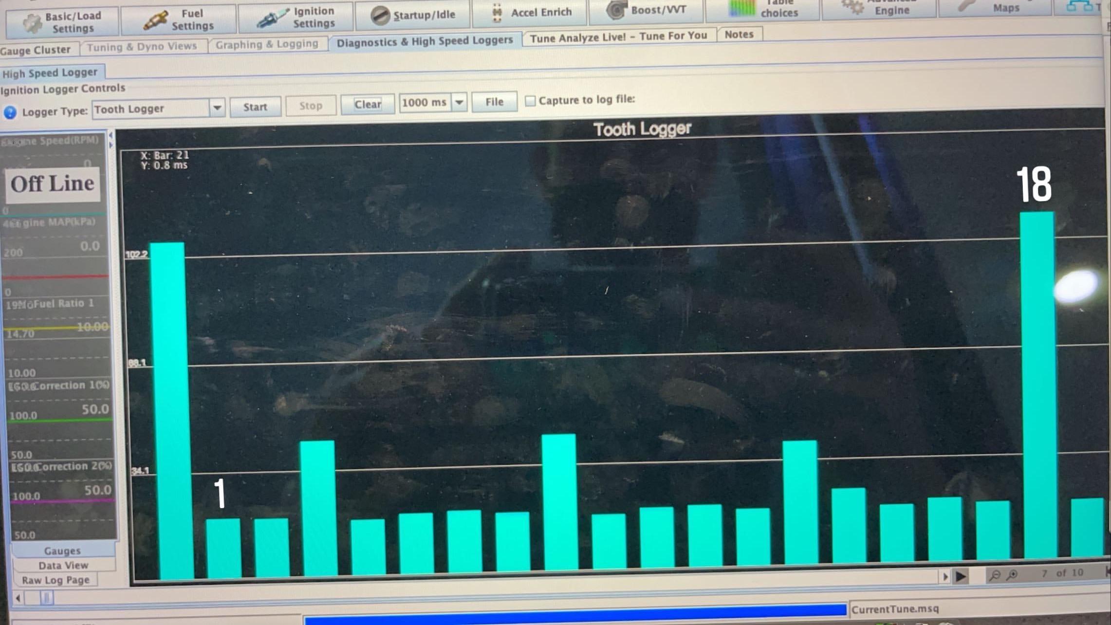
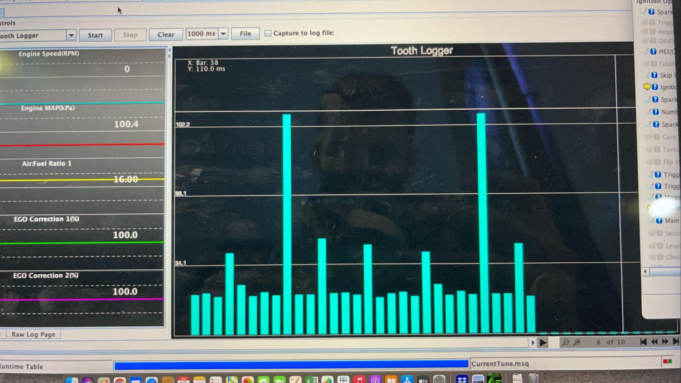
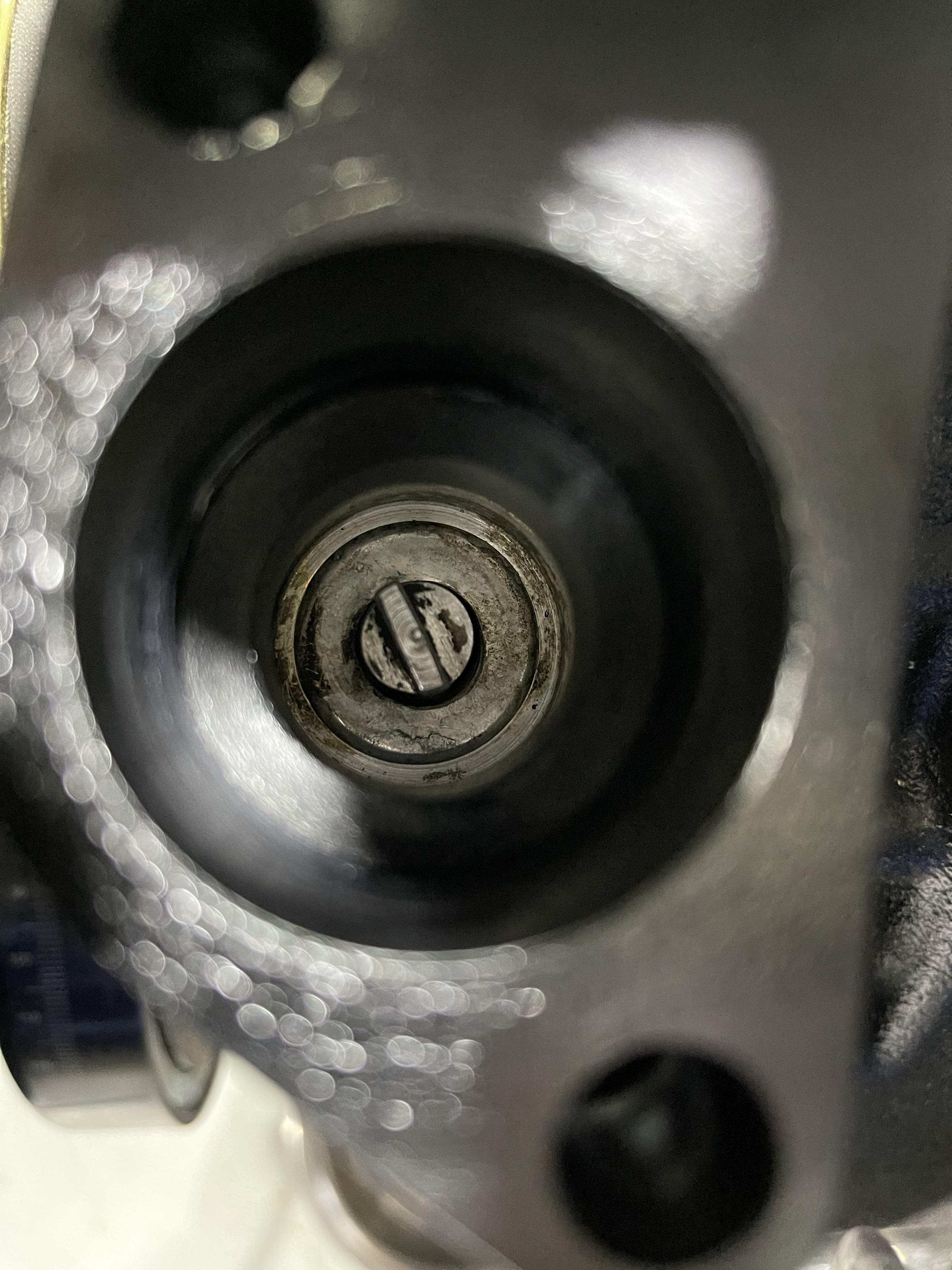
Having this tooth log complete was euphoric after 2 weeks of troubleshooting and trying different wiring, I even extended the shielding (wire + aluminum envelop) to reach the CAS connector as I thought I had noise hiding some teeth. So to anyone using aftermarket Crank Angle Sensor (onesixindustries in particular), always open it and check the VR sensor vs. wheel gap, even in a brand new part that is supposed to be quality controlled, and also blow some air to remove any metal dust... Before: After: Also, I understood how the IAC valve is linked to the inlet port on the Jenveys ITBs. They got one single entry port from the top of Throttle Body, right next to the injector port, but two outlet inside of TB, one going diagonal and on the air side in front of the throttle, the second one is vertical on the engine side / back of throttle, where we have the vacuum. Jenvey provides the IAC valve kit with 6x 2 inserts types, shorts and longs. The short ones could be be used for second fuel input maybe (Nos ?! Ethanol ?!) as it will just go above the diagonal hole (red), but the long one will go deeper and obstruct the diagonal hole, only communicating with the vertical hole (green, next to injector hole), on the correct side of the throttle. SOme of you might have found this ages ago, but I was happy to get my IAC stepper to work so I can refine my idle today and hopefully put the wheels on once brakes and clutch are bled.


-
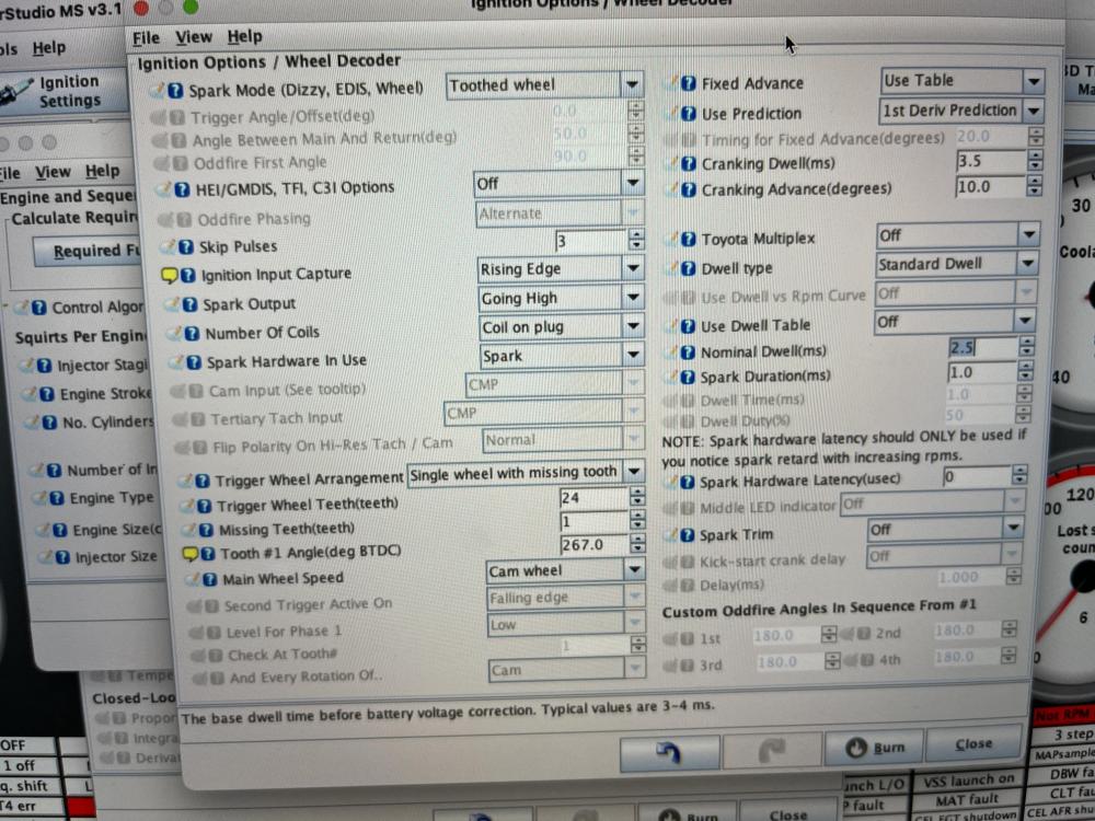
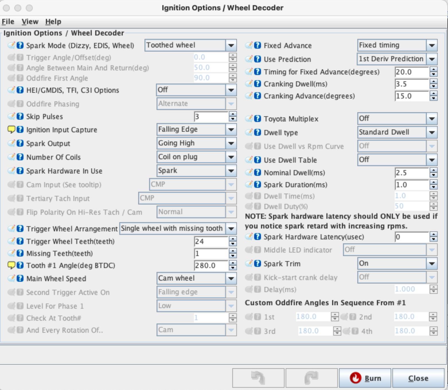
Great day today, the gap between the toothed wheel and the magnet in the CAS was the issue ! Got to love VR sensors. I adjusted it to .5mm and I now got all my teeth on the tooth log (as well as the missing one), and a perfect RPM sync. 😁 Following this great moment, I ran again the coils and injectors tests, check the other sensors and managed to get the engine started. Now working on the idle and timing for fixed advance in order to be lean and match the required fuel calculated by the software. I am at 7ms now (previously calculated at 6.5 ms by tunerstudio, based on engine displacement 2800, number of cylinder 6, injector 480 and targeted air-fuel ratio 14.7). Anyone using the ITB mode for control algorithm primary fuel load and ignition load ? The timing for fixed advance is quite high at 20. My initial tooth #1 angle was 272 and with the above setting, idling at around 750-800 rpm, the light gun shows 290-300 on the harmonic damper.

-
Yes it is around these lines.
-
I use pin D for CKP+ indeed, and so far pin A for CKP-, but might try your setup with sensor ground from MS3 instead of A. You always had all the 23 teeth and the missing one on your tooth log ?
-
I made the TDC with the valve cover off, to ensure both valves are closed and cams up on cylinder 1, so should not be on the exhaust stroke correct ? I'll still try with 273+360 also tomorrow. Thank you.
-
You mean the V1 CAS ? I am not certain, as the V1 seems to have 24 teeth and no missing tooth and the V2 has 24-1. https://drive.google.com/file/d/18emLJTYFfAXeZbeBEE8t25-17feUDXnL/view for V1 https://drive.google.com/file/d/1NEjB-zbjPaCB11_pICNsNU-8pCn6UEe8/view for V2 (This sensor is the same as commonly found on Toyota engines however with a modified trigger wheel. A tooth has been machined off.)
-
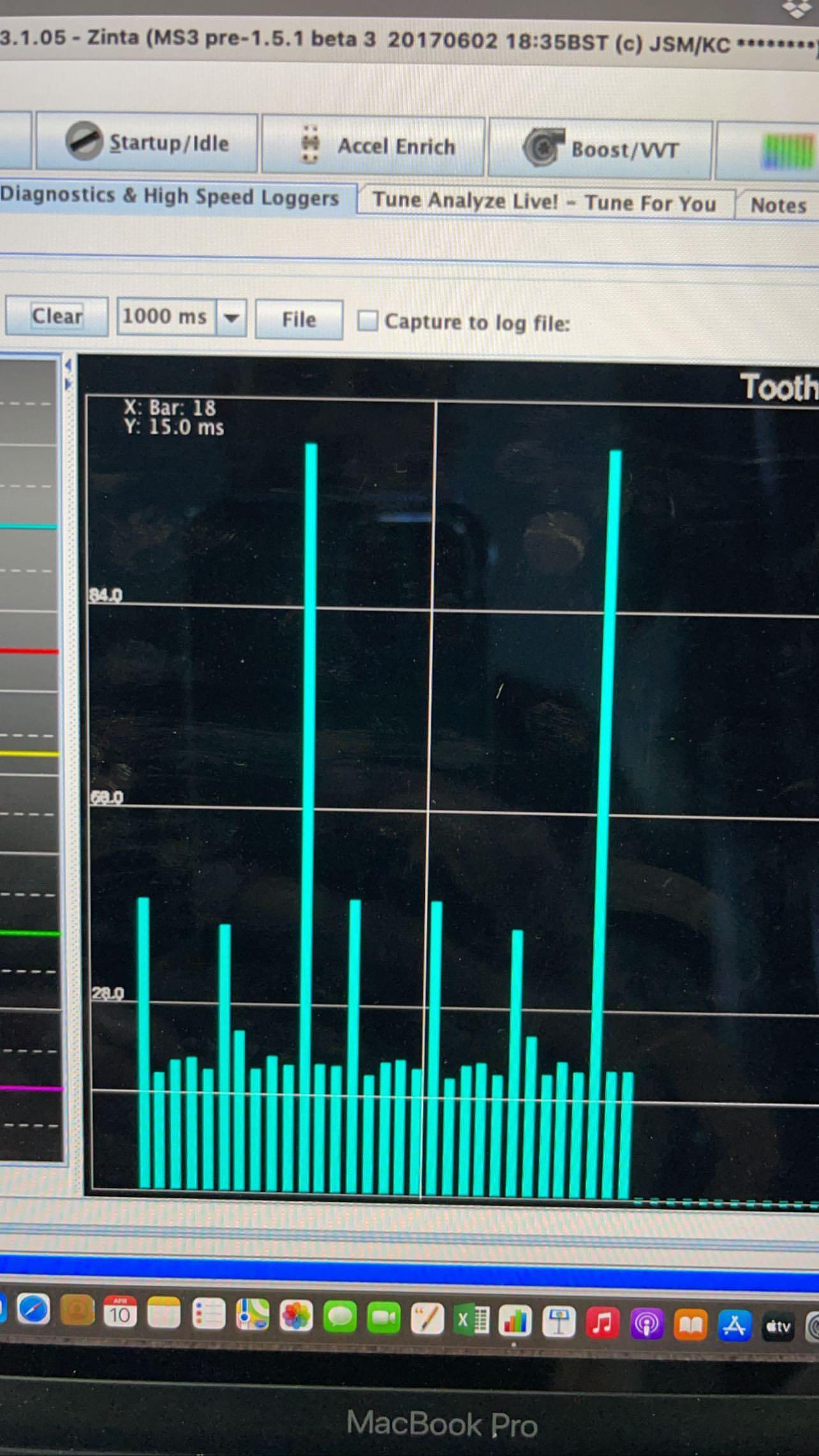
After further investigation, and also trying timing gun to determine BTDC... I still get around 270* Something bugged me from the tooth logs, first of all not 23 teeth and 1 tooth missing, and also a number of teeth that was changing... I checked again my grounding, made sure the CAS wiring was correct and not close to coils/injectors/power wiring, already have my 10k resistor in series with the CAS (between CKP+ and CKP- wires), and still had these odd tooth log, so I opened the CAS (onesixindustries, 400$ piece of scrap ?). To me, it seems like the CAS factory wheel/magnet adjustment was way to big... so I did my best to bring the magnet closer to the wheel, loosen up these 4 bolts. I could not try to take a tooth log today but will do tomorrow morning. Any other suggestions on what could cause the VR sensor reading f*** up / missing teeth that I did not check as above ? Anyone faced the same issue with onesixindustries CAS or similar and fixed the issue ? It would make sense that THIS is the problem causing the RPM to sync and unsync, because my BTDC seems "correct", but as the wheel is supposed to be 24-1 but only send input for 17-1 or 18-1 at the moment, then its obvious the ECU cannot cope and get RPM sync 100%.


-
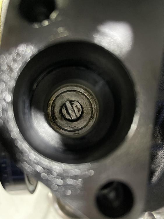
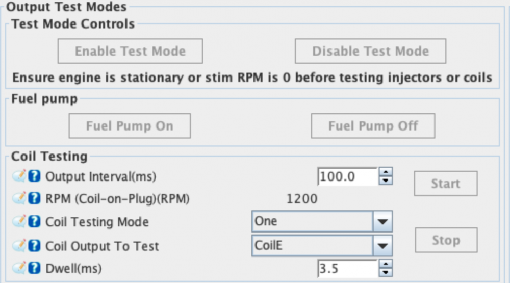
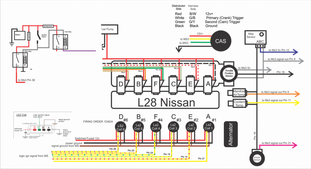
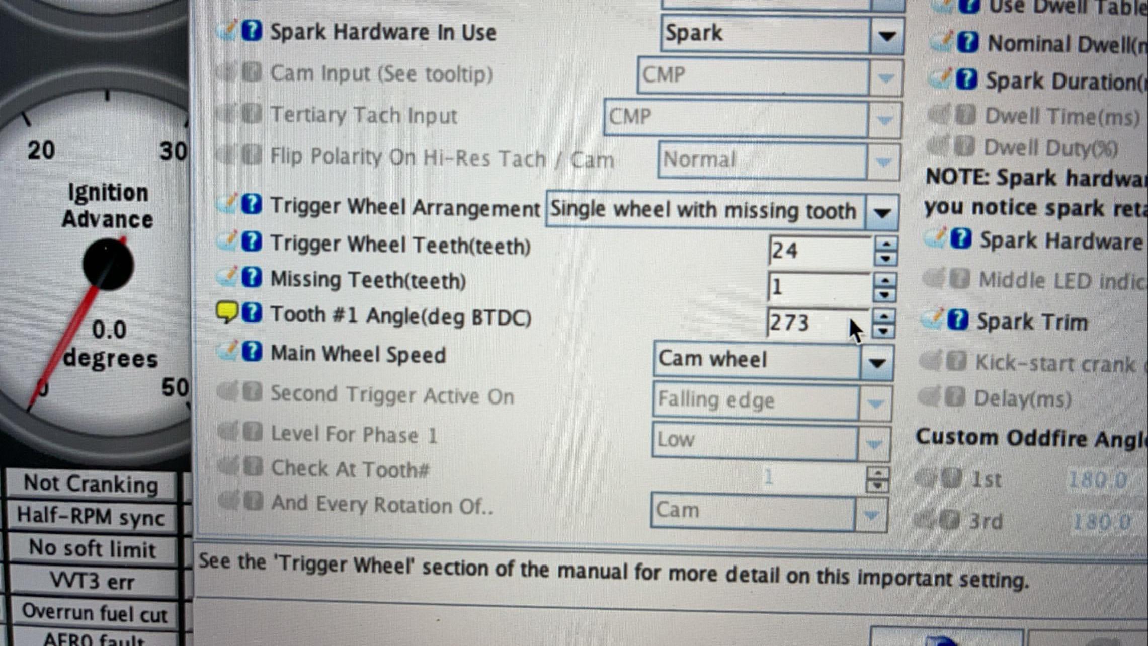
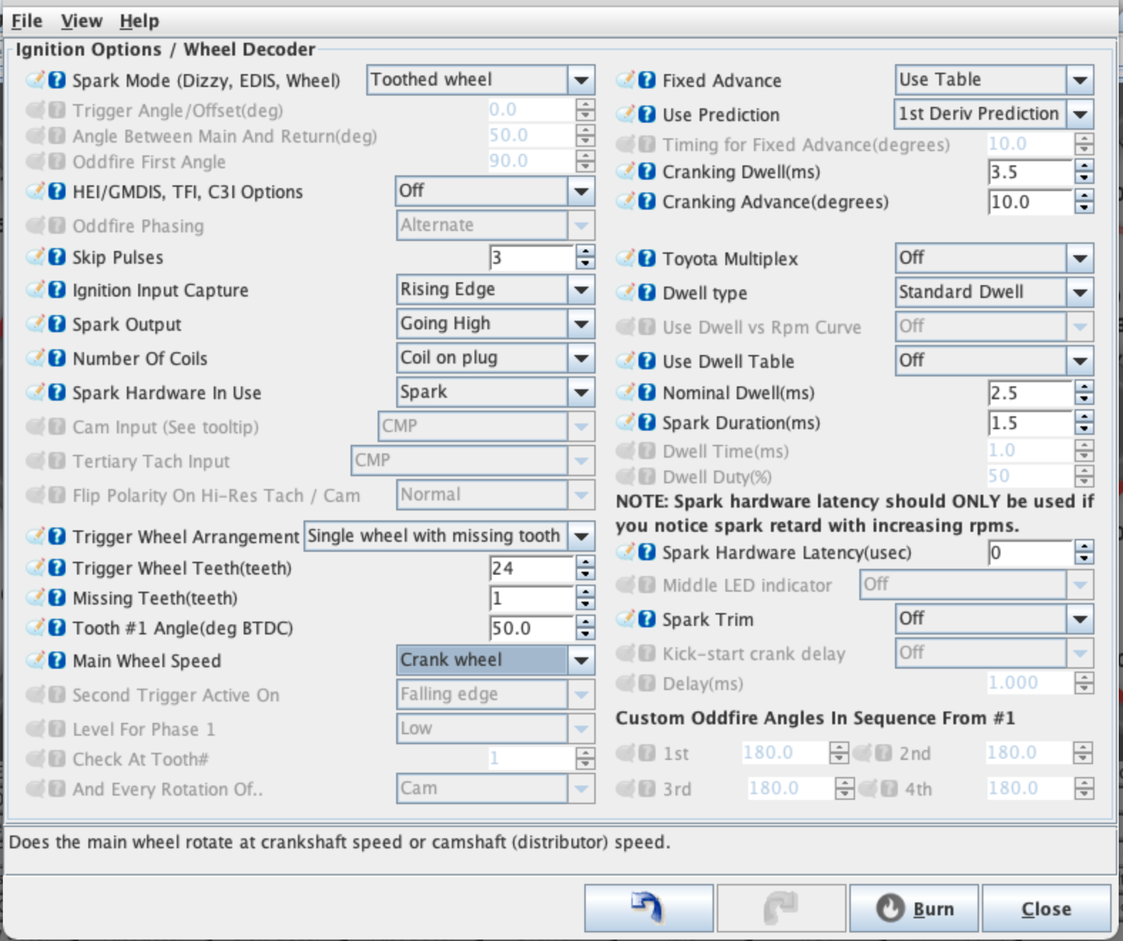
Conclusion on the onesixindustries CAS wiring with MS3Pro: CKP+ to pin D and CKP- to pin A, with pins B and C left unused. The Honda COPS worked their magic and I completed my coil/spark testing. I now work on the timing/advance and obviously getting some weird thing... When doing the engine work and so one, we removed the oil pump and spindle and of course did not put it back correctly. So after manually cranking to TDC with valves cover popped open to ensure of the correct position, we fixed the spindle position to 11:25 small side on the left. Then with the CAS cover open and tooth #1 (24-1) in front of the sensor, we placed the CAS correctly on the block, aligned with spindle, and spun it until the fixation hole was reachable. From this we manually cranked again in order to align tooth #1 to sensor and the reading on the pulley damper was 267* BTDC which seems odd but we followed the method to the dot... Any comments ? 11:25 spindle (engine front on the left) My ignition / wheel decoder are as below at the moment, and I have on and off RPM sync. I loose the sync at the same time as my fuel pump relay clicks and get it back when clicks again, so not quite sure about the reason but obviously linked. I then got an advice from Hussein at Protunerz (from where I got the CAS) to try alternating / semi-sequential and then change "number of plugs" to "wasted cop". Could not try as the workshop was closing... I am also doubting on my firing order, this is what was also in MS3 manual, A1, E2, C3, F4, B5, D6. Video 06-04-2021, 5 52 11 PM.mov
-
-
Again, thanks for your valuable inputs. Had a chat with Matt from AMP EFI and he suggested to wire the CKP+ to pin D and CKP- to pin A, with pins B and C left unused, if not getting my RPM sync then I will try your setup with CKP+ on pin D. He also mentioned I would need to change the setting from crank wheel to cam wheel in tunerstudio.
-
Thanks @wheee! The MS3Pro does not have internal igniters, so I went on the hunt today and found Honda Civic COPs (a little shorter than yours I believe) and a second hand engine harness with plenty of connectors including the 3 pins needed. For whoever is interested in getting a set of 6x DG508 (+2 spares) + pigtails connectors + bracket to install on valve covers 😂
-
@wheee! Could you please share your CAS wiring with the Haltech wires ? Thanks a lot for your help on this, will try to get UF400 coils and connectors locally, quite disappointed in myself following the DG508 lead, thinking they had self ignitor... Will try to avoid them burning =D
-
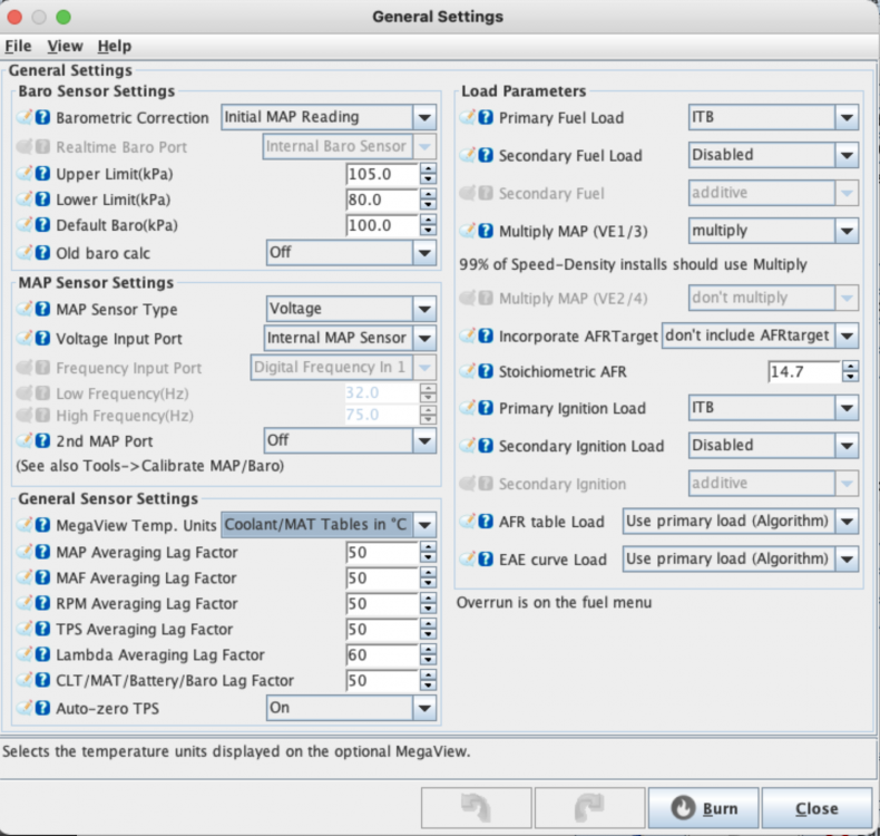
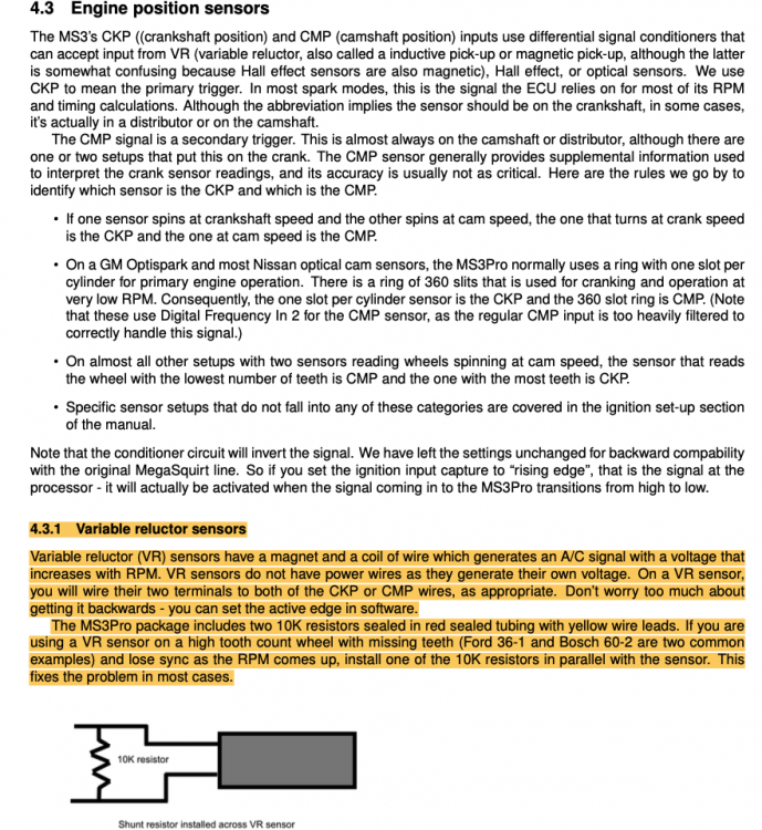
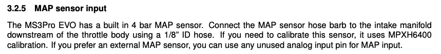
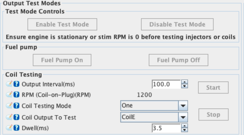
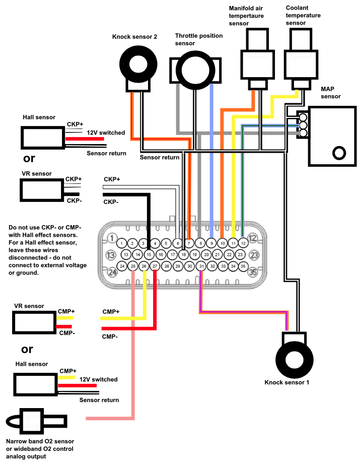
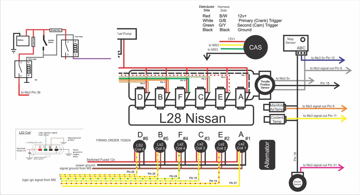
Hi guys, Hope you are well and safe from COVID. Been a while since my last activity on this thread, been busy on the car wiring/ECU setup and obviously bumping in some issues 😁 not a surprise as my curriculum is mechanical engineering... Stupid question 1: From the MS3pro manual below, VR sensors should be wired to the 4 wires CMP+/CMP- (camshaft) and CKP+/CKP- (crankshaft) from the MS3Pro (4 shielded wires from the white connectors) and don't need power or ground wire as they generate themself the power. This is what I have done so far... but I still don't have RPM sync in tunerstudio... Also, the onesixindustries CAS (4 pins connector) is considered as a single VR sensor (as per onesixindustries info), on the Crankshaft? (because crank angle sensor...?). So should I remove the CMP+/- (camshaft) and put power/ground instead ? or remove CMP- and CKP- and put power/ground instead ? I found a wiring diagram for L28 that shows this latest option, but I don't know if thats correct and would rather not burn the CAS. The wiring diagram below shows a CAS with CMP+, CKP+, 12V power and Ground... Should I follow that ? Stupid question 2: I have a set of DG508 coils on plugs with 2 pins connectors (not like the LS2 above setup above with 4 wires), so the wiring should be 1 power source from the fuel pump relay (as mentioned in the MS3 manual) and 1 signal source the MS3 ignition signal (A-1,E-2,C-3, F-4,B-5,D-6), I don,t need anything else correct ? The 12V power comes from the fuel pump relay all the time, and is only "released" when the signal from the MS3Pro is sent to each particular coil, then the coil itself generates the huge voltage for the spark ?! Or am I wrong here as well ? Respecting this setup, when running my coil test (on the connector only, disconnected from the coil, and using a small light and wires) I have power all the time (light is ON), independently from the coil output to test (obviously Fuel pump is On), meaning if I test coilA in tunerstudio, connector to coil A gives light, and if I change for test coilE, connectors to coil A still gives light... Am I wrong on the wiring ? or on the software part... I was told by AMPEFI to setup as below: On the bright side my injectors tested correctly, my IAC valve seems to be responding too, the TPS is calibrated and the IAT (I don't have MAT with the ITBs) is a GM type from Protunerz, so all is good and clear. Also, having an IAC valve (came with the ITBs kit from Jenvey - link), a built in MAP sensor in the Ms3Pro, and running itbs naturally aspirated, I don't need a MAF correct ? I have a weird temperature reading on the CLT oscillating between -20 C and +80 C (its a VDO sensor that was on the car, cannot find any info for its calibration), I will probably have to do the old school way with water, even-though i found these online: Please help me, because its a real frustration to be looking at this without having the sound...


-
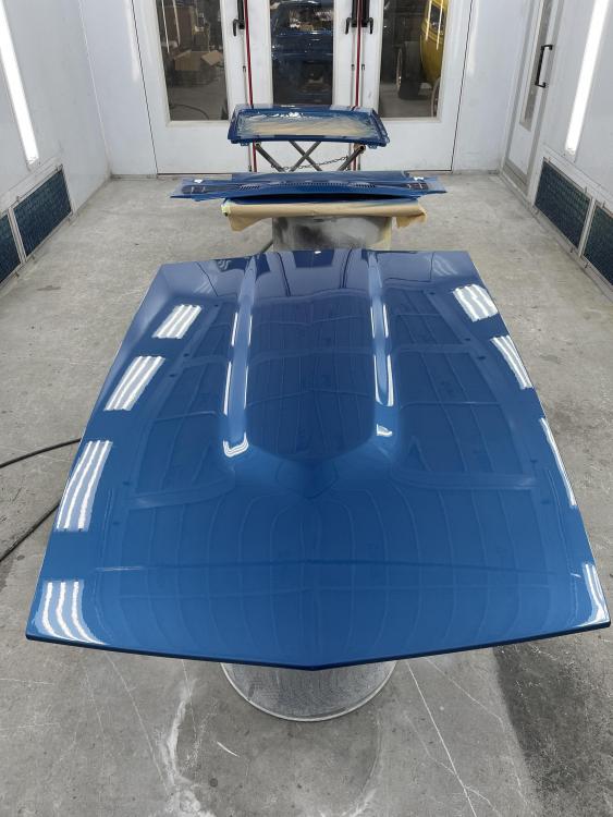
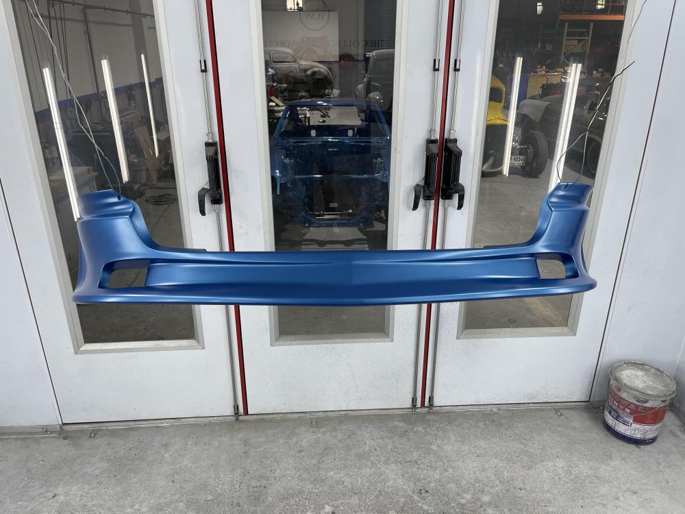
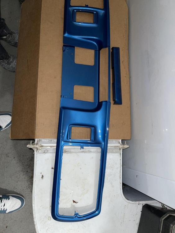
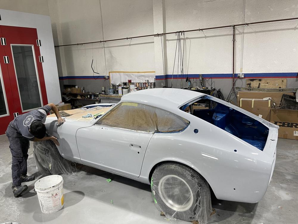
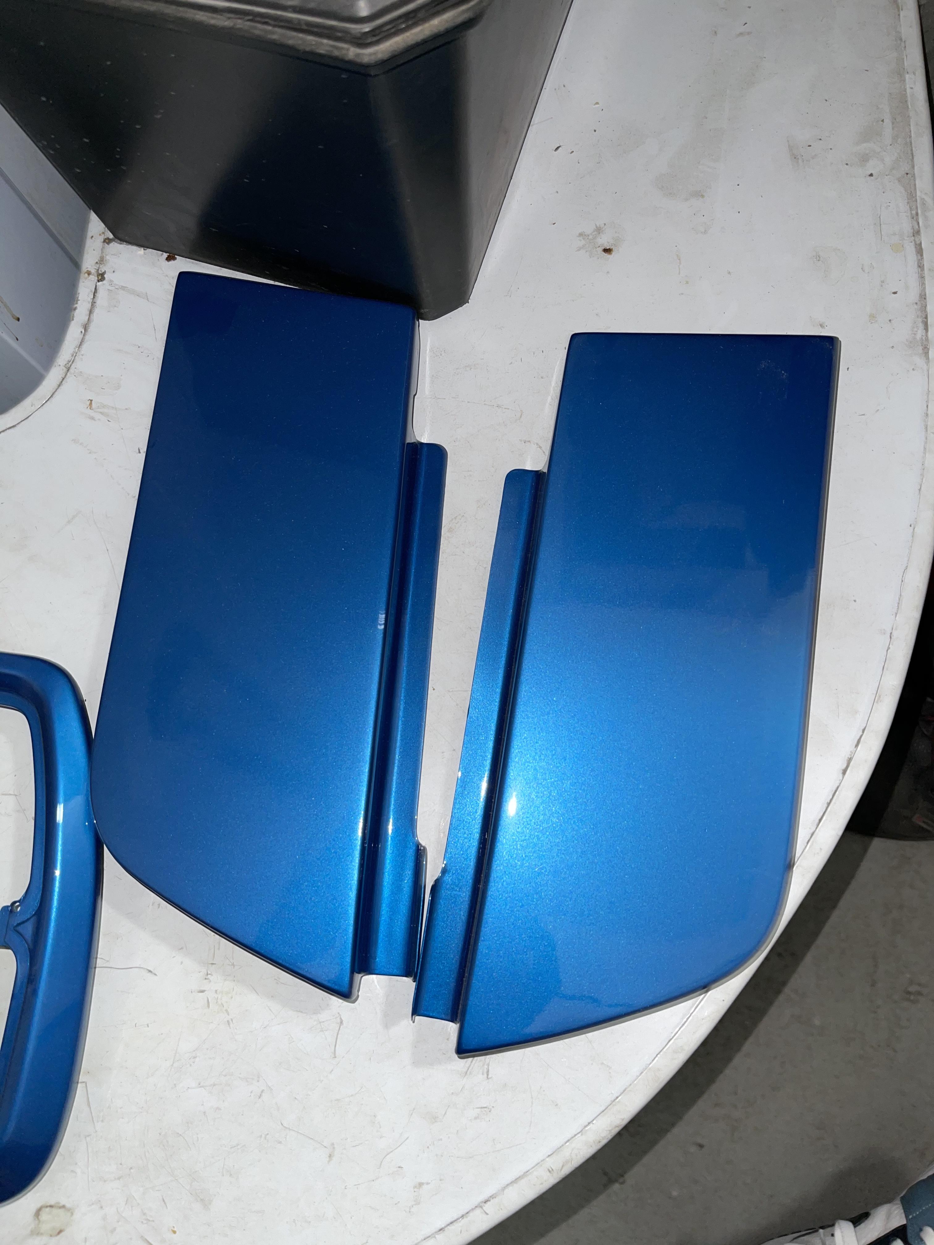
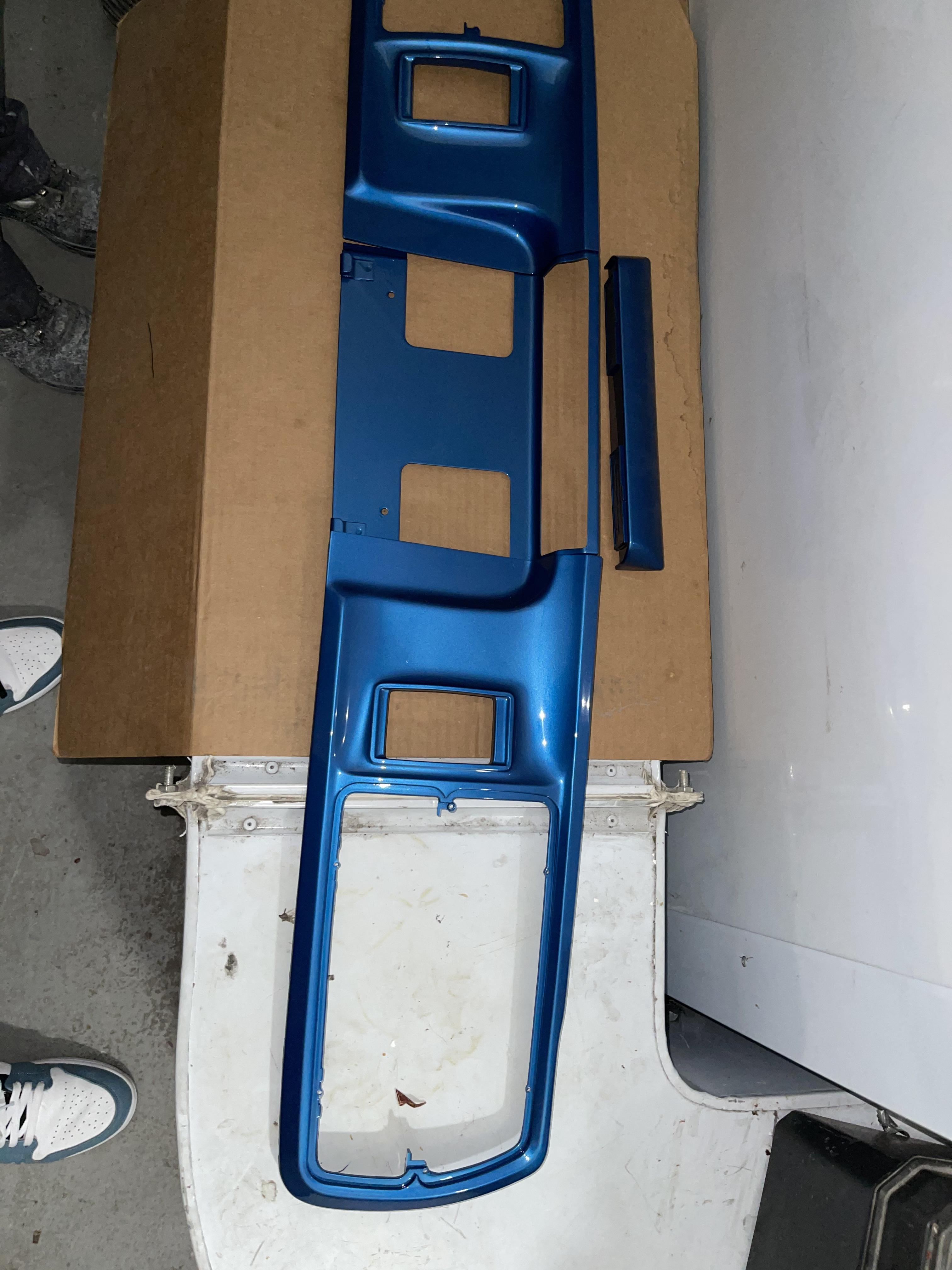
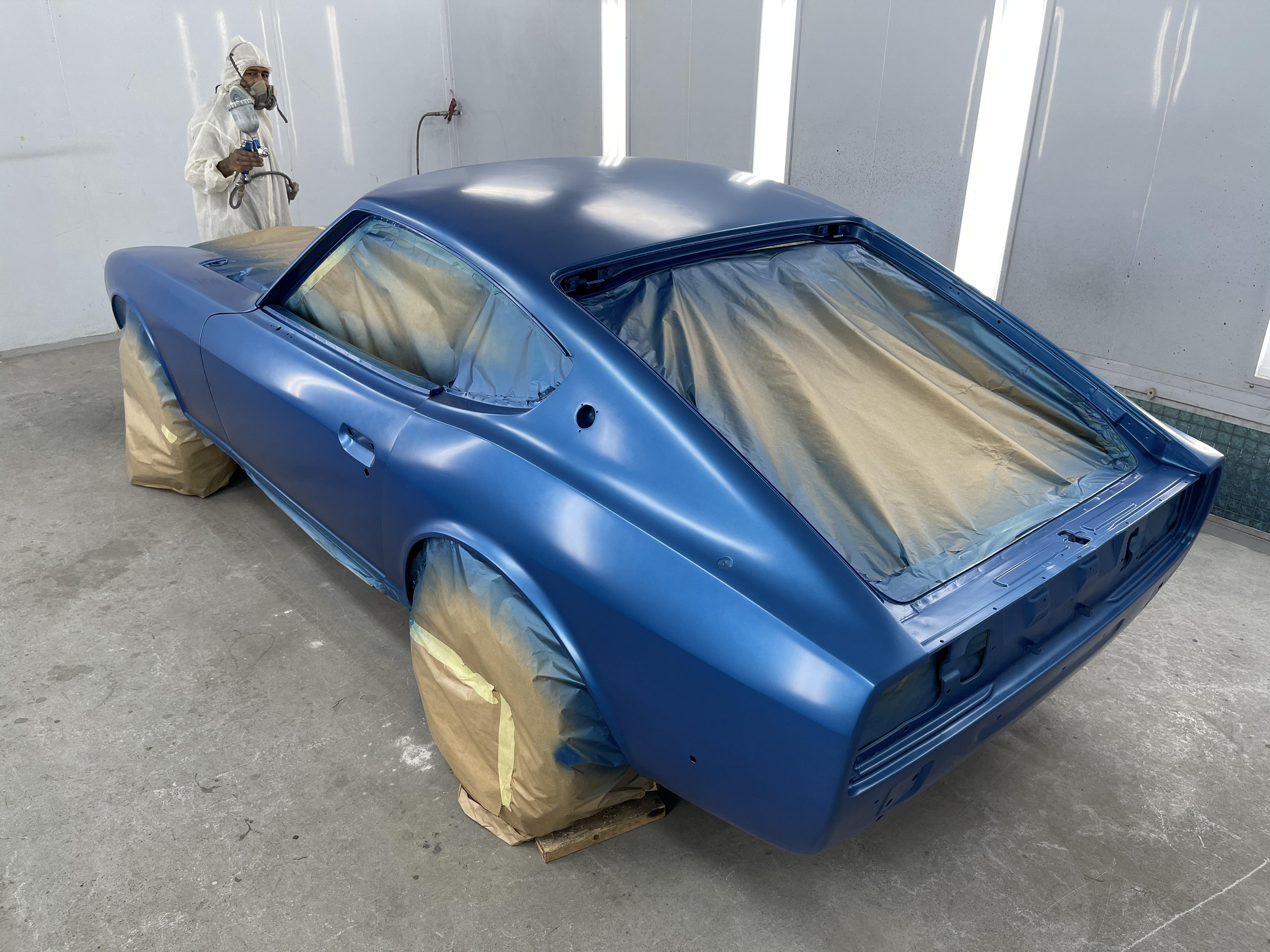
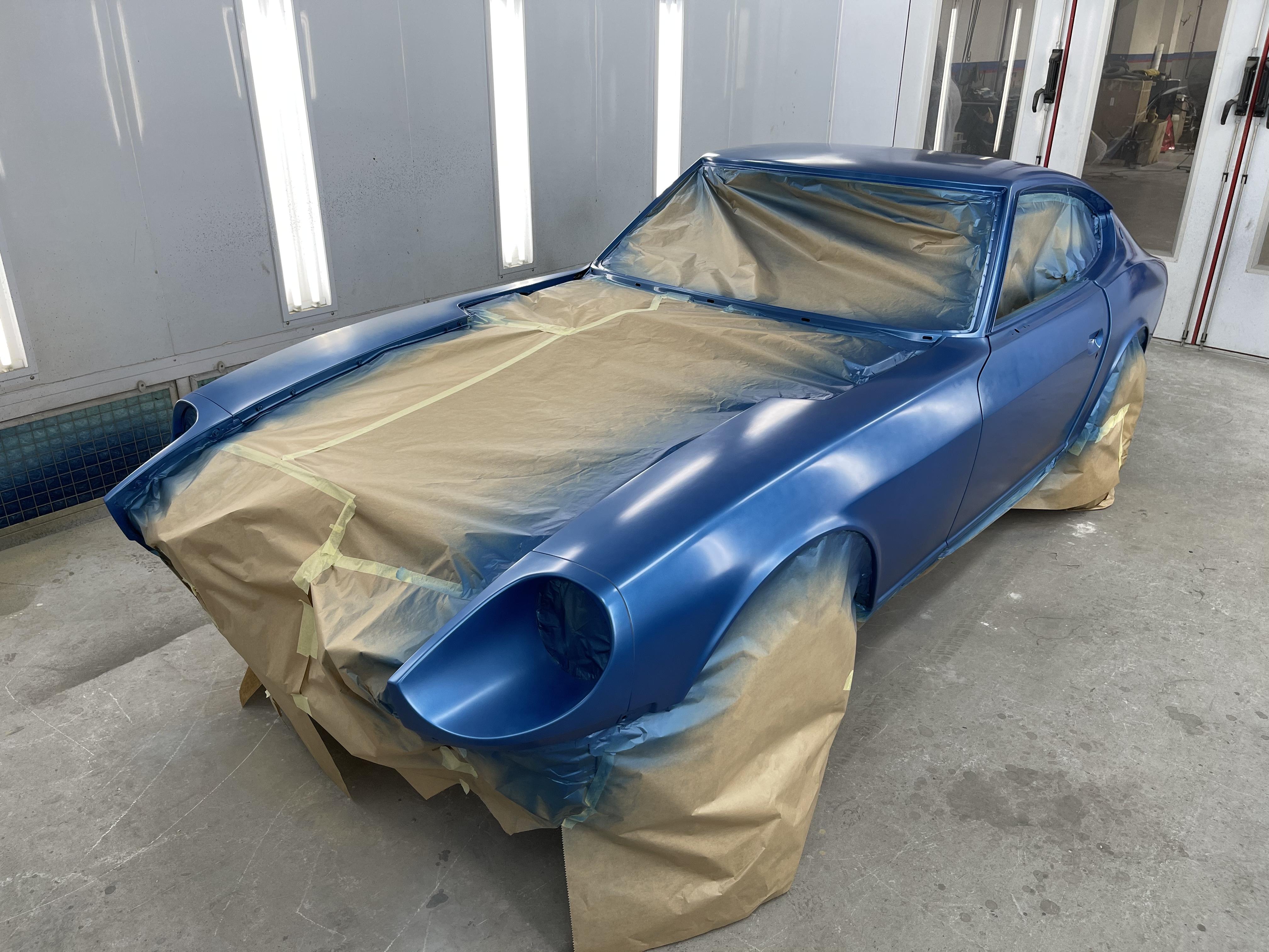
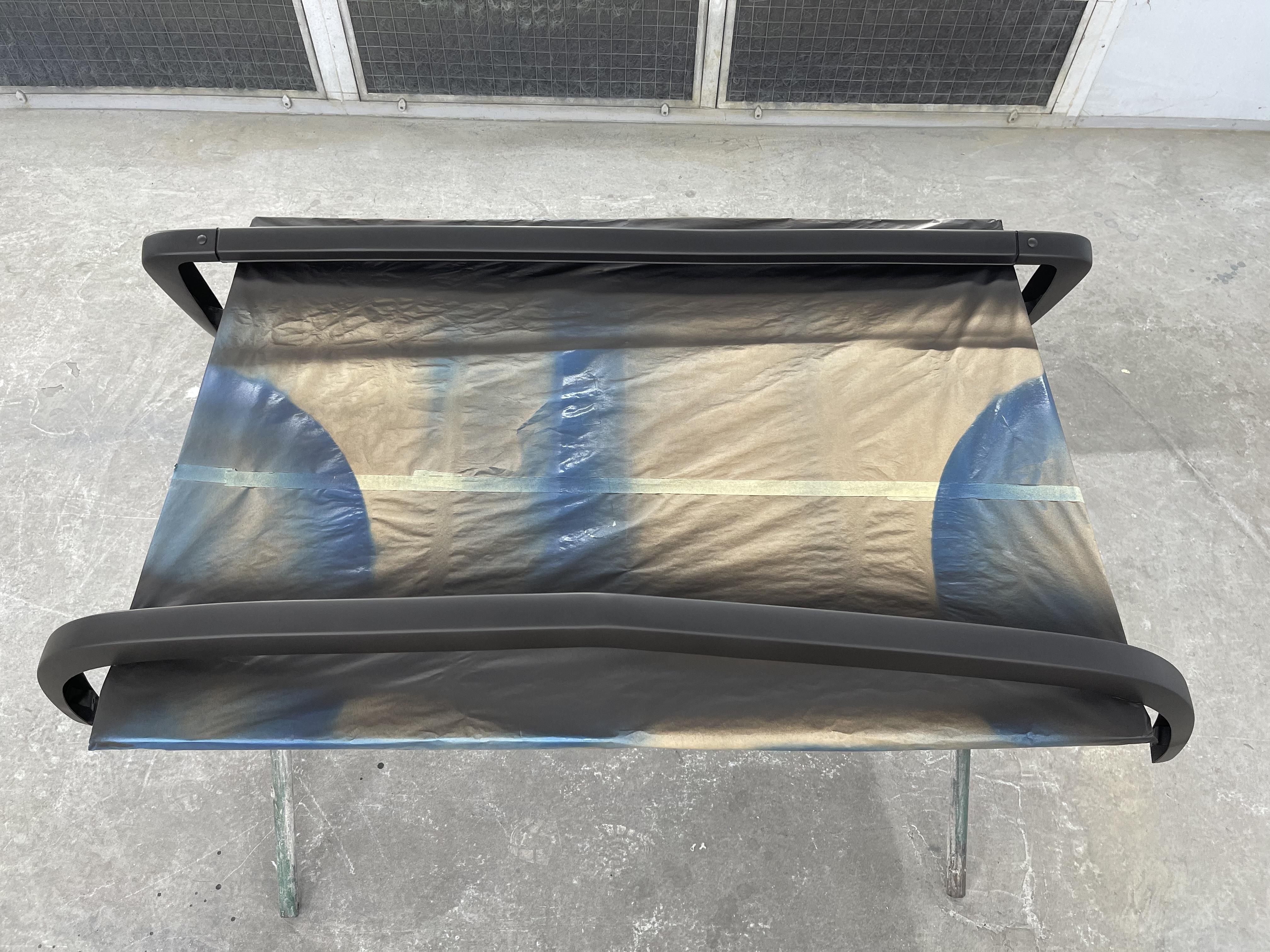
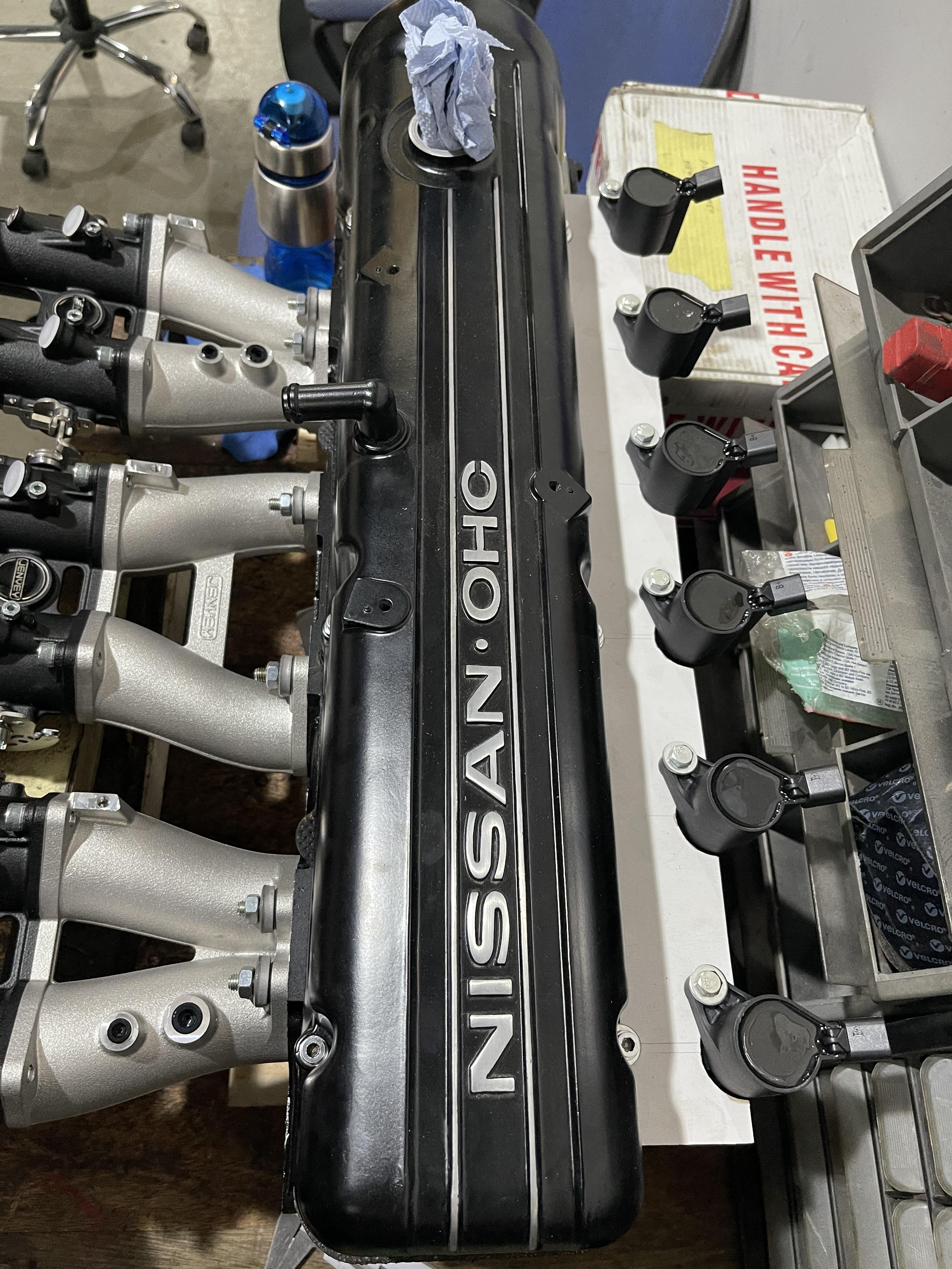
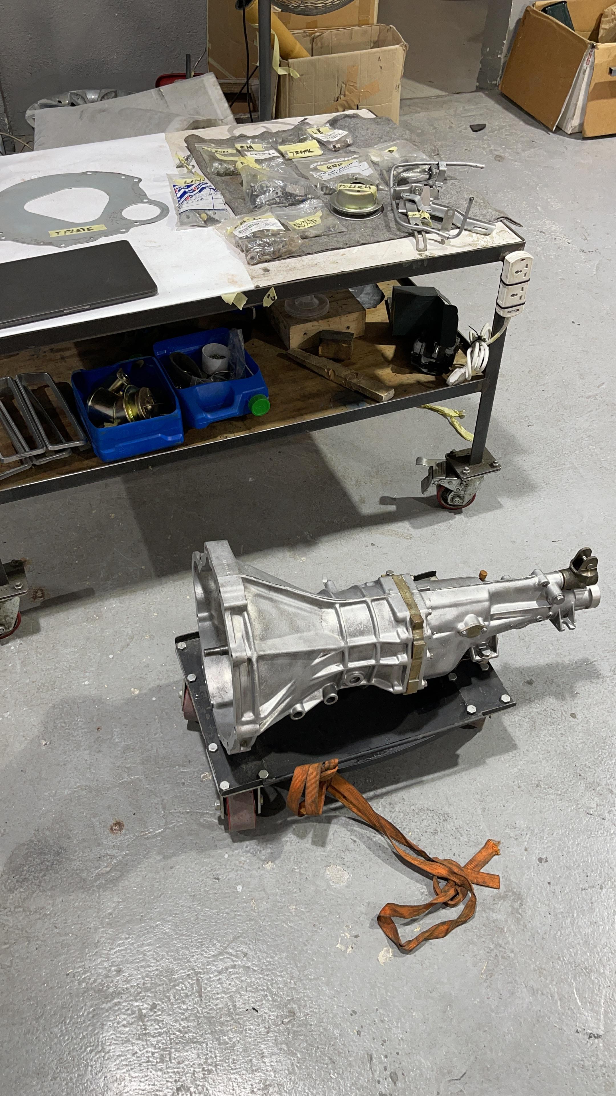
Good morning everyone, Zinta was finally painted over the weekend (mostly on Thursday) and... She is stunning ! Last wet sanding before entering the booth for cleaning and prep. Below picture is before the clear coat, I hesitated to ask them for the mat/frozen look with a specific clear coat, but I still wanted to have the same original DAT307 from when she left the factory in 1976, so I went with the regular shiny clear coat (pictures soon as there is a surprise coming with it). Air Dam before clear coat and bumpers with primer only (all the holes from the bumpers were welded and the brackets adjusted to reduce the gap, so they sit closer to the body): Hood, Trunk, inspection hatches and tail light/license bracket after clear coat: I finally receive my head bolt for the engine today (ordered 3 weeks back from Zcardepot, through eBay), so the engine rebuilt can start ! In the meantime, been working on the individual coils support and the ITBs air filter support, will only do an intake ports matching but no polishing. The 81 280ZX 5 speed gearbox also got cleaned and made ready for the final assembly !


-
The labor cost comes from you, you are the one generating the value 😎 Please send any S30s by all mean, I ship them back within 6 months =P
-
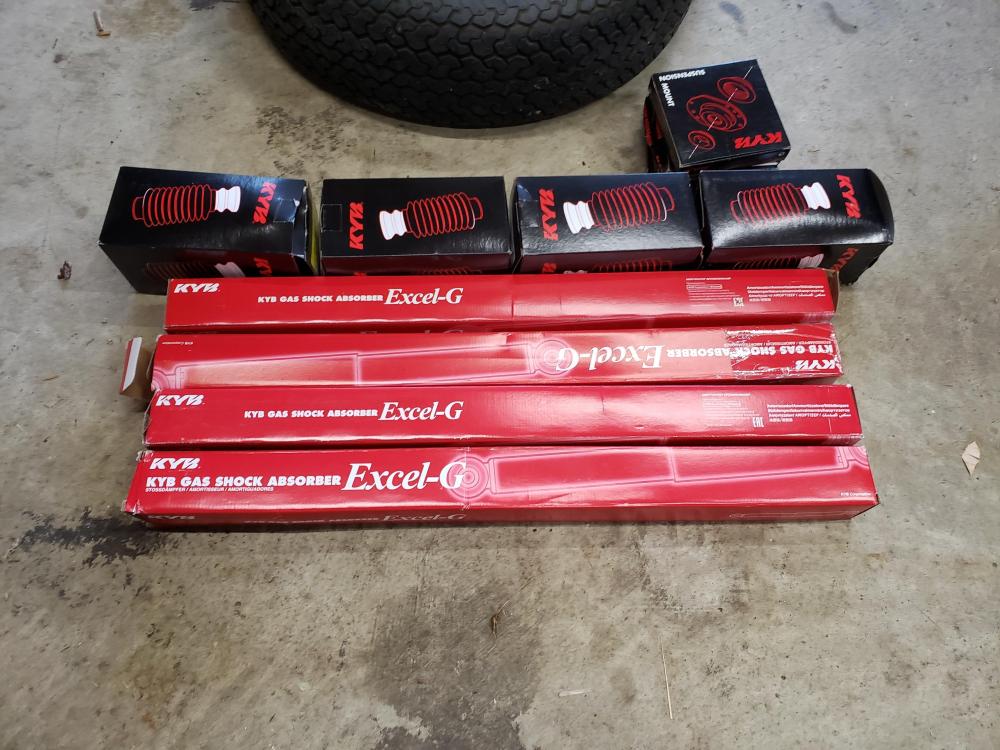
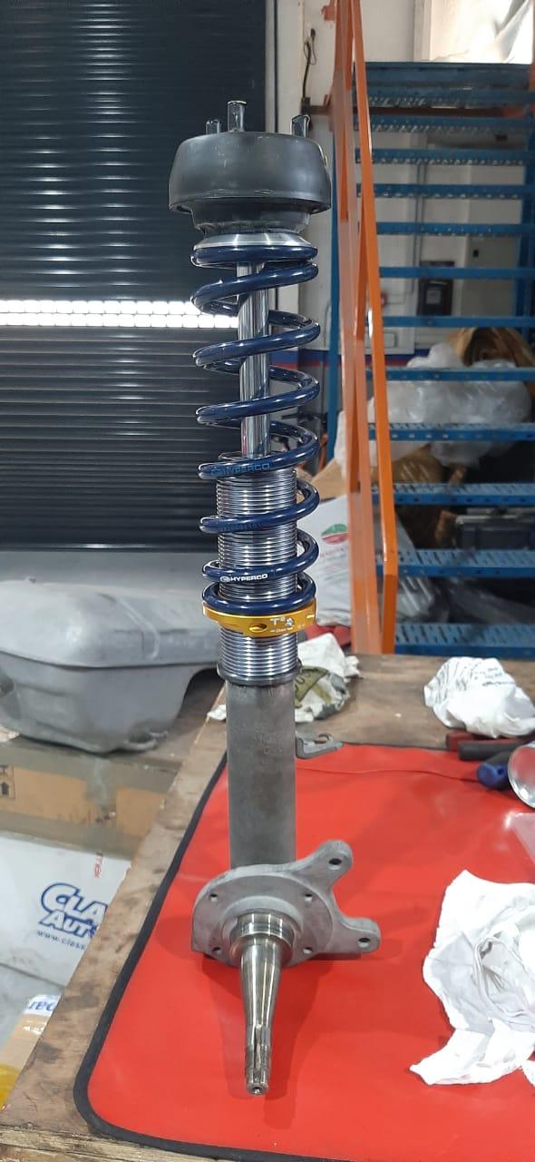
That's correct, they did not fit inside the new Springs and would have required some cutting for the bump stops.
-
I remember a show on Netflix with Michael restoring and flipping many army vehicles and even a plane from WWII. Same kind as rust valley restorers. The video you are referring to is this one correct ? https://www.youtube.com/watch?v=iE8E-2VNv9E. The advantage they have in eastern Europe is the access to a lot of army vehicles, so that's how they source their parts and cut cost. Also, its always easier and cheaper to work with body filler / bondo than actually changing and reshaping the metal panels, that's why my car looked great originally, but under than paint was another story...
-
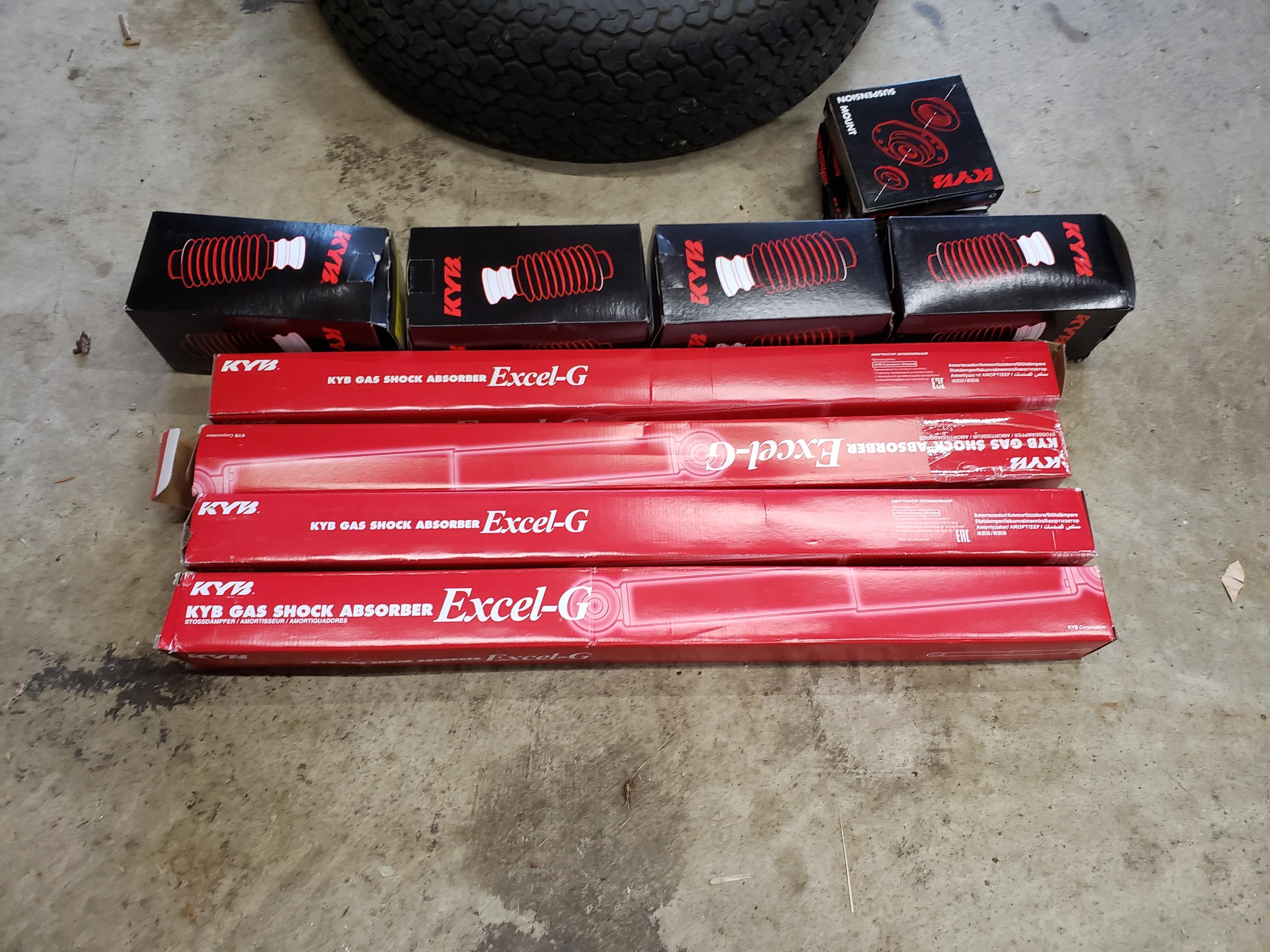
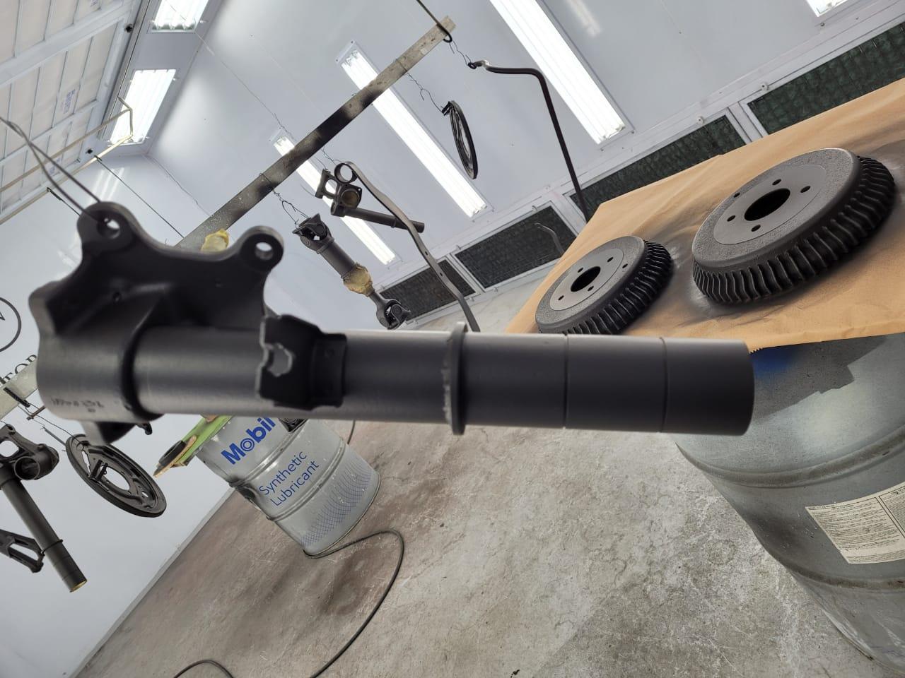
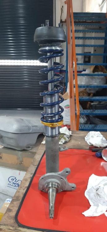
I had 4 brand new KYB Excel-G as part of the spare parts coming with the car, so I am giving it a shot ! Then the T3 weld-on coil-over kit to be fitted on the original shock housing. We machined and welded metal support ring to sit the coil-over kit (original ones from T3 was not the correct diameter) and made 2 grooves to keep the O-rings in place. I am quite happy with the color theme, now just to confirm if the driving sensations are as pleasant !
.thumb.jpg.af242f7a5f07e01321f85c07cf0cb13b.jpg)


.jpg.e49ab641773c7632d9baccdfbdcf4b8f.jpg)