Barefootdan
Free Member
-
Joined
-
Last visited
Everything posted by Barefootdan
-
 I may have missed it, but is there a reason to do this in the car rather than pulling everything out? Just curious 🙂
 -
Nothing quite as good as something brand new! You also gain immense knowledge of your wiring circuits. Countless times I have ran into an electrical mishap (be it my fault or a faulty part) and I can still think back to when I did my wiring harness to diagnose the issue without the need for diagrams.
-
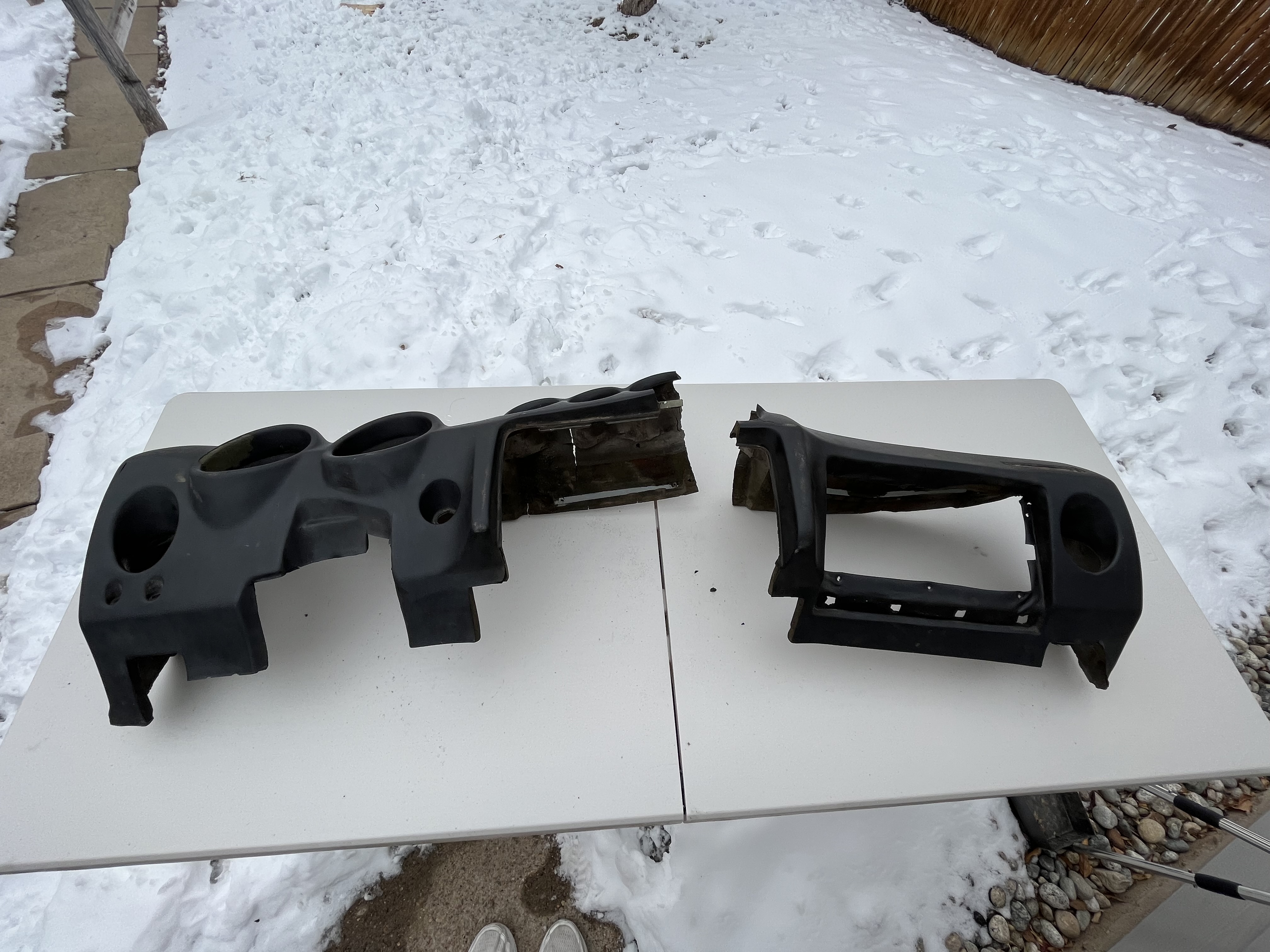
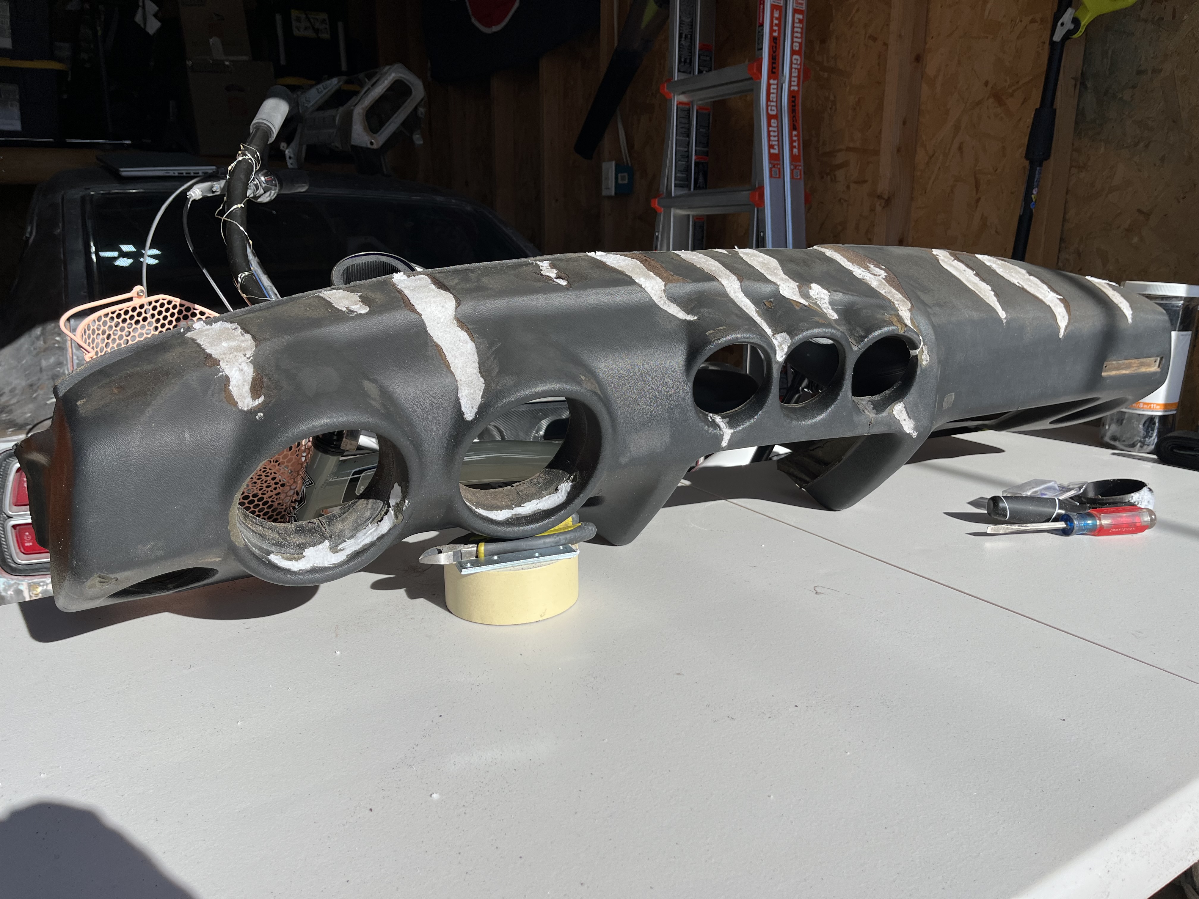
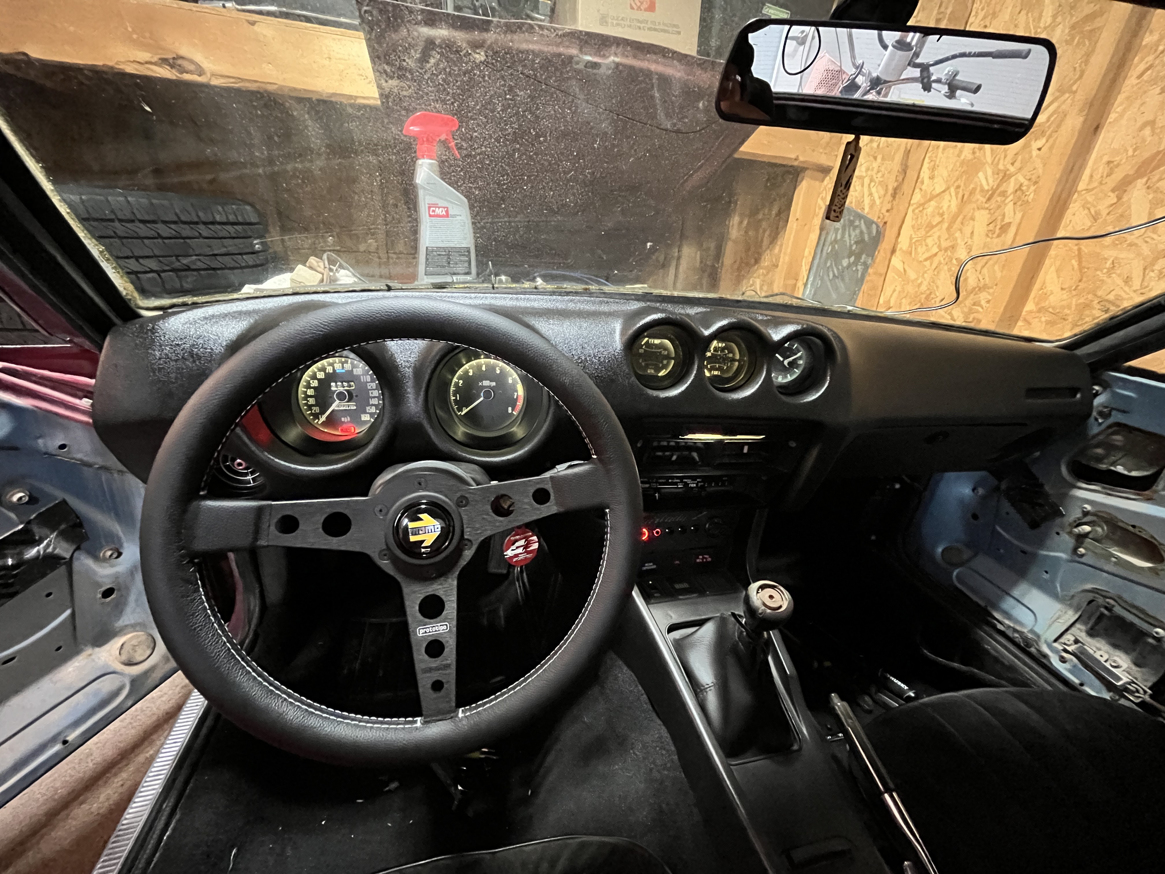
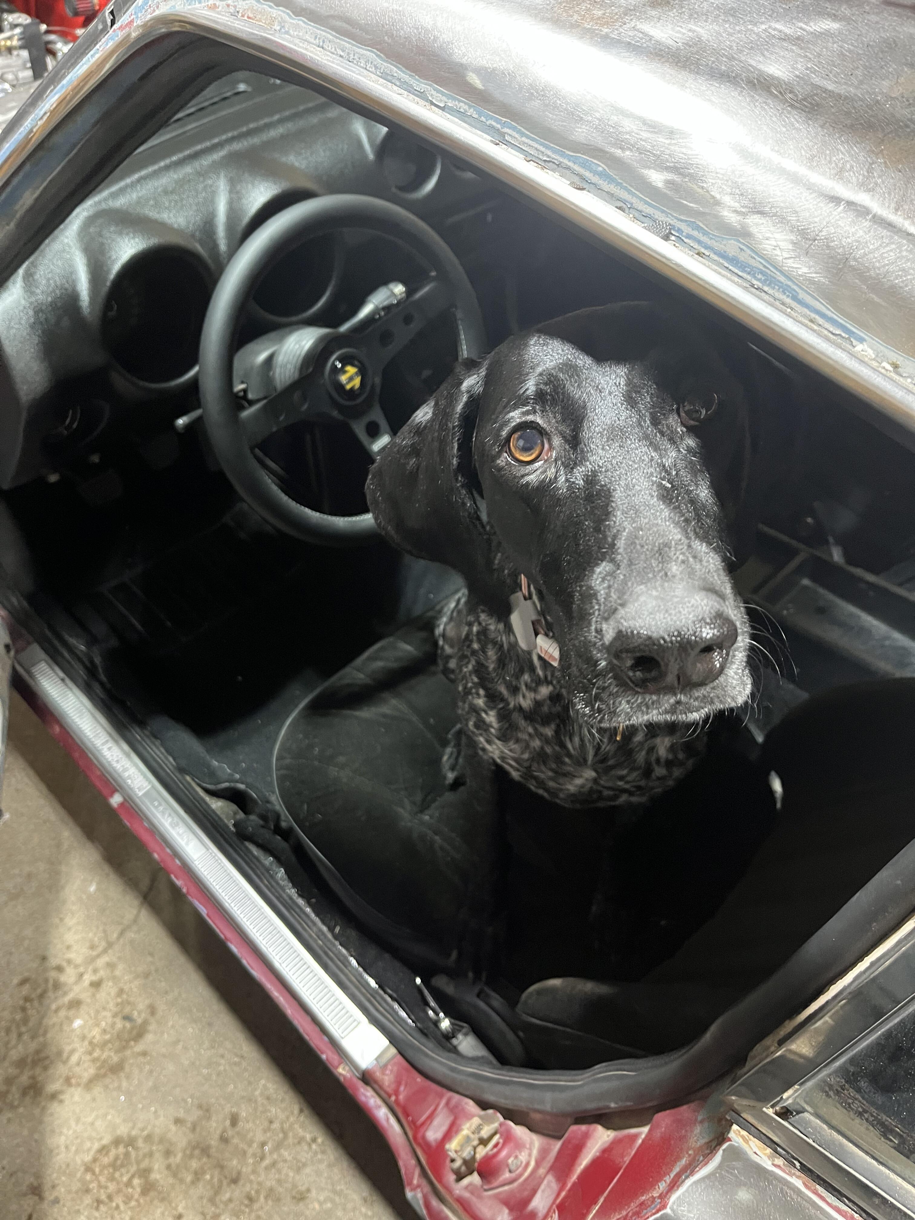
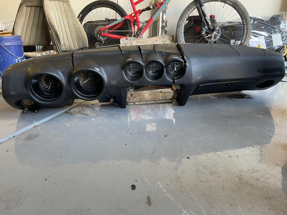
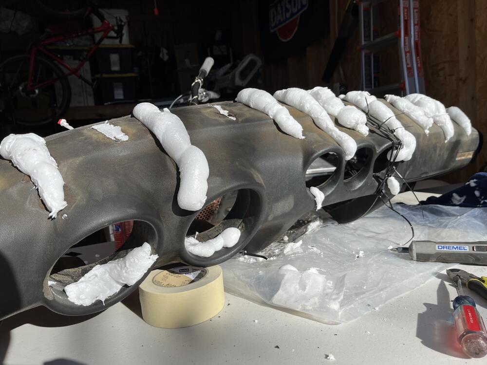
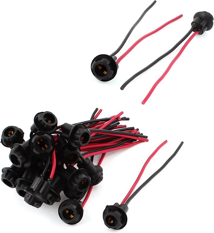
Dove into restoring the dash this past couple of weeks. It was destroyed by the Arizona sun. I didn't photograph the process too much because, honestly, I didn't have high hopes on it turning out well. Here is an old photo of what we were starting with: Typical cracking for a Z dash, but boy was it brittle. My initial plan of attack was to get it off the frame and smooth out the ridges and cracks. But I was in for a nice surprise once it came off the dash frame: Little did I know, the frame was holding together my now two piece dash 😅 The crack near the third gauge pod made its way entirely through the dash. Now I needed to fuse these back together before I could start any sort of work. I also looked into vintage dashes or other reproduction/professional repair options but the cost was just too much at this time. I told myself to try fixing what I have first, then if all else fails, a reproduction dash is always an option. I grabbed some spray foam (loctite brand) and a couple strips of plastic to act as a "stitch" beneath the foam for the two pieces of dash to become one again. After "v" shaping all the cracks and smoothing out the ridges, I foamed everything together and used a jig between a couple of the mounting points to hold the two pieces of the dash in the correct spot. Note all my zipties in the photo below trying to make sure I didn't move the critical bond. After a good 36 hours of drying, I finally mustered up the courage to undo the zip ties and see if everything held. And surprisingly, it did! Sturdy enough to bear the weight of itself from one side even. Success! I now had a dash and no longer had dashes. I began to cut away at the foam and sand smooth with an orbital sander. It came out surprisingly well. The foam feel is excellent. Soft to the touch but firm enough to hold shape. I imagine this is how a good condition Z dash would feel. Unfortunately, this wasn't the end of my road blocks. If you look closely at the crack near the third gauge pod, my jig didn't take into account the transition between the two dash pieces. So while they are the correct distance from each other, the expanding foam must've made its way between the jig and the right piece to cause it to flare up slightly. Not a huge problem as I could sand, filler, and smooth it out. But something to note for future me. I started to work the dash to ensure all nicks and minor cracks were taken care of. But it was endless...I would fix one, but the stress would cause another. I could cause a crack by just pressing down on the old foam fairly easily. Pricing out the cost of materials for filler, skim, paint, etc. I started to look into dash caps. I know, dash caps are not a good permanent solution. But who's project car is ever permanently done? 😉 I did some research on peoples horror stories of warped caps or il-fitted gauges, glove box, etc. Some don't even match the OEM color. Luckily, every time someone brought up American Dash Caps, it was always positive. So that is the route I went here. Ordered up their full face deep cut cap and optioned to paint it satin black with SEM. Overall, it was a fairly decent cap. Some of the trimmings were rough, but easily cleaned up. They provided the silicone and an 18month warranty if you follow their steps. Simply apply the silicone 1/2" away from all edges and openings. It feels weird not applying silicone to the middle, but I bet this helps with expansion and contraction. I did need to sand a couple edges down for a snug fit. And here we are now! So much better than before. The photo makes it look very glossy, it is from the garage lights and just wiping it down after install. The true finish looks much more like the right side, satin. It is very close to the OEM finish in my opinion. While the dash was out I updated my gauge lights to white LED in a T10 socket. Almost half of my original plastic sockets were broken or missing tabs. Picked these up and the rubber socket allows for a snug fit with minimal trimming (of the socket itself, not the gauge). I also cleaned up the dash wiring harness, installed a momo wheel I picked up while visiting in Japan! Cleaned up my gauges inside and out while I was removing the green lenses. Couldn't get that darn clock to work.... Everything is slowly coming together for the interior. Next up is some door cards and a new carpet kit. Not a huge fan of the one piece molded carpet. Going to look at Newark or Chester and Herod for my next kit. I'll leave you with a pic of my helping hand in the garage. She's much more willing to be out here in 40 degree weather as opposed to the 100+ degree Phoenix summers 🙂


-
Holy smokes time flies. Been so busy lately and havent had much time to work on the Z. Arizona summers suck the fun out of working on a car. Also moved from AZ to CO and still getting settled in. The Z made it here in one piece (via delivery of course!). Do carburetor jets need adjustment from altitude? I gained about 4K feet of elevation between Phoenix and Denver.
-
I used weather pack in my harness and I’d recommend them. Easy to crimp and pin…and de-pin! The only downside to them is they’re bulky. I used the 280 series if I recall correctly and the 6 pin isn’t small. I do know they have slimmer series though up to 12 pin I believe. But for the large bulkhead connectors I used a molex style. Deutsch has some nice connectors, especially if you want the whole chassis to be the same connector style. Definitely get a quality crimper!! For wiring I went GXL. I felt it provided sufficient coverage for regular driving. 11 colors was enough diversity for me to not get mixed up. But I did remove alot of the OEM options (door lights, buzzers, safety, etc). Wirebarn was a good source for this. Check out my build thread for more details on it and feel free to ask any questions!
-
I took apart the rear suspension again to loosen it all up. I was sure to tighten in the correct order and with the weight of the car on the suspension. I feel that this did help quite a bit! Although, I am not sure if my eyes are playing a trick on me or what, but I think I still see some toe happening. I may need to do a quick and dirty toe measurement with some plates to get a better idea! But for now I am moving on until I can get my hands on new wheels and tires. Other fiddling I did was fixing my fuel gauge. It was always showing empty and never even budged when I turned power on. I started to diagnose the wiring and was just about to pull the gauge when I found a good post suggestion. Grounding at the connector near the fuel tank will simulate a full tank of gas. And funny enough when I did this, the gauge started to come to life! It was definitely sticky and jumped across its sweep until it came to Full. I think it just needed some OOMPH to get it moving 🙂 Glad to see my fuel amount now!
-
@SteveJ Might have a lead on this. I know he worked on finding a good solution for the door seals!
-
I’ll give it a shot! Visually it looked okay but I black bushings with black chassis paint I could be off. Did you tighten the large bolts first or the two smaller carrier bolts? If I recall, poly bushings don’t care about the order of operations but I’d it’d just add some peace of mind.
-
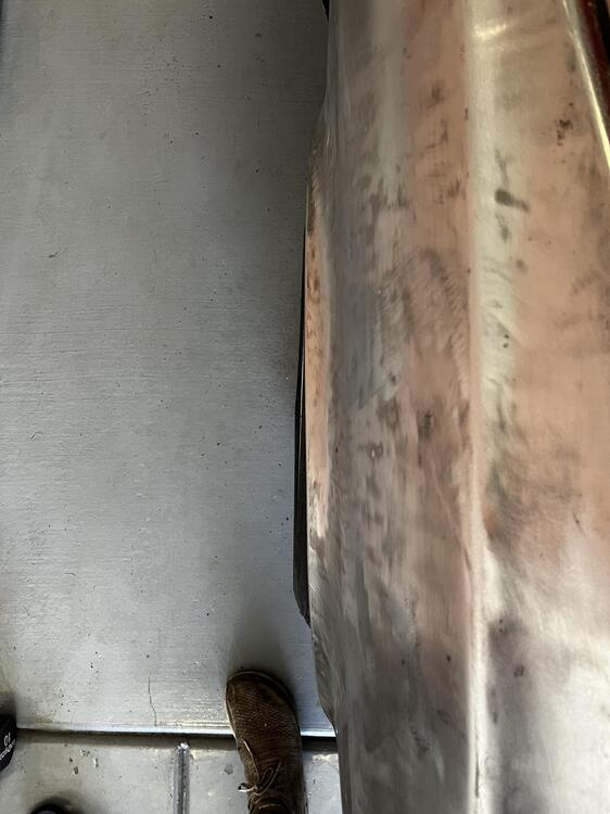
I got everything torqued down and took her for a spin after a couple months of sitting around! Apart from some small annoyances like my steering wheel off center (fixed after the drive) the test drive went well. I have some small steering wheel vibration but I’m not worrying about this with the old wheel and tire combo that’s on the car right now. I am betting it is just an out of balance wheel. When I came home I did notice that my passenger rear wheel has some toe in. As these done have toe adjustment, something isn’t right. passenger side: driver side: I took off the wheel for any noticeable mishaps. Nothing looks out of place and bushings appear to be seated correctly. I checked for any loose bolts or nuts in case I missed my first round of torquing. Perhaps there’s a sequence I missed? I then measured the two control arms and both were very nearly identical. I also measured my hub to the back plate and I could tell it was off in the correct direction by about 1/16”. Although I’m not sure this measurement reference point is most accurate to use? I’m thinking the old sloppy bushings hid this well and putting in new poly bushings shed some light to the issue. I’ll need to investigate more but it’s a bummer after putting in all that work!

-
Same issue here during my install. The strut rod would spin as soon as any meaningful amount of torque was applied to the top nut. I ended up using a make shift strap wrench to get it tightened down more, but definitely not to the Koni specs still. I believe you can buy a socket with a cutout that will let you slide in a wrench to hold the strut...but who has time for that! 😂
-
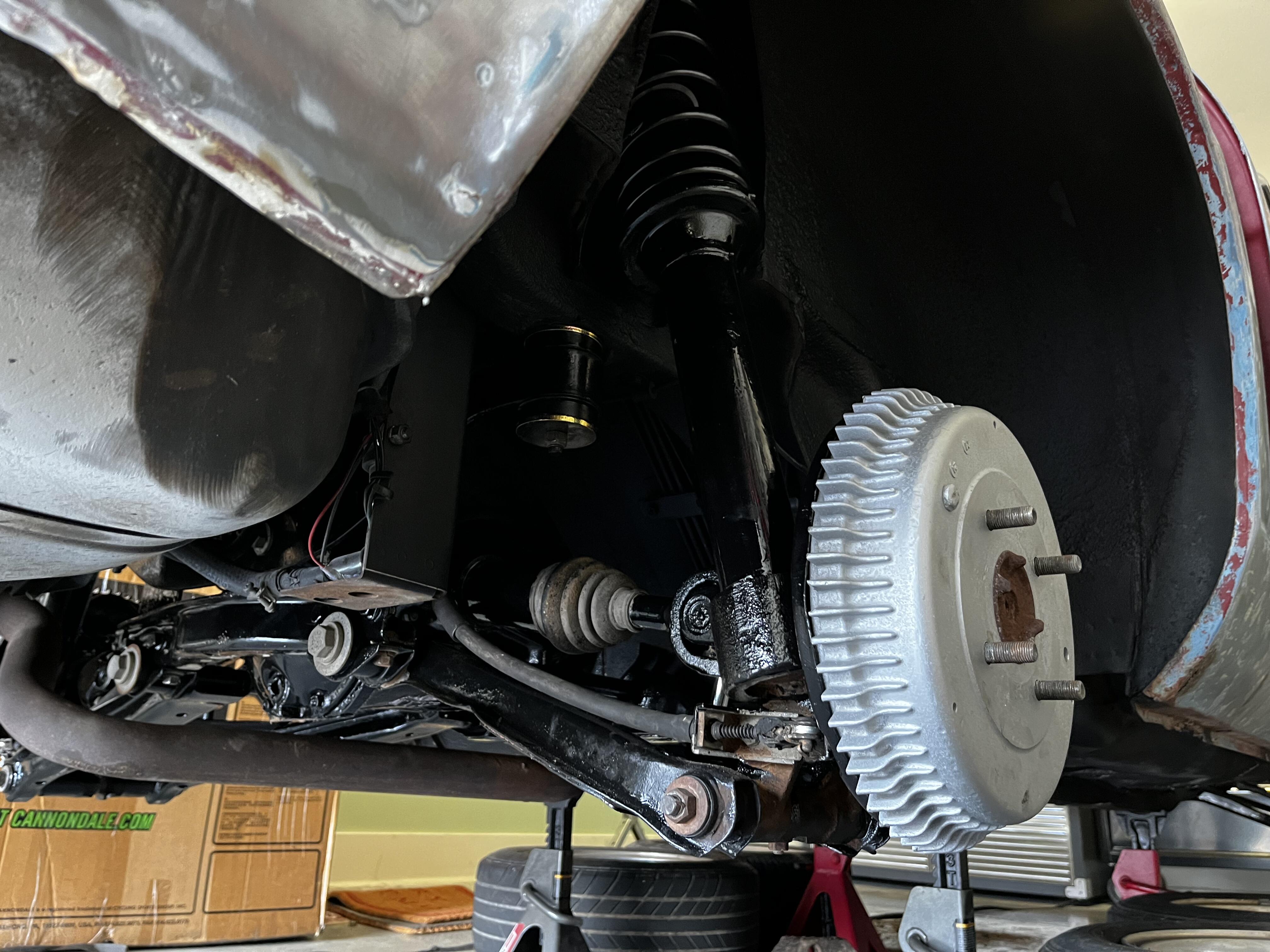
I was able to wrap up installing all the remaining suspension bits! Definitely not a fun job alone 😅 aligning the diff, lifting the strut assemblies, and that damn sway bar! Overall it went in smooth with only two hiccups. First being I installed the passenger side control arm upside my first time around. Second was the spindle pin does have a direction! I must’ve guessed correctly on the passenger side because when I did the driver side I noticed the locking pin wouldn’t line up. Needless to say, I think the spindle pin curse struck me on install since I didn’t pay my dues during removal. I still have some finishing touches before I can take a spin. Bleed the brakes, adjust emergency brake, torque bushings, adjust toe and camber. For those that have tightened the bushing bolts without a lift, any tips on reaching all the bolts with the car on the ground? I’m looking around to see if any friends or family have some ramps I can drive up as that was my first thought.


-
Gorgeous!!! Love the ride height as well. Where are you in terms of stiffness on the Konis? i.e. how many turns out?
-
No I dont think a camber kit is needed. I only went that route since all of my isolator bushings were shot and it was the same price to get the camber kit as oem replacements. So the added adjustability is nice to have!
-
I can’t wait to try them out! I finished painting all the parts and removing the bushings. I’ve started to reinstall the front end and making progress but it’s definitely slower than removal!

-
-
I have read this too. The aftermarket options don’t have nearly as large an opening as the OEM variant. I’m running a 280 radiator, two electric fans, and a full shroud. Inside is some distilled water with water wetter. No issues since I added the shroud!
-
That’s sick! I’m jealous of the shirt 🙂
-
Another side project I've been working on is creating a platform to sell some of the parts I have made during this build. Feel free to check it out: Hadashigarage.com Mods, please remove if not allowed.
-
Looks great. Those half shafts came out awesome. Did you install new boots as well?
-
Awesome, thank you!
-
When buying the TechnoVersions mount, is there a reason not to use the GM style mount? Seems like it simplifies the design and easier install. Perhaps increased NVH since its always in contact with the bushing?
-
Thank you both. I’m sure I can fab up a replacement!
-
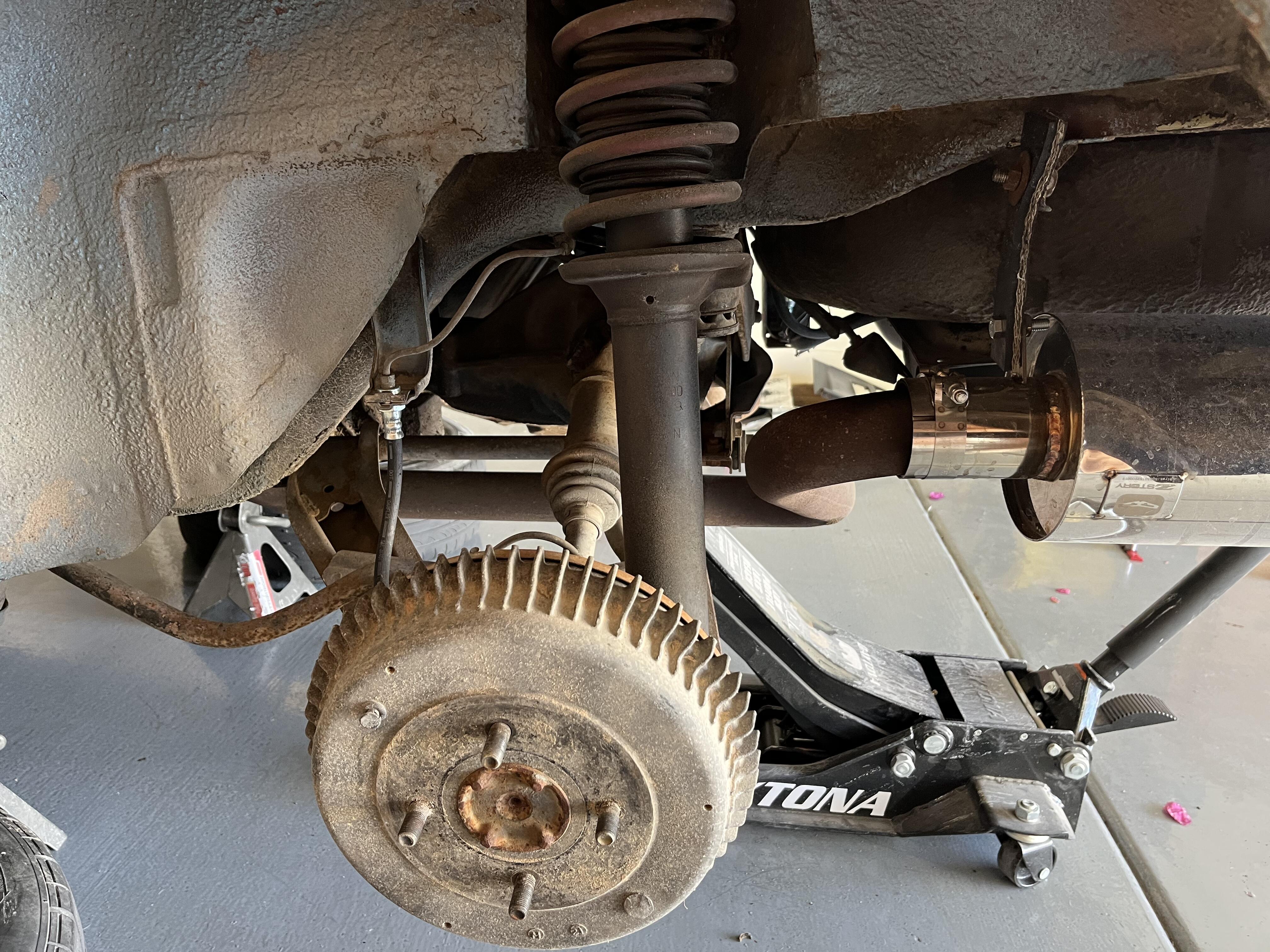
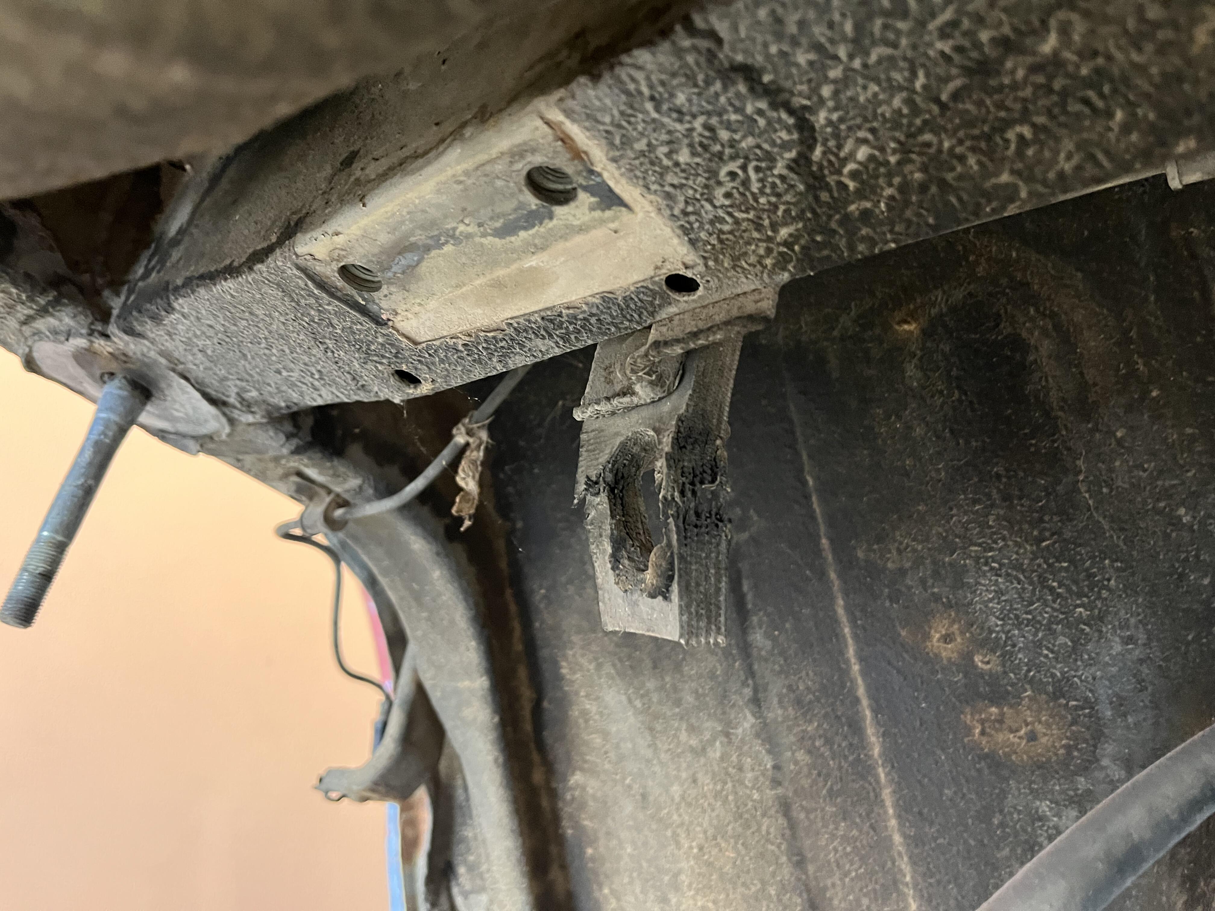
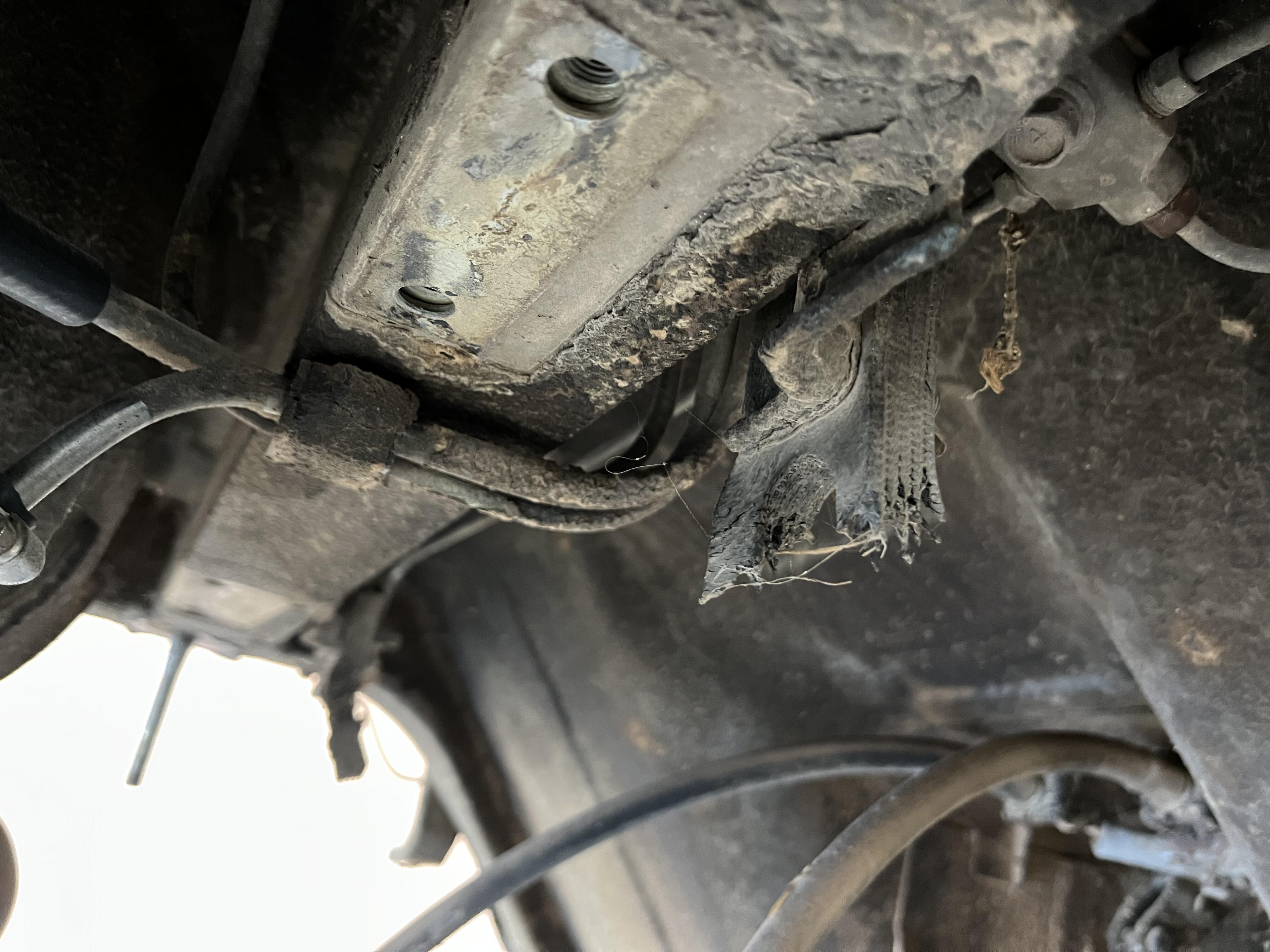
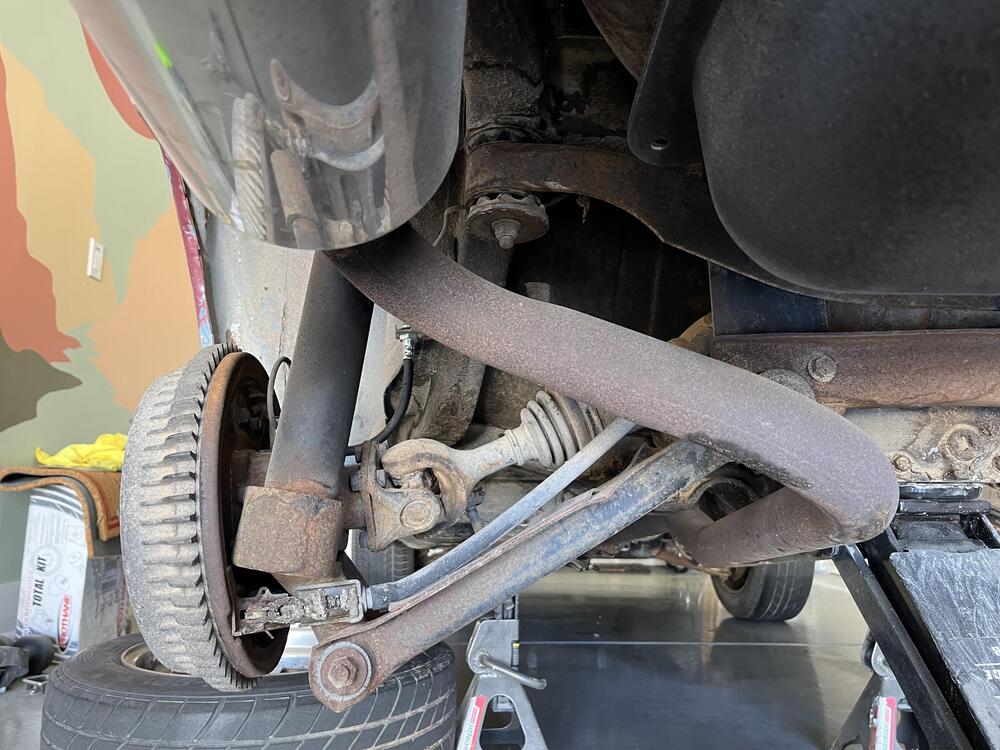
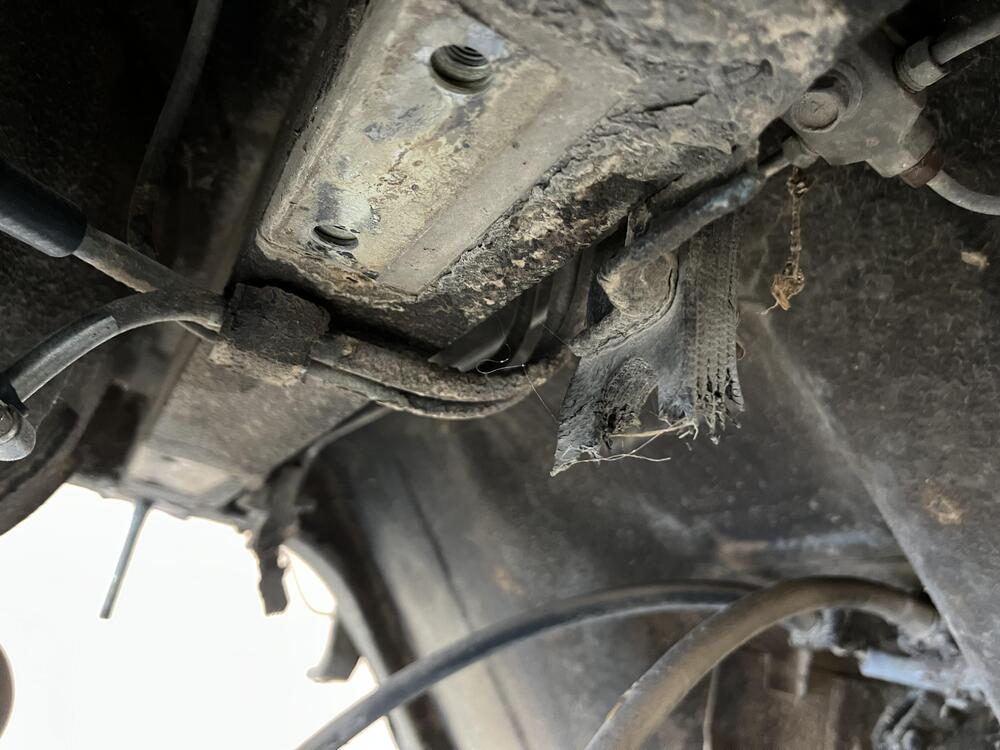
Today I spent the afternoon tackling the rear suspension. I’ve been dreading this since I first started my restoration. The spindle pin horror stories prevented me from doing suspension before the engine but we are finally here. I started off by ordering a set of eibach springs and Koni yellow struts. Topped off with a poly bushing kit, urethane bump stops, and MSA’s street camber strut isolators. All four of mine are toast and it is the same price as going with an oem replacement. Here’s what we’re working with. Luckily being and Arizona car, there’s little rust. Don’t worry, the exhaust is not welded up and just there until I can get it to the shop 🙂 Thanks to @Av8ferg for the tips in his build log on how to remove the rear end, everything went super smooth. I had the entire assembly out in just about two hours. My diff strap was still in one piece but brittle as hell so I’m glad to go with the technoversions diff mount. I did notice these two straps that are torn, can anyone let me know what these were for? I originally thought it was an exhaust hanger but there is one on both sides and they’re too short for a hanger. I was going to leave this as is for now. I didn’t want to dig into the spindle pins until the weekend in case things went south. I told myself, okay let’s undo the locking pin only. But it my surprise they came out without a fight. With the spindle pins staring me down ready to fight…I gave in and grabbed my breaker bar. Each pin had one nut that was fairly tough to release and then one that was nice and smooth. I imagine this is due to the direction it was facing on the car. I didn’t have a sledge hammer handy or a puller but I grabbed a standard hammer and started to give it hell. Within 3 blows it started to move! I couldn’t believe it. In the end, both pins came out without a fight. I think the Datsun gods gave me a lucky draw today…or maybe it’s just the Arizona car 😉 lots and lots of cleaning to do but the part I was dreading is passed. Knock on wood my bushings don’t put up a fight as revenge!


-
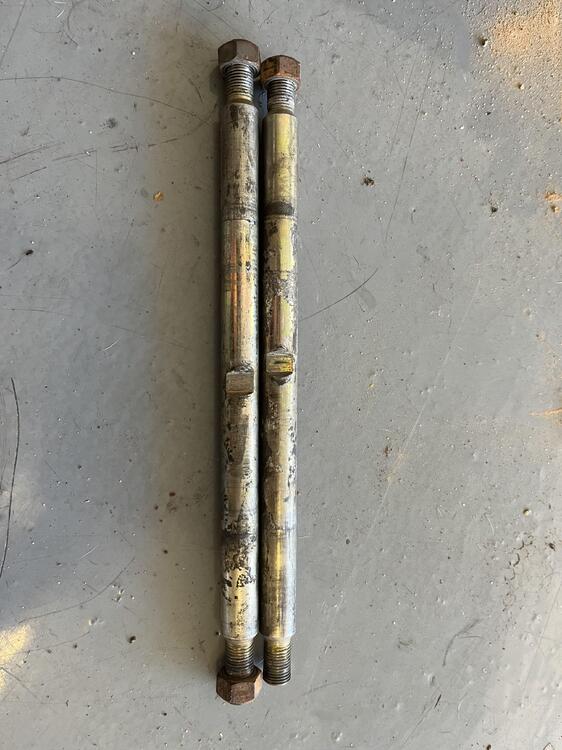
Here is what I found: Cut amounts 3/4" Definitely want a small gap, rather than compressing the bushing. Total length of the bushing after cut is about 31mm long. If you cut too much you can shim the bushing with washers. reference: Looks like what I was thinking of was the optional GM style mount that bolts to the differential. Oops!
-
I recall reading that you could measure the amount needed to cut off the car if you pulled the diff. I'll try to find that thread.