Barefootdan
Community Member
-
Joined
-
Last visited
Everything posted by Barefootdan
-
Haha touché! I just hate my paint work and its a good excuse to use some texture finish! Easier to get a consistent finish and it may just match the original plastic texture better as well.
-
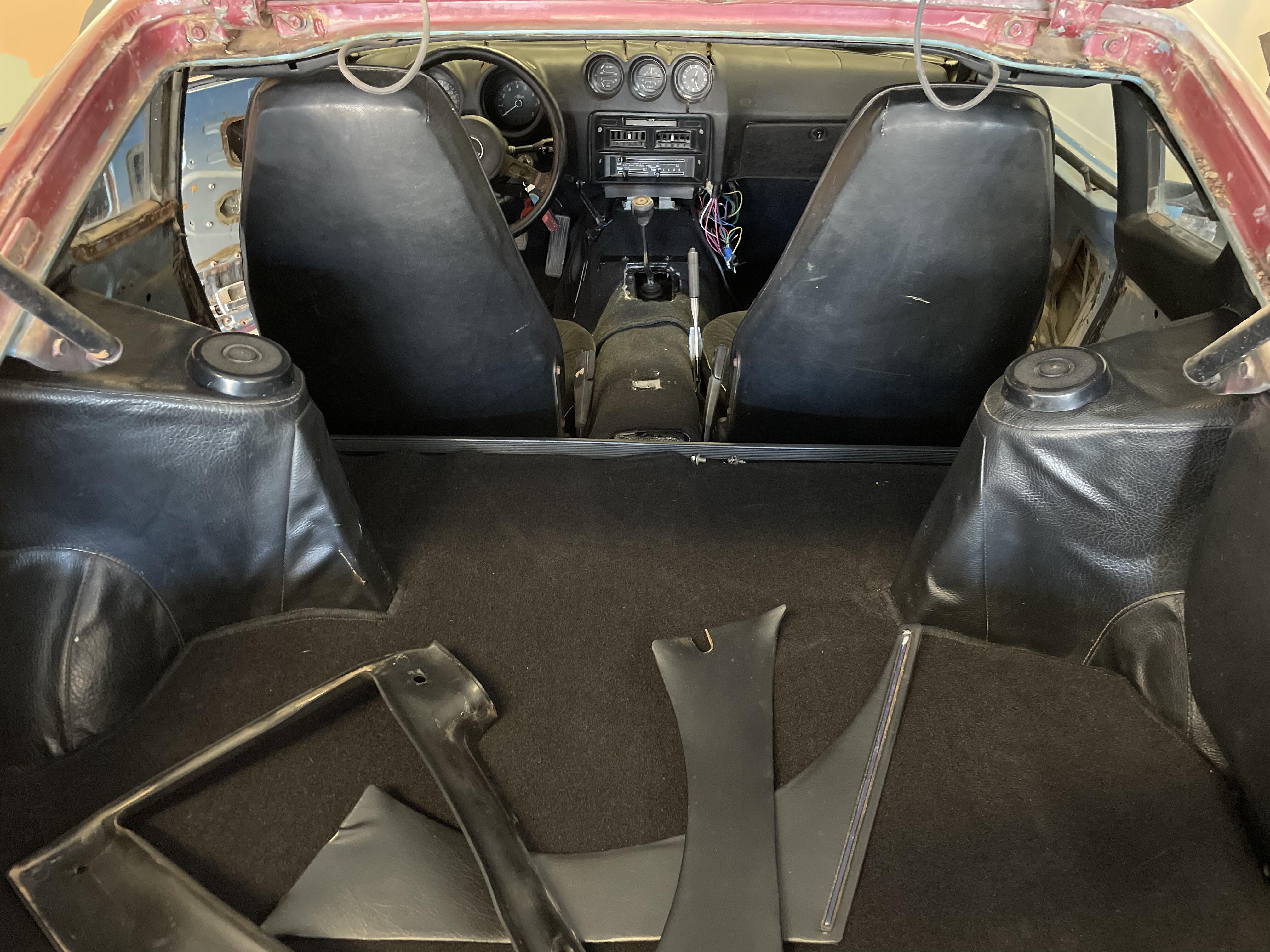
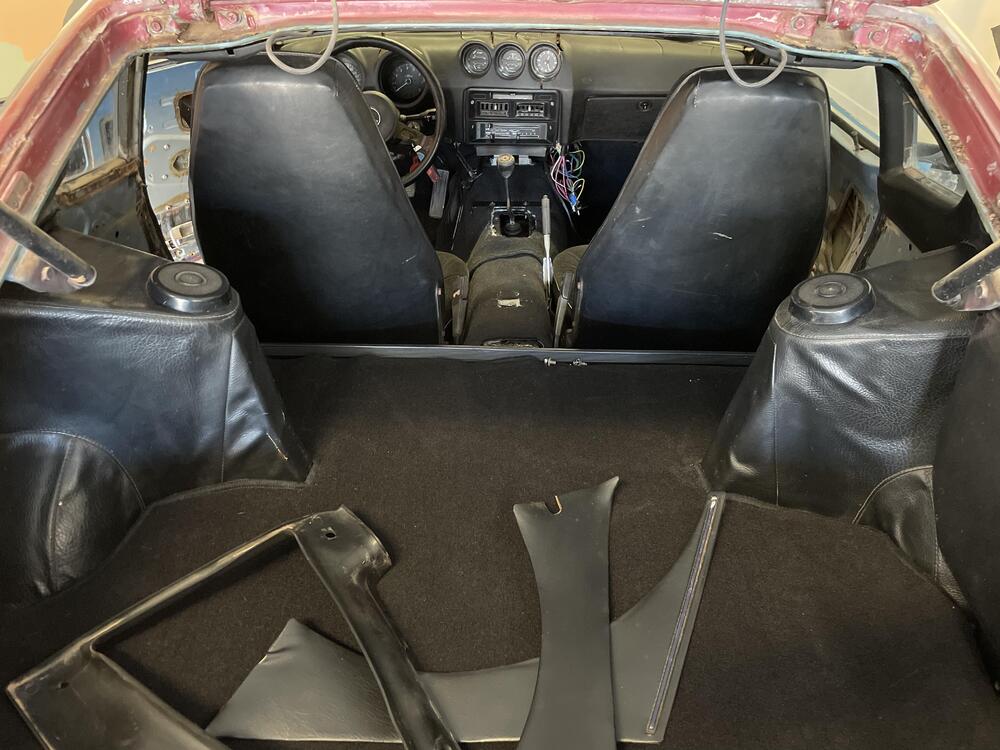
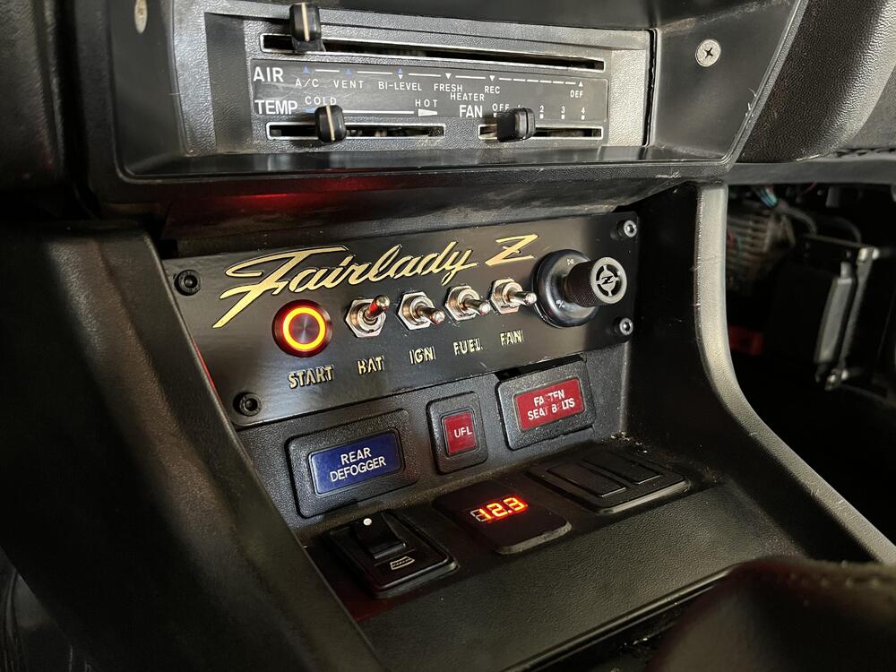
Got my jets from Dave and wow it’s already responding way better! I’ll have to wait a little longer before a street test but I’m super excited. In the mean time I have been putting the interior back in as I get the pieces. Carpet is done minus the inner scuff plates. I finally got around to completing my switch plate and radio housing. I used a laser cutting service to get some plates printed. I played around with some materials and loving the Brass. Kinda old school mixed with new. Shines nicely with the sunlight. Flipping my BAT switch to show the start light and volt meter. The Z knob on the right is my Bluetooth radio. I’m glad with how it all came out. I have multiple cuts of the plates so I’ll toy around with trying to get a texture finish for the black to blend in better. I’m thinking wrinkle coat maybe?

-
This is also what I used on my recent harness build. Worked awesome.
-
Me too 😞
-
Beautiful!
-
The Datsun runs once again! Still need to dial in my ignition timing, jetting, and fuel lines. But here is a sneak peak. I called Dave over at tuning4performance and had a nice chat about these mikunis. Ordered up a few sets of jets as I am running rich right now by the look of my plugs. A wideband O2 will be a nice addition in the future for fine tuning.
-
@Av8ferg You're going to be a master HVAC installer for this chassis by the time you're done! Don't panic yet 🙂
-
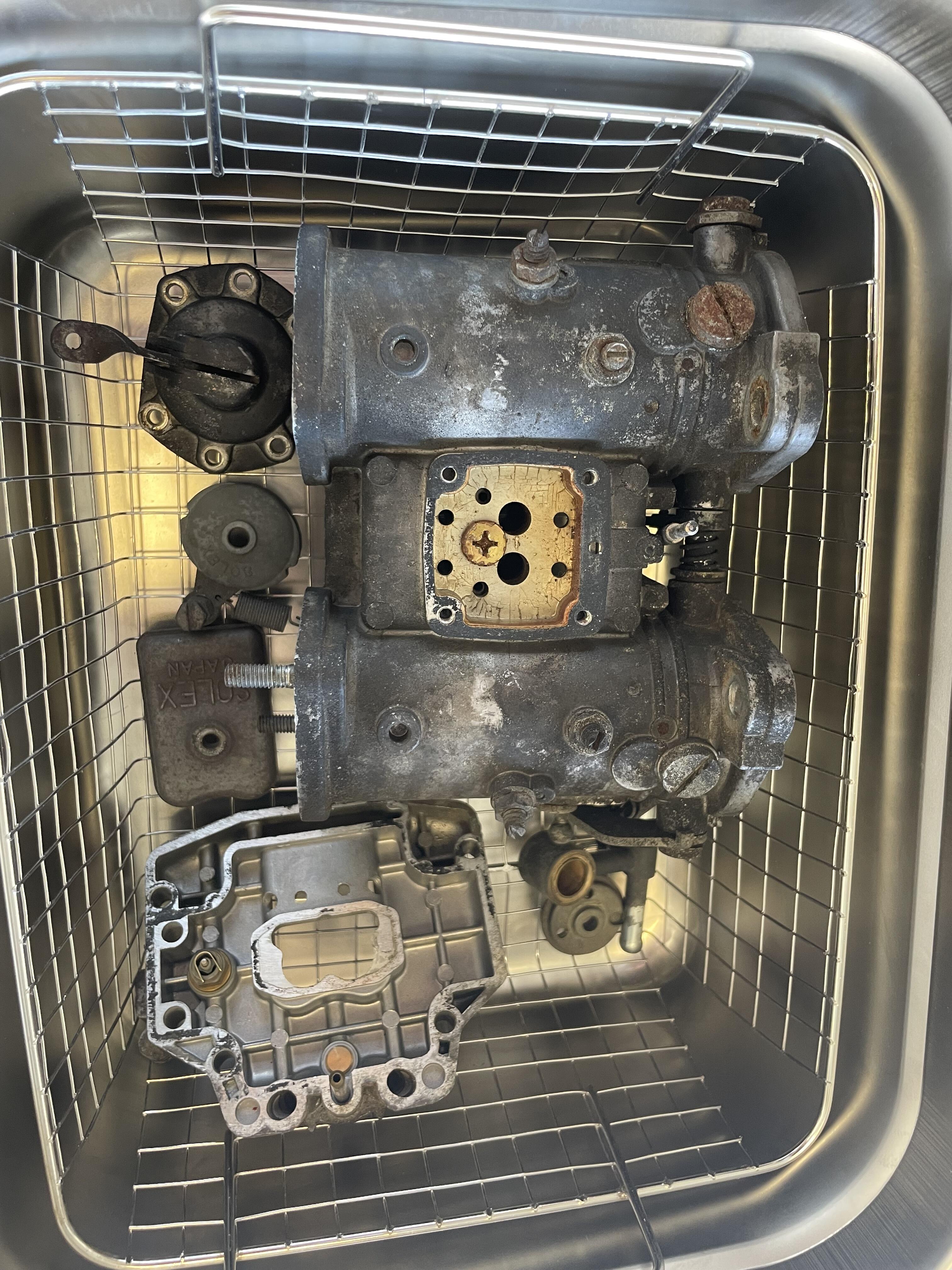
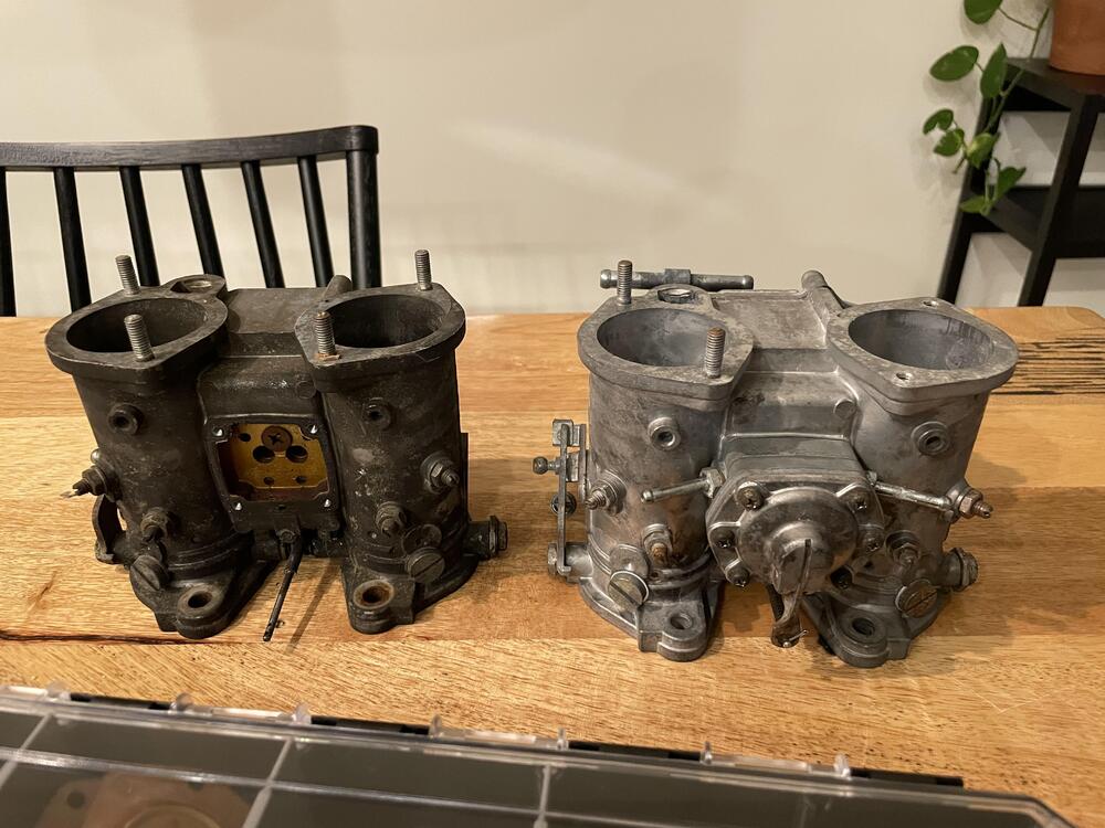
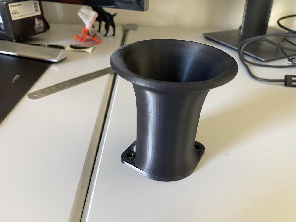
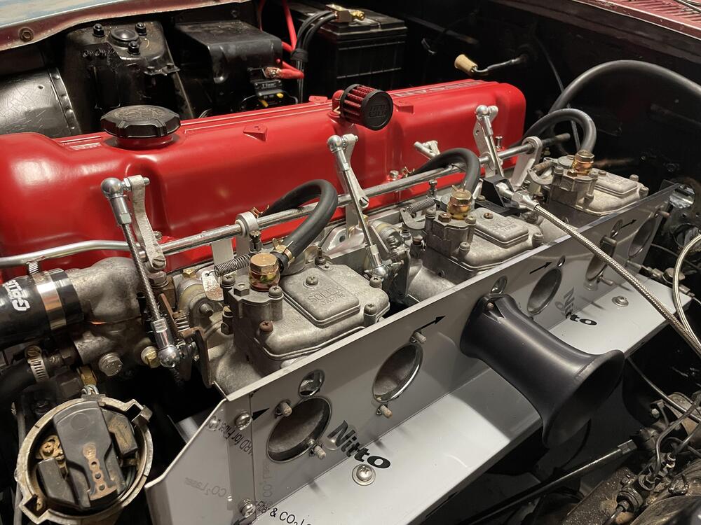
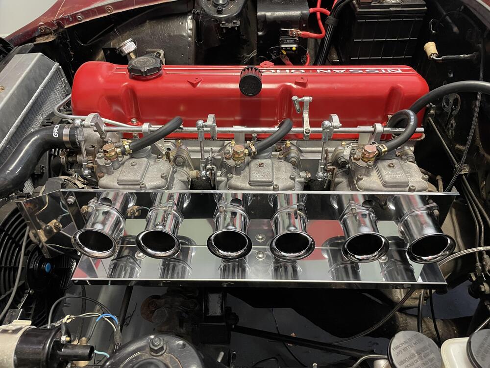
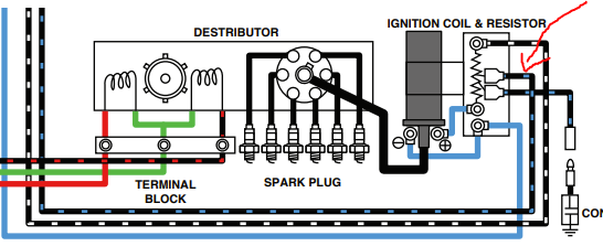
Now that the wiring is done, I was able to start working on cleaning up the Mikuni's. I purchased an ultrasonic cleaner large enough to fit the main body of the Mikuni and started to disassemble. They were pretty nasty and one even had some old gas that smelled horrible! I didn't take too many photos but here are a few: The first carb going in! I had enough room for cleaning almost an entirely disassembled carb in one shot with the 10 liter size. I used Simple Green Purple HD (safe on metals) mixed 1:3 to water. I set the temperature to 75 Celsius and ran it at 20 minute intervals. They came out great. Now perfect or new by any means, but for a "set and forget" clean, zero scrubbing, I'm very happy! If anyone is familiar with the PHH carbs, there is a check ball in the accelerator pump assembly that can get seized. 2 of my 3 were not moving when I started cleaning. They took almost a total of 2 hours of cleaning in the ultrasonic machine before they broke free. But it worked! I was worried as these are no longer in production. While I was cleaning, I finalized my velocity stack design and set my printer to work. I love how my first came out! This is ASA material which can withstand about 100C before deformation. It'll be interesting to see if the header wrap and heat shield is enough mitigation or not. The first mock up: But then I found a set of aluminum stacks for dirt cheap and I couldnt resist!! They look so good and I am glad I bought these. I still want to toy with the printed stacks as they are a more ideal length (100mm vs 55mm). Maybe once I find the perfect design via printing, I will order a machined set. I want to find angled banjo bolts. I dont like how I have to run excess line to prevent rubbing on my throttle linkage. These will work for initial tuning at least. Lastly, I was bored and printed a new knob for my Bluetooth receiver for the car. I modeled it after the side Z badging: I cant wait to hear these run but first I need to get my interior back in. The carpet has arrived and I am letting it air out in prep for the install. Lastly, I have one question for the wiring guru's. My ballast resistor is confusing to me. There is a Black/Blue wire that see signal only during cranking: Why is this? I did not notice this getting power only during cranking and supplied 12V during my test. The ballast became very hot after a a few moments (obviously because I wired wrong!) and I was not seeing spark. Disconnecting this wire gave me spark consistently. EDIT: I found out why it is getting so hot. I ran it to GROUND not 12V power. So now that makes sense at least. But I am still confused as why this sees 12V only during cranking and if it is still needed. Thanks all


-
I think it is this, on the left?
-
They are a MAJOR pain to get out of the holder. I think I was able to get 3 out before I resorted to cutting. There are 4 tabs that hold in each connector to the mount. I used small flat head screwdrivers to pry them open. @SteveJ I believe he is referring to the big white bulkhead mount for the wiring harness to dash, body, and fuse box. My google skills arent up to par to find a photo.
-
Thank you for confirming. The 11 feet needed makes it such an odd length for the 10ft and 20ft selections, hah!
-
Awesome work! Did you buy two different "mama bear" door seals originally to compare and end up running both? Just curious which of the two you prefer (if it matters).
-
Here you go @ETI4K! Each table is its own connector. I copied and pasted from my excel doc so hopefully theres no major formatting issues. A few of the colors didnt translate well but highlighting the cell makes it readable. I didnt mark what was removed though, although I'm sure its fairly easy to see 🙂 I did notice one connector where the colors of two cables look to be swapped (highlighted red) so I will double check that circuit. Lastly, I fused based on a quick google search, but I may be off in some cases. So far nothing is under fused as I havent had any pop. ECU 12 Pin ECU 12 Pin Checklist Working? PIN ECU SIDE ENGINE SIDE FUNCTION PIN ECU SIDE DASH SIDE FUNCTION Main power Yes 1 Green Orange Horn 1 Red Pink Switch Panel Power Starter Yes 2 Yellow Purple Reverse light power 2 Brown Brown Ignition Switch Fans Yes 3 Blue Blue Inspection light 3 White White Fuel Pump Switch Fuel Pump Yes 4 4 Blue Blue Fan Switch Ignition 5 Black Red Headlight negative 5 Light Green Light Green Low Beam Switch Low Beam Yes 6 Blue Blue Fan power 6 Blue Red Blue Red High Beam Switch High Beam Yes 7 Black/Blue Black/White Ignition 7 Blue White Blue White Cigarette Lighter/Map Lamp/Brake Switch Map Lamp Yes 8 Grey Grey Starter Solenoid 8 Green Green Black Horn Brake Lights Yes 9 Orange Pink High beam 9 Grey Grey Starter Switch Horn Yes 10 Brown Brown Headlight R 10 Blue Blue Water Oil Gauge Gauges Lights work 11 Light green Grey Headlight L 11 Red Green Turn signal switch power Reverse Light Yes 12 12 Green Green/Blue Running light switch power Parking Lights Yes Oil Pressure Tachometer Misc Connectors Gas Gauge 2 pin - Dash Engine Turn Signals Yes Pink White Main power Hazards N/A Purple Black Main relay Inspection Light 12V Radio N/A 2 Pin - Dash Engine Alternator Need internal regulator Yellow White Purple Thermostat Temp Green Green Temp Relay Power 1 Pin - Fuse Box Engine Black Black Ground Top Bottom Fuse Box 3 Pin - Body Dash Starter relay 10 amp High Beam Power 7.5 amp Switch panel 7.5 amp Green Red Green Red Turn Signal LH Gauge power 7.5 amp Cig lighter 10amp Green Black Green Black Turn Signal RH Fuel pump relay 15 amp Headlight Relay 7.5 amp Water gauge 5 amp Green Tellow Green Yellow Park Brake Light Reverse light 5 amp Fan relay 20 amp Ignition relay 10 amp Hazard 5 amp 4 Pin - Dash Engine Running light switch 10 amp Blue Light Blue Tach Signal Horn relay 5 amp Inspection light 3 amp Yellow Black Yellow Oil Pressure Turn signal switch 7.5 amp Green Black Blue Turn Signal RH Green Red Yellow Turn Signal LH 4 Pin - Dash Body Red Blue Red Blue Dimmer Yellow Yellow Gas Gauge Black Yellow Black Yellow Brake Switch Green White Green White Running lights 4 Pin - Fuse Box Engine Green Yellow Red Brake Switch Black Red Pink Reverse light XXX 12V Signal XXX Grey Alternator lamp Green White Orange Running lights 3 Pin - Fuse Box Body Blue Blue Hazard Power White Green Fuel Pump Power Black White Black Fuel Pump Ground 4 Pin - Dash Fuse Box Red White Light Green Headlight switch power Red Black Orange High Beam Black Blue Green Low beam Green Blue Gauge power edit: mobile site does not work well with this table! 😂 use your desktop if you want any readability
-
Absolutely @ETI4K! I will say that it is very basic and has many OEM circuits removed for simplicity. But I will definitely clean it up and share it here.
-
The wiring project is finally coming to a close. I’d argue that this took more work and effort than the engine rebuild and I would definitely rather rebuild an engine than another wiring harness 🙂 I envisioned that when I designed my own wiring harness digitally, it would make the whole process much faster, and in a way it did, but not how I imagined. What I learned by drawing out my own harness was more informational. I learned how everything worked, I became familiar with the OEM harness in both identification and functionality, and I may have gone a little crazy tracing black and white lines for hours on end. So going into this project I knew what I wanted to remove, what I wanted to replace, and what I wanted to add. I had the new diagram printed out in a 2x4ft poster for the garage and was ready to use this as my guide, but in all honesty, I probably looked at that poster 5 times in total. Once I started the actual wiring, it was far easier to do a combination of tracing OEM wires and using the OEM diagram. I still needed to find the correct length of each wire, so I needed the OEM harness with me anyways. This was also my first electrical dive into the car world, so I wanted to use the OEM diagram to ensure all circuits were correctly terminated. I think someone who is more confident in their wiring capabilities, and knows all lengths of wire (at least the minimum length needed) could use a self drafted diagram only. It just didn’t work for me. Now, enough boring talk, let's dive into what I used, how I used it, and what's next! Parts used: It was a bit of a pain sourcing electrical items with the current COVID supply chain issues. I knew I wanted to use 280 series fuse and relays for everything. I can't stand the look of regular sized relays, let alone 6 of them side-by-side. I also knew that I wanted to update all original relays and connectors to modern technology. Originally, I wanted to use a Bussman Distribution Block: This was my first choice since you can neatly organize your relays on the left, fuses on the right, and choose if you want busbars integrated or not. Unfortunately it was tough to find what I wanted in stock and I knew I would need a minimum of two to fit the amount of relays and power sources I needed. So I ended up using a GEP Distribution Block: The GEP block is similar in that it allows for 280 series terminals but allows for more flexibility in placement. The downside is there are no busbars so you will need external setups for your power in and ground.But it was available, so I can't complain! I picked up two generic busbars that had covers to hide most of the mess. It would have been so nice to just run one power wire though, via the Busmann Box. I paired this with 280 series relays, the simple 4 pin relay we all know, just smaller form factor. Do note, that while this is a 4 pin relay, it occupies a 2x3 portion of the distribution block. Still, I was able to fit all relays and all circuits in this 96 pin block with room to spare. Make sure the relays you order are for 12V and not 24V and rated for the amperage you need…I may have ordered up the wrong set initially. Next was my relay for the main power. I used an 85 amp weatherproof solenoid. Same function as the smaller ones above, just heavy duty as this is is handling all power to the car (minus the start motor): The circuit breaker I chose is okay. It feels cheap but is rated at 120 amps and is “waterproof”. We’ll see how long this lasts but I don't mind changing this out in the near future for something closer to the 85 amps of the solenoid. For now, it works and is a nice extra layer of safety: I was going back and forth on connectors for a while. Deutsch style, AMP style, Weatherpack style, there were so many choices and everyone has an opinion on this. Pick what you like, anything is better than 45 year old plastic at this point. I chose weatherpack because it was easy to source and the crimping tools did not cost me hundreds of dollars (I'm looking at you Deutsch….). Funny enough, I don’t think I would recommend weatherpack if you’re doing a full harness. Or at least not only weatherpack. I used the Metri-Pack (APTIV) 280 series. And while yes it worked just fine, I didn’t like how limiting this series was. With a 6 pin connector max that was a 1x6 setup, I constantly found myself wanting 8,10,12, even 14 pin connectors to clean up the look. Luckily they do have a Metri-Pack GT 280 series that is a much more modern design with connectors up to 16 pins. There are some amazing bulkhead connectors out there as well, but it wasn’t in the budget at the time. Don’t cheap out on the terminals and seals. I bought a pack off Amazon as I was short a few, but the metal is so much worse. The knock off connectors I found to be a decent copy but with slightly worse tolerances. I used these as a last resort. Lastly, the wires I used were a GXL rated wire. I picked up a pack of 18 gauge, 12 gauge, and 4 gauge for my battery leads. I would probably swap the 12 gauge for 14 gauge next time. So, we have all of the supplies, a plan, and LOTS of time to work…let's get started. I started by bringing the OEM harness to my “workshop”, aka my kitchen, and taped off connectors I knew I didn't need. Things like Air Condition, excess relays, emissions, interlock, etc. I then started with the longest wires and traced them with my new GXL wire for length. I labeled each wire to keep things documented. I only used 11 different colors and rarely had issues with micing up cables. I tried to logically use them so no two same colored wires went to a similar spot or into one connector. Once a connection was complete, I would tape the old connector as well to let me know I finished. Doing the tracing took me a full evening for the engine side. I then tackled the dash and body. My connectors here on the OEM harness weren't bad so I decided to keep the original setup and splice my two setups together. Looking back, this worked just fine for the body harness but I wasn't a fan of doing this for the dash. The dash wiring gave me more headaches than the engine bay and body harness combined. Anyways, once my harness was laid out, I wanted to toss it in the car to see if my lengths were accurate and to give me a visual aid if I missed any wires: Everything fit perfectly and erred on the long side which I was happy with. So I could start the terminating process! Does that make me The Terminator?! This took the most time and definitely was the most tedious. Each wire needs a weather seal and pin lined up in the crimper. It was also overwhelming on where to start. I have this huge mess of wires and was lost on “Do I start with the power side, or the accessory side?” I wanted to follow the flow of the current so I ended up with the power side. I mapped out my distribution block and just started one by one. It was easy to get lost in the wires but just do one circuit at a time. Each lead off the distribution block had about 10-12” of wire which would then terminate to a weatherpack connector. I would then match this with a connector at the start of my harness and connect the two once complete. I did not terminate the accessory side of the harness yet so I could trim the wire to the length needed once in the engine bay. About 15 connectors later I am ready to start testing this spaghetti, mama mia! I immediately ran into a couple issues that I would highly recommend people do differently! First, as soon as I layed the harness in the car, I saw my absolute abundance of connectors under the dash. Was it functional, absolutely. But it was just a disaster there and I bet driving down the road would sound like a toy bin with all the connectors bouncing into each other. So I ended up ordering a pack of 12 pin connectors that would consolidate my setup. I used a 12 pin for the distribution block to the engine bay, and another from the distribution block to the dash. I do have a few weatherpacks thrown in for the body harness for my 12 gauge wires. The other issue I had was with my distribution block location. I knew I wanted to use the original fuse box spot, but when I did my wiring, I didn’t have exact lengths for everything (Block to busbars, block to harness, etc). I would suggest people tackling this to make their mounting plate first, then start your terminating. I had to shorten everything after I made my plate, oops! Once we settled that, I could start running my main power. I ran 4 gauge wire from my battery to a 125 amp breaker. From there, we travel to the 85 amp solenoid. This is triggered by a master kill switch on my switch panel that always sees 12V (through a fuse). This will finally feed power to my distribution block. I didn’t want to hack up the original mounting plates so I used existing holes and I am satisfied with how it came out. I would prefer the breaker to be hidden but I can always move it in the future. So I have power now and the testing can begin. I started with simple circuits like my fan relay, starter relay, etc. I created a spreadsheet that lists all circuits and if they were functional yet. In my previous posts, you will see that I ran into a couple hiccups along the way but nothing major. I can't tell you how many times I wasted 20 minutes or so diagnosing a circuit when either the main harness wasn't even connected or my power switch was off! Too many things going on in my head and I lost track of what was done. I mean c'mon, this looks organized right? …right?! What a mess!! It looks worse now than when we started. But I promise it works! And I promise not to shove it up under the dash as is 😄 There are a few items left to still test, but I cant before the engine is hooked up to the new carburetors. Things like oil pressure, alternator, tachometer, etc. I feel confident enough now to start looming my harness and wow what a difference this makes. The harness now comes back out again to get a last review to make sure all of my splices are sealed and nothing is mangled up. In my spreadsheet, I updated all of my notes to match what color wire I used, where it is pinned, and when it sees power. This changed a couple times during my testing so I am glad I did this step last. I used this split loom in various sizes to wrap. It was very nice to use and allowed for T-offs very easily. This was also nice to use since I didn’t need to remove my connectors to wrap. Each end was also taped up with some fabric tape just to ensure nothing would shift around or unravel. I grabbed a firewall boot to help keep the elements out as well. Here is the final product, a fresh harness! I am so pleased with how this turned out. I hope this helps you guys with any wiring projects you run into. Feel free to ask questions about specifics like what pins I used, what tools, quantities, prices, etc. But this post is already mega long so I spared you the details 🙂 But now what? The carburetors are getting dismantled for the ultrasonic cleaner, and rebuild kits are ordered up. Once every circuit is finalized I will move my way to the interior, finally!
-
Wow! I will be sure to do the same. It didnt even cross my mind to change the fuse down
-
Thank you again @SteveJ. I ordered up the LED lights and wow what a difference this makes. I no longer have the flickering issue with my non-blinking lights and I bet my wires are much happier with the lower amp draw.
-
I’ve never thought about leaving them on actually! I rarely ever use high beams and if I do it’s mainly for signaling people. If I find I want to leave them on I could always go to a switch that swaps between two outputs 🙂 Thats right! I wasn’t sure what that spot was meant for.
-
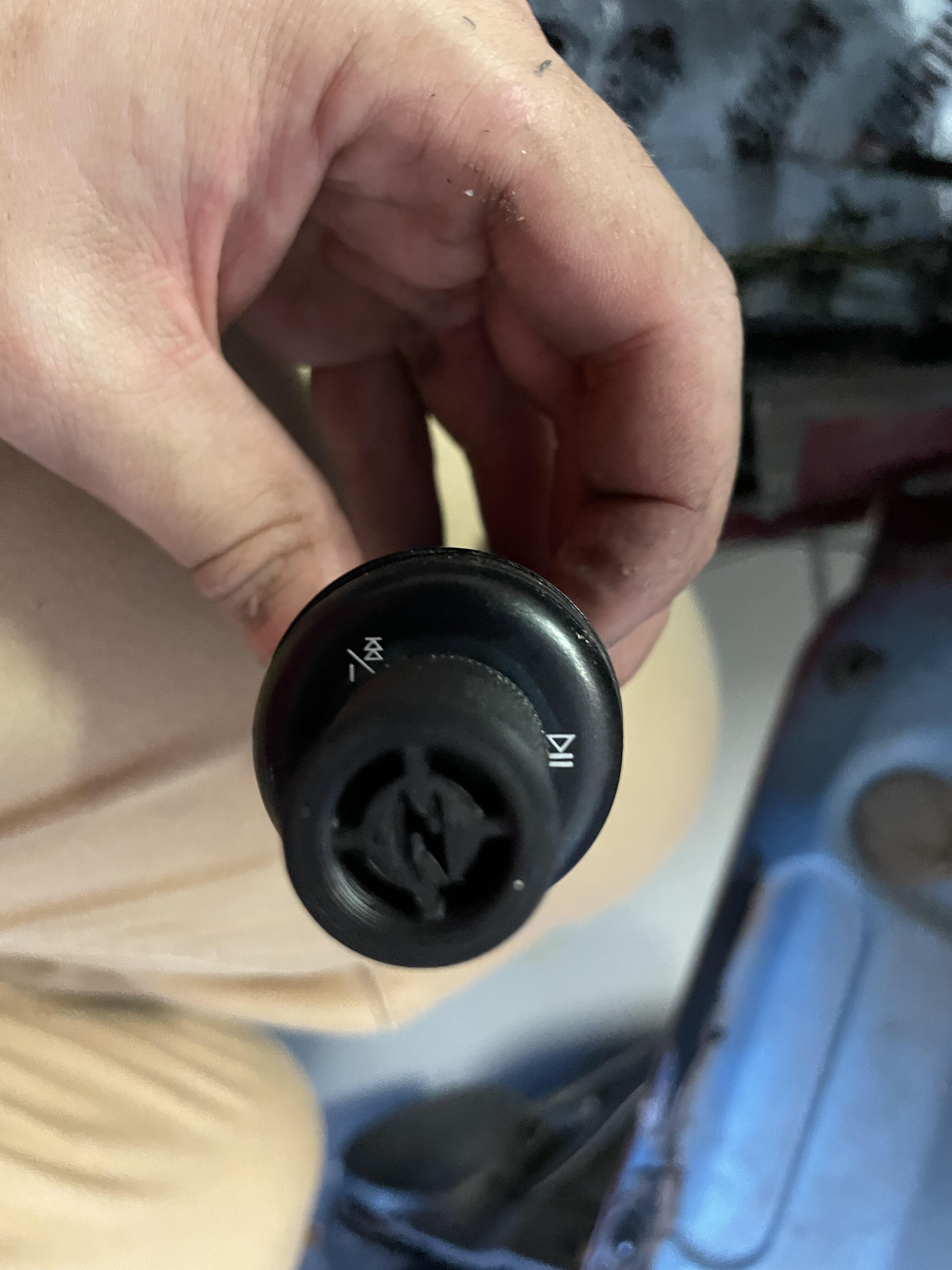
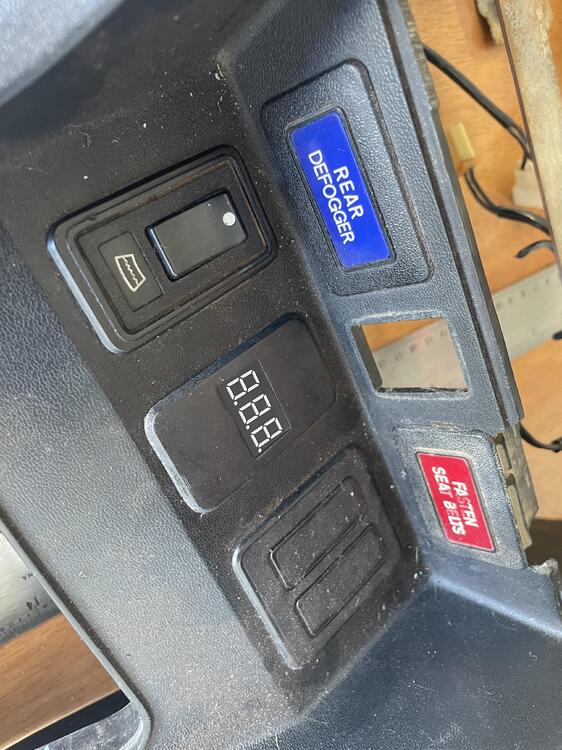
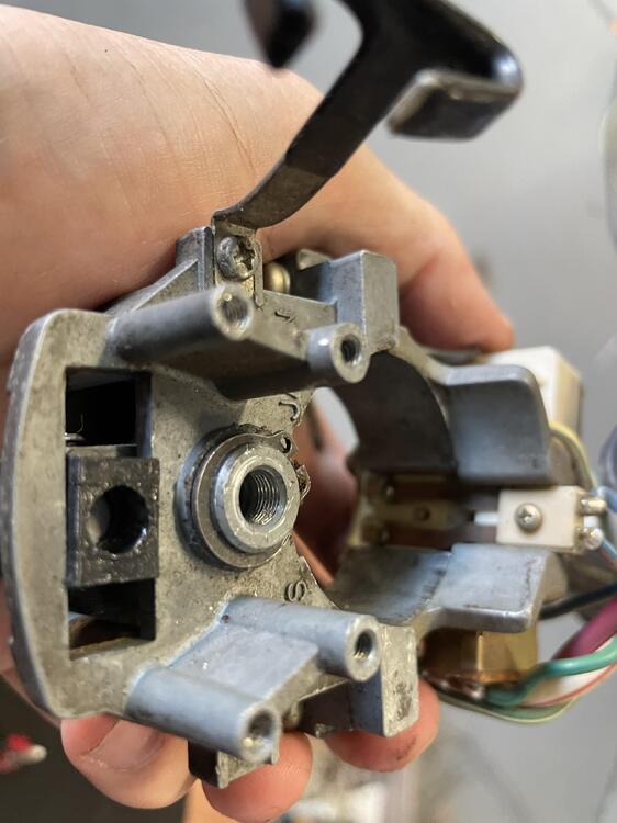
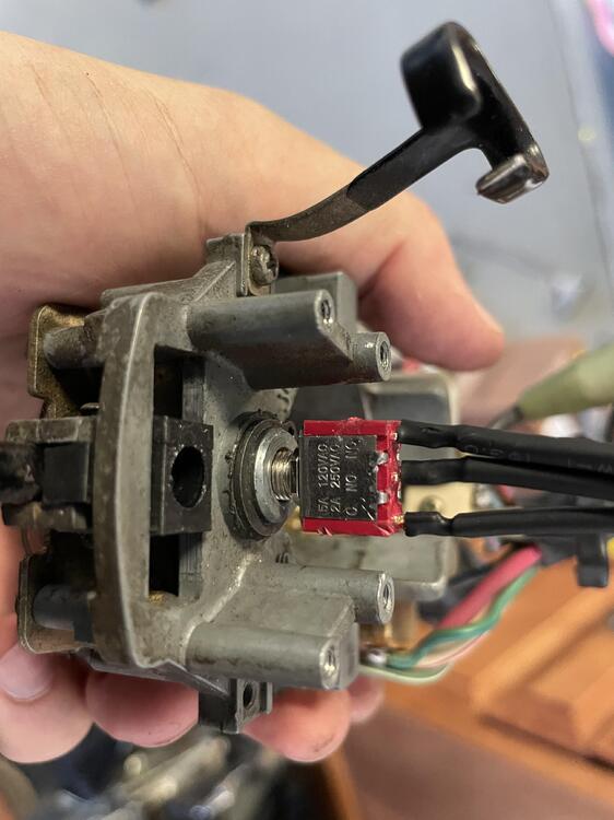
Ah, I remember now why I didnt use the original stalks for headlights! The high beam switch is baked into the turn signals. Pull the lever to activate. I took a wild guess at a 3 way switch and to my amazement, it fits perfectly. I needed power to 1 pole of the switch and always be on for a second pole (Low Beams) and when pressed, it would swap to a third pole (High Beams). The trick was I needed the switch to be a momentary one as well. So that when I release, it went back to my low beams and did swap between the two outputs for each press. This switch accomplished exactly what I needed and the size needed no modifications either: https://www.amazon.com/gp/product/B079D923V9/ref=ppx_yo_dt_b_asin_title_o05_s00?ie=UTF8&psc=1 Just be careful when you solder this little bugger. I put too much heat at first and I think I ruined the contacts. With my wires soldered up, I could work with mounting. I originally planned to 3d print a mount similar to my turn signal switch. But when aligning everything up I was shocked at how well the threads matched the rear of the stalk. A quick tap: and viola! There is a satisfying click when pulled as well so you know when it is on or off. Not mushy at all. I still may 3d print a brace since I have the provisions for a mount and its a super simple shape. But for now I am not worried about this coming loose. Now my original stalk works again for turn signals, headlights, and high beams! Lastly, a quick model for my center console. I was missing a plate next to my rear defogger and created an adapter for a volt meter. Nice to have since my wiring is all new and I can monitor it at all times. If you recall, I took out my shunt so I wont be using the amp meter. I may look into adding a small USB port here as well, but I dont want to get too cluttered up. Sorry for the dusty console 🙂 I am wrapping up the wiring job and only need a few small pieces left before I can do the final sleeving. My interior is an absolute disaster with wiring bits everywhere. Organized chaos, I swear!
-
Could you find a molder 90 bend and snug it on to the core deep enough to fit? I imagine you can gain a couple mm of clearance by sticking the core “into” the bend rather than leaving it in the straight portion. It may inhibit flow a little but I don’t see it being a huge deal? In lieu of a flare tool, do you have access to soldering equipment like used for plumbing? Last thought would be something like a PETG fitting. I know they are used in computer for water cooling and no flares are needed, allowing you to trim down your pipe as needed
-
Wow, thank you again! This is perfect! You just made me a happy man and my wife…well let’s not tell her about this extra upgrade! 😉
-
That’s a good option to use LED’s. The rears look like an easy swap and the fronts just need a new housing that can take the H4 bulb. Hmmmmm I may just add that to the list! I don’t have a reason to specifically not use the stock stalk. I was planning to just remove it entirely since I wasn’t using the other functions of that stalk. But now it seems like the better option to just keep it.
-
Thanks @SteveJ! That leads me to my next question. I want the parking lights to be on anytime my headlights are on. Is parking light the correct term here? I am referring to the low light filament in my turn signals and taillights your mentioned. Since I have a toggle switch for my headlights, I initially thought I could route a wire from the output of my relay to turn these on. But i am thinking the this will backfeed between the high and low beams and both will be turned on. My next thought was to use a rectifying diode but my research is leading me to voltage drops (not something I want for my lights!). Is my only choice to place an additional, completely separate, switch to run these light? Similar to the OEM setup. Sorry for all of the electrical questions lately. I am so close to finishing this harness 🙂 I appreciate all the help.
-
Looks like a dead bulb. Two new ones on order! Next, quick question on the operation of the parking lights. How do the front operate with the turn signals? Right now I have both (turn signals in my grill) on (when my headlights are on), then when I use my turn signal, the appropriate side blinks while the other stays on. Is this correct or should the non blinking side be switched off during my turn signal? I question this because it kind of looks like the non-blinking side has some power draw and ever so slightly blinks as well (Brighter when the blinking side is off, Dimmer when on). I am not sure if this is because the car is not running and my poor battery has been powering my project for a couple months now without charge 🙂
-
Thanks @Zed Head! "At whichever beam", I meant that if high beam is on, I should see 12v through the high beam wire, low beam on would mean 12v through the low beam wire. Never should I see current in both wires simultaneously. Being that I rewired my entire harness, I am not using the OEM style setup. Rather, I am constantly grounded (not powered) then turn on or off the high/low beam via a relay and power. It makes sense that there could be backfeed across the filament. I'll go check out the resistance and scavenge for some test lights too. I think my circuit is okay, but the bulbs are throwing me off. The joys of doing a wiring harness before testing every circuit prior to removal 🙂