Barefootdan
Free Member
-
Joined
-
Last visited
Everything posted by Barefootdan
-
 The wiring saga continues. I started to test each circuit and working my way through one by one. I am trying to diagnose a headlight issue that is stumping me. When the switch for low beams are on, both lights illuminate nice and bright. When my switch is on for high beam, only my left light is on (dimmer than low beams) and my right light is VERY dim. I am disregarding the fact that high beams are lower than my low beams for now since that is an easy fix on my switch. I started to trace my wires and check voltages at each connection. With low beams on, both plugs see just under 12V at the low beam and 0V at the high beam. With high beams on, my left light sees 12V at the high beam wire and 0V at the low beam. The weird part is, with the left light plugged in, and I check the right light, I see 12V at the high beam and 4V at the low beam. I then proceeded to unplug both lights and check continuity as something must be shorting. Right light sees continuity between the high beam and ground. Also continuity between low beam and ground. No continuity between low and high beam wires. The story is different for the left bulb. Continuity between all 3 wires and combinations. Which side is correct? I want to say the right side is correct but it is not illuminating bright enough (could be a bad bulb as well). My assumption is that I should ONLY see 12V at whichever beam (high/low) is on, never both.
 -
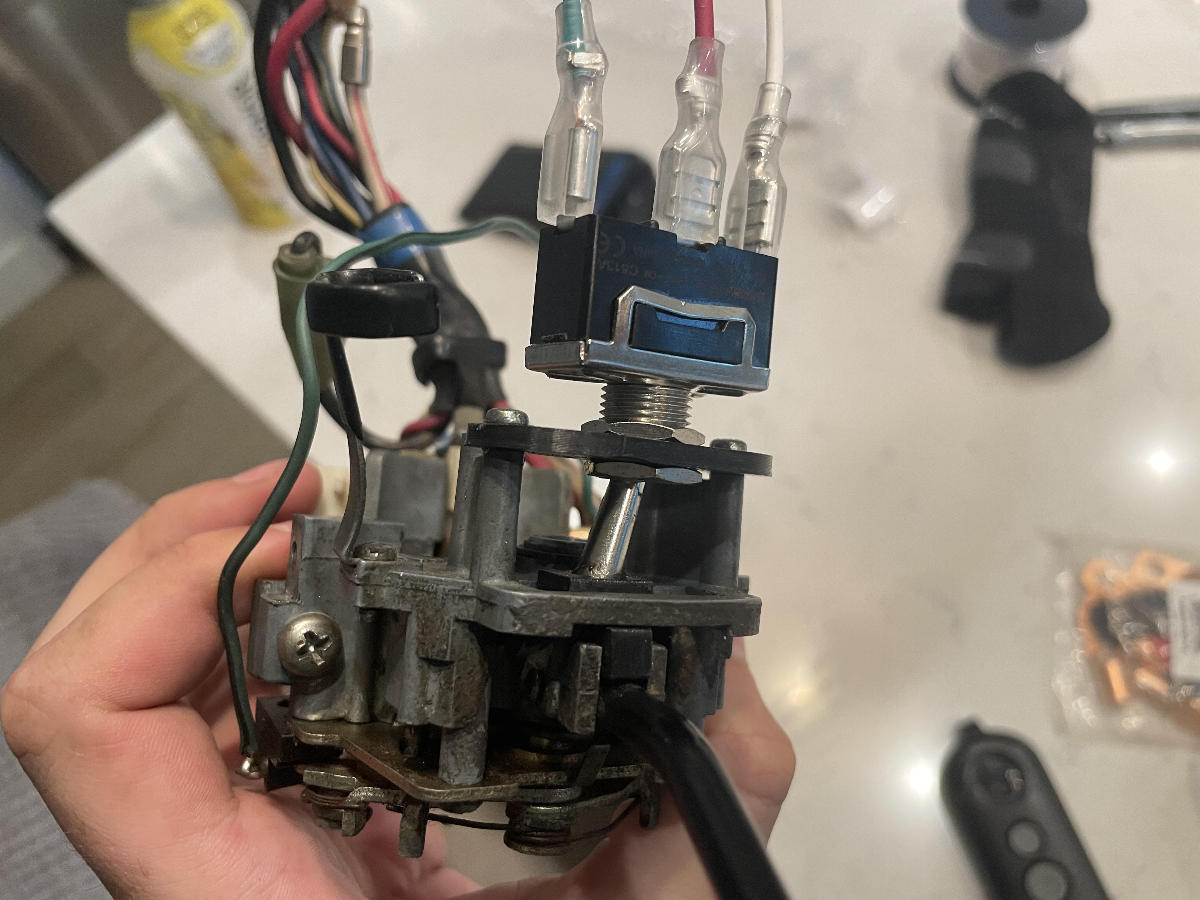
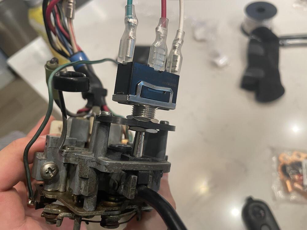
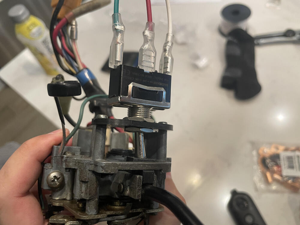
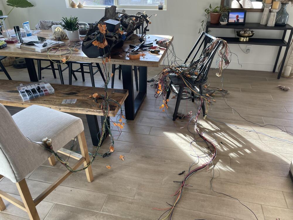
Take whatever time estimate you have for a wiring job and double it 🙂 So many lessons learned and I cant wait to share them all with you when I am finished. But for now I was working on fixing my turn signal stalk. The PCB board was so brittle that when I disassembled to clean the contacts, it was just falling apart. I was a bit upset that it came apart and I started to look into replacements. I really wanted to keep the OEM stalk and not go aftermarket. Everything was fairly pricey though, so I looked into fixing myself. I found this thread on HybridZ where a toggle switch accomplishes the same function of the OEM switch. A quick print for a bracket and new slider and boom, we're back in business! The switch in the Off position: Then each direction works flawlessly. It retains the nice CLICK as well.

-
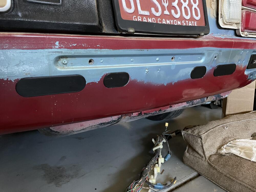
Thanks @Av8ferg! I will totally print up a set of the bumper plates. One thing I am wondering is, are all bumper cut outs the same size? I only have my '75 to measure. If you get a chance, can you let me know the dimensions of one larger and one of the smaller cutouts? Just want to make sure before I send something that doesnt fit 🙂
-
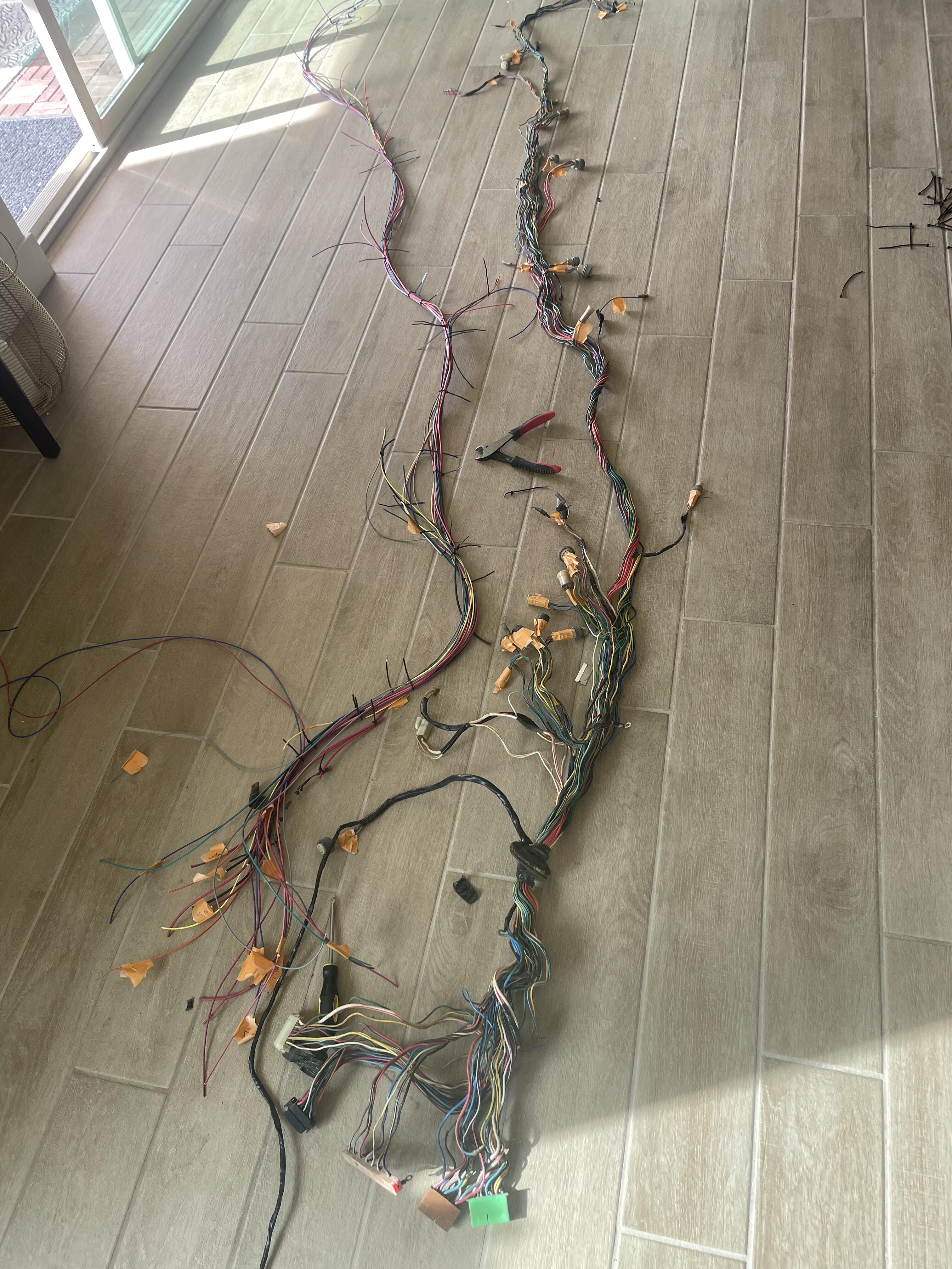
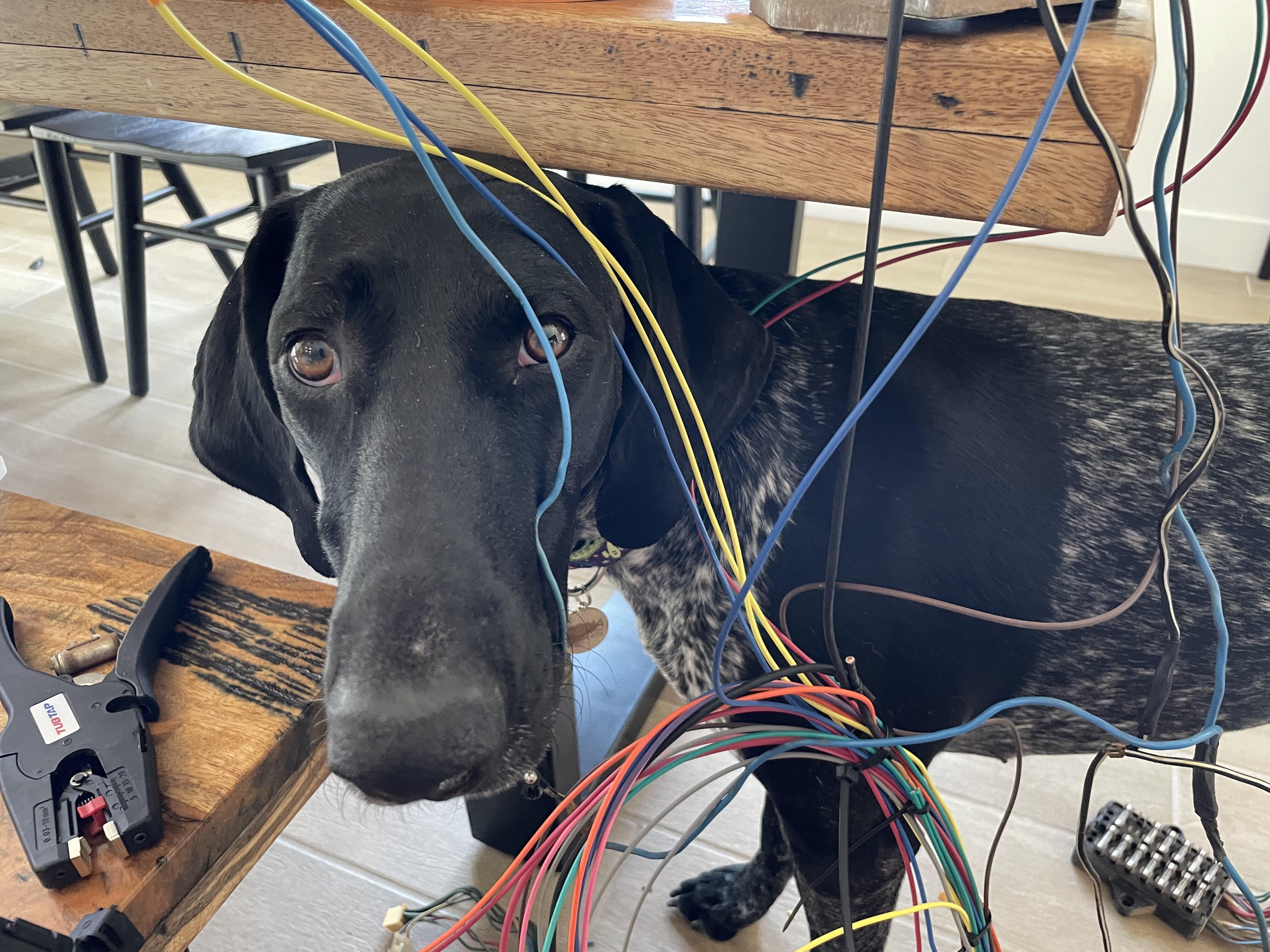
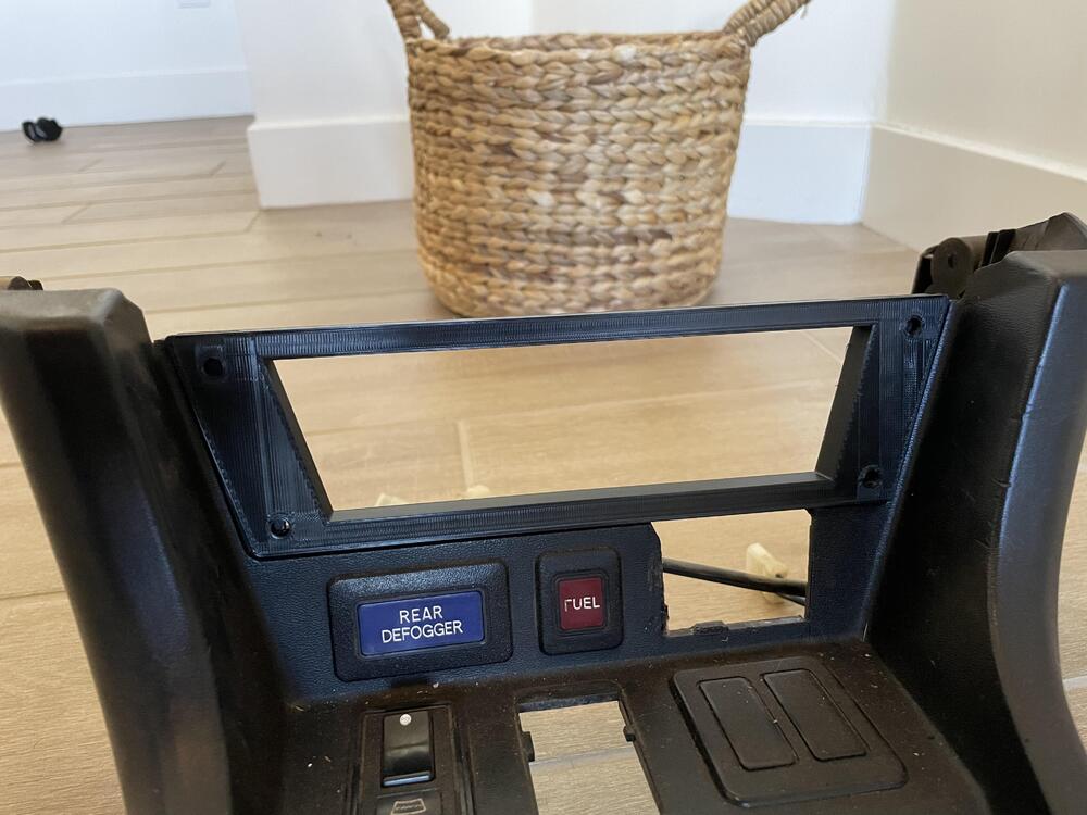
A few updates since last month. I’ve been able to find the studs needed to mount the mikuni manifold. Cleaned and painted it as well. Can’t wait to clean up the carbs next. I’ve been playing around a lot with the 3D printer. I created a faceplate adapter for my switch panel. Slides into my center console and I will be able to screw on the actual switch panel to this adapter via the four screw holes. Looking at original center consoles online, it looks like mine was hacked up for an aftermarket radio at one point so it was missing the upper material. This new adapter should add back in some rigidity. I also toyed around with some filler plates for the rear bumper. I know the proper way is to weld in blanks, but this was just a fun side project 🙂 they clip in and are fit very nicely! And then the big project of wiring has started. The engine bay is getting a full new harness, then I am creating adapters to plug into the dash and body harness. Originally I wanted to redo the full body harness as well but all of the connectors inside were fine. Laying out the harness side by side for lengths. Organized chaos! Luckily, my wife is out of town this week so I’m taking advantage of making the dining room a workshop for a bit. Test fitting in the bay before I start adding plugs! So satisfying to see it come together. My little helper! Im about 80% done with the fuse box side of the harness. A few small fused items left to run and then I can start working on connecting the engine bay side. During this I deviated from my original schematics so I will be needing to update that for future reference. I removed my shunt, externally regulated alternator, and all original relays/flashers. I won’t be running my amp meter, instead going for a volt meter. All relays are now modern bosch style, albeit the micro 280 series size to fit within my distribution block. I have a main 125amp circuit breaker in place, continuous duty relay as a main power trigger, and all new weather pack connectors with GXL wire. There a few circuits I’m slightly confused on so I’ll need to finish those up in car to trace all of my leads accordingly. Surprisingly I barely used my schematic I made. I used the OEM wiring diagram more often. Maybe I need to trust myself more 😉


-
@Av8ferg I won’t be using any of my oem hvac system besides the control panel. I can send you some photos of what I have in hopes it can help. I’m not sure how operational it is since I never tried to use it and it sat for 20 years. Let me know 👍
-
I took mine out about a month ago, I can snap some photos if you need any. But pretty much, remove all the screws 🙂 there were a couple screws holding it to the firewall (I believe on the driver side) that I missed for the longest time. I pulled the core and HVAC controls all together. You’re on the right path by removing the blower first.
-
Leaking heater core perhaps?
-
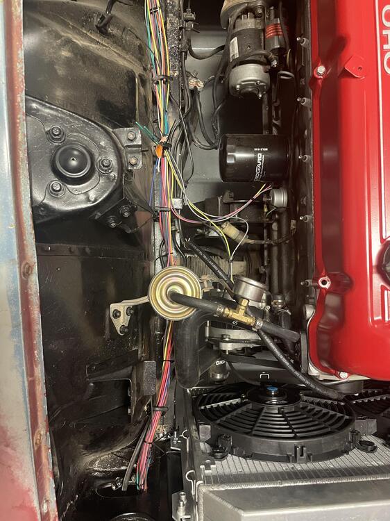
My suggestion would be to remove the line that goes from the back of your block to the front and plug both ends. It would mimic the OEM heater core when you’re not running heat in the car. Hopefully improving your cooling issue?
-
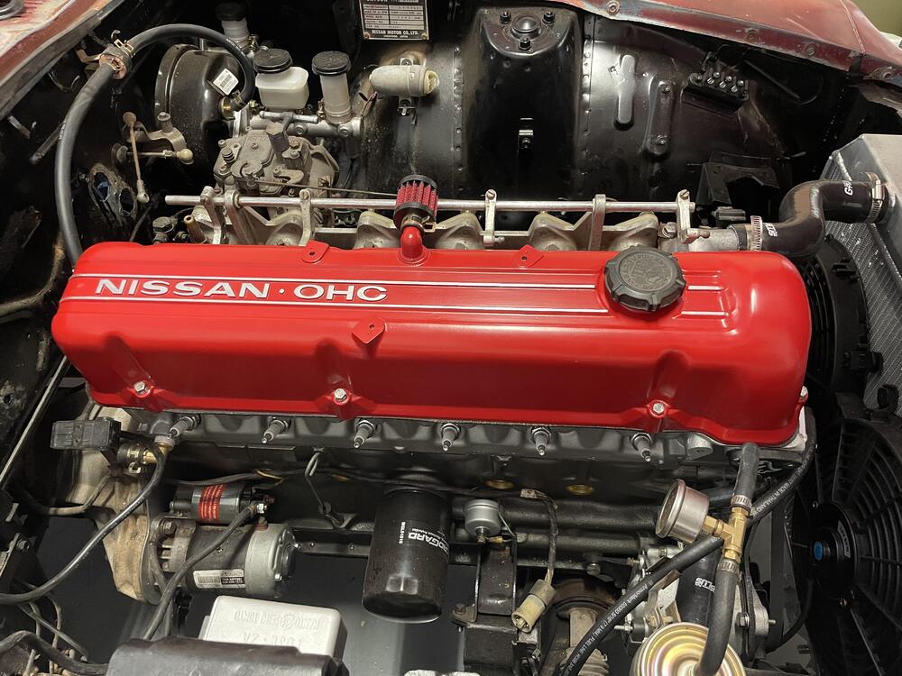
I know I said I wasn’t going to do work on the Z because of the holidays, but maybe this counts as holiday decorticating?😅 I felt the bay needed a splash of color
-
Thank you @Captain Obvious!
-
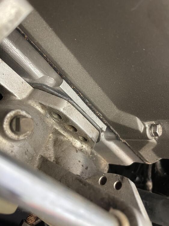
Quick question I haven’t had much luck researching on…in my last photo of the manifold, there are 3 locations for studs. The center, larger, is what I plan to use, with a smaller hole on either side. What are these for?
-
I would replace the metal too if I had access to a welder. Since you’re there, might as well. As for the sound deadening, I just did mine but only the front so total opposite of you! I can say it was definitely on there well. Dried ice helped a ton and made it come off in large chunks. Maybe do a test piece that’s smaller to see? Worst case is only about a couple hours to get it all off anyway.
-
The last photo looks like your heater core is bypassed? I’ve read about bypassing it and that it’s better to plug the fitting at the back of the block rather than looping it. I guess this is how the factory heater core works (stopping flow, not rerouting). Perhaps this could help?
-
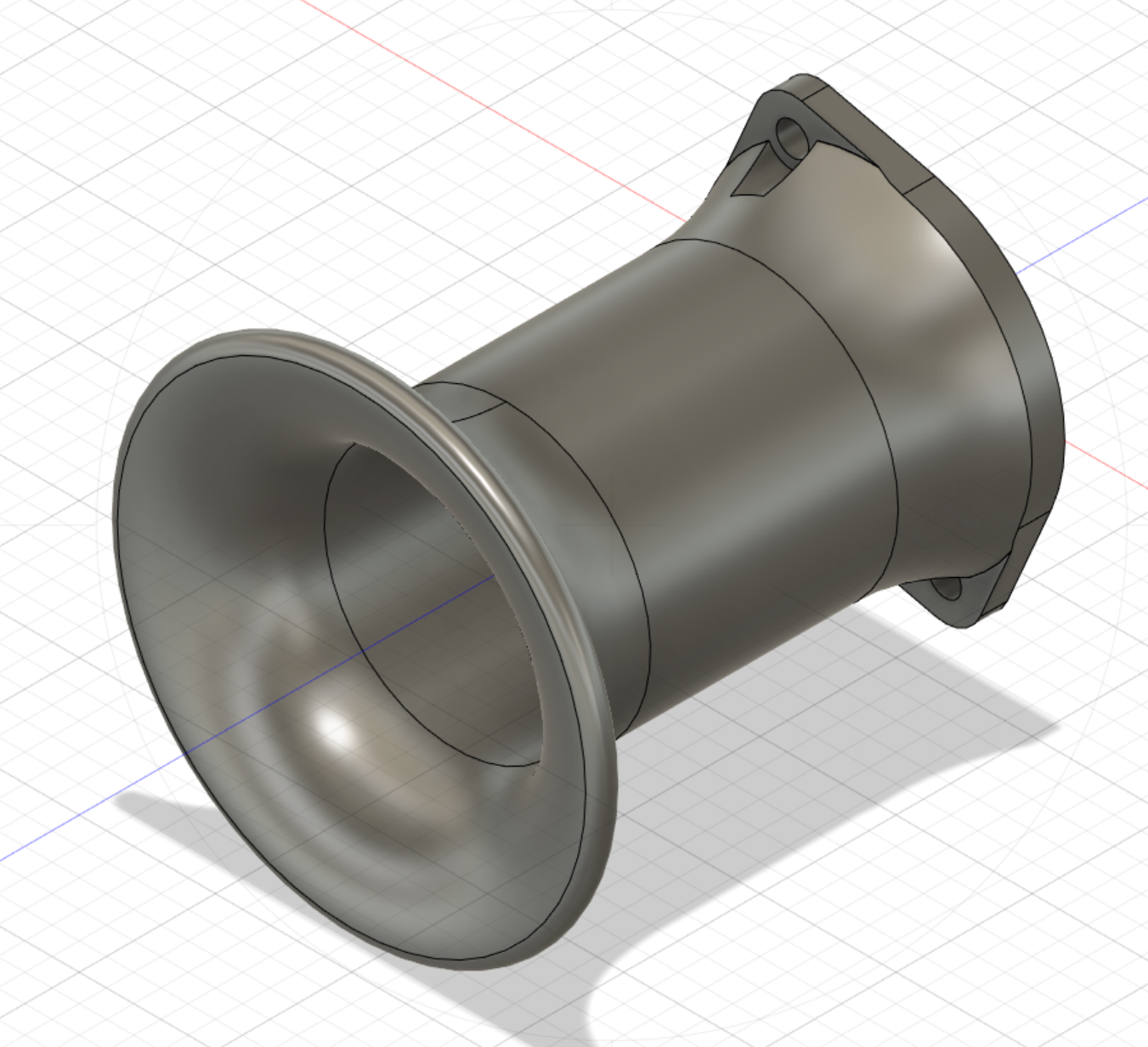
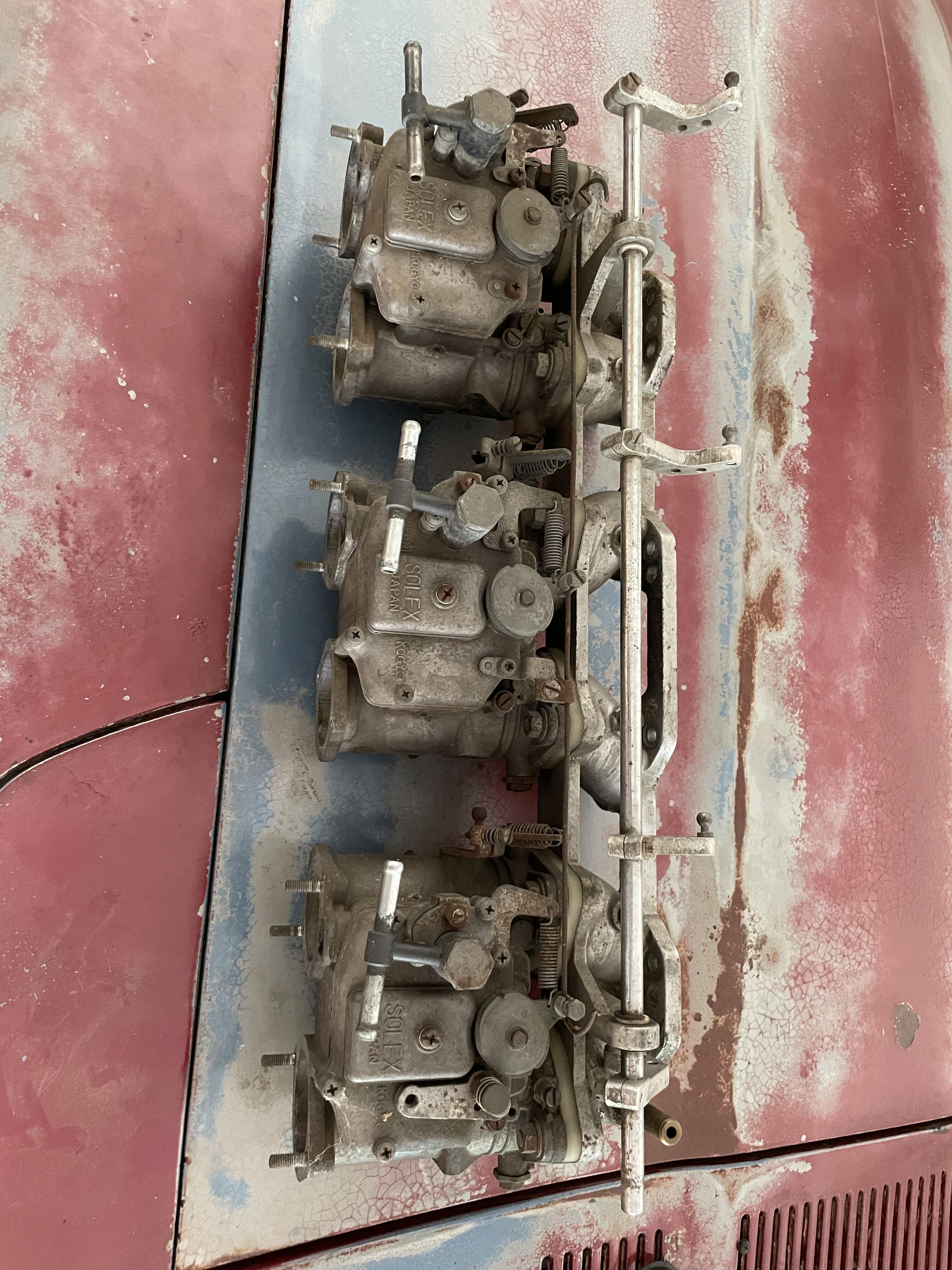
I spoke with Taka over at Kyusha House, very nice by the way, and we identified the manifold as a Mikuni. Even though there is no stamping, Taka let me know that there are version with and without stamping. I opened up one of the carbs to get a better idea of the inside condition and luckily it was not bad at all. No jets appeared clogged and there was no gunk in the bowl. I think (and hope) an ultra sonic cleaning will suffice. From there I would like to get all of the hardware plated so I will be researching recommended places to send the hardware off to. Also, it is nice that rebuild kits are easy to come by. Even the diaphragms are available which I will replace just in case. The jetting installed looked to be the original jets and choke size, so I will start with these and see how she runs. I will take a break from working on the car during the holidays, so I have been playing with Fusion 360 in my spare time. I came up with a simple velocity stack design, 100mm long. No idea if my initial radius are optimal, but its an easy change. I tried to maximize the diameter of the trumpet without causing interference with its neighbor. The flange was super easy to create! Up next will probably be a throttle cable bracket as I am missing that piece on my first carb. Everything will be printed in ASA, which should have enough heat tolerance for this application. A heat shield under the carbs will also be used.

-
Took out the old efi setup and manifold. Wow it’s so clean now without all these wires! The butterflies has a stamping of 175 which leads to the 44mm version. This should play nice with the high compression pistons and eventually a cam. I mocked up the new manifold for fit and just to get a sense of everything. I wasn’t able to find any stampings or markings on the manifold, does anyone recognize it by chance? I also noticed the top 4 mounting holes won’t fit the oem style bolt since the runners are so short. I’m assuming I’ll need to switch to a stud and nut setup? Next tasks to figure out are the mounting studs, linkage setup, choke pull (is this needed in Arizona temps? Sorry this is my first carburetor!) and rebuild kits. I’ll grab a low pressure fuel pump and regulator to get around 3-4psi of fuel and use my return line as well. I might print my own velocity stacks in the mean time since they go for a pretty penny.
-
Wasn’t expecting to pick up these beauties. But they came up locally for an amazing price and I couldn’t pass them up!! im not sure yet if they are 40 or 44mm or the intake manifold brand. I’ll be tearing them down for a clean and rebuild which should answer some of my questions. I can’t wait to get all of the ugly EFI components out of the bay…and one less harness to make! Time to read up on these bad boys 🙂

-
I agree with @Zed Head. My 75 tank looks different from yours. I have the vents on the side. Looks just like his second link 🙂
-
Let me know if you need any measurements. Mine 75 280 is still without an interior.
-
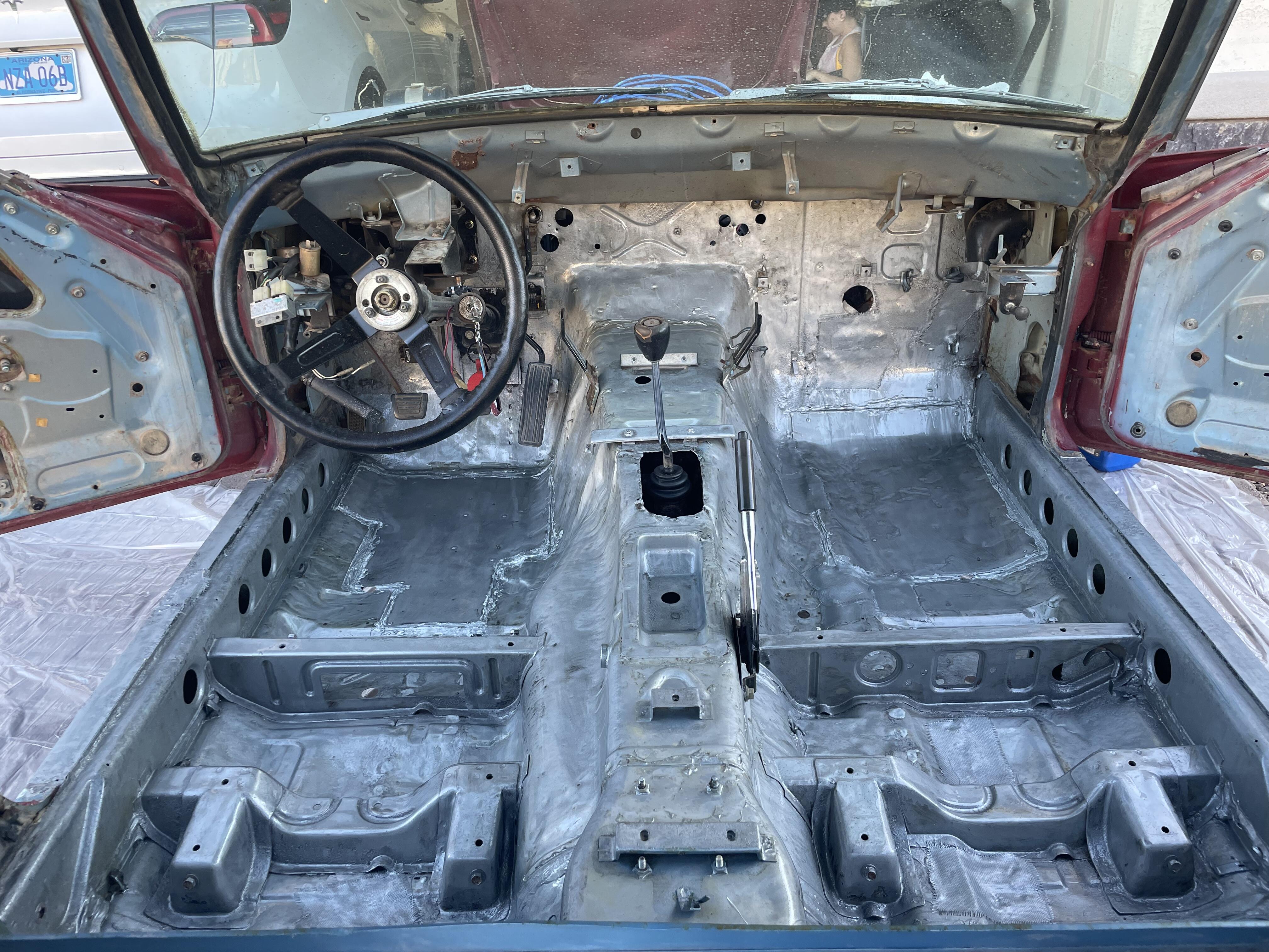
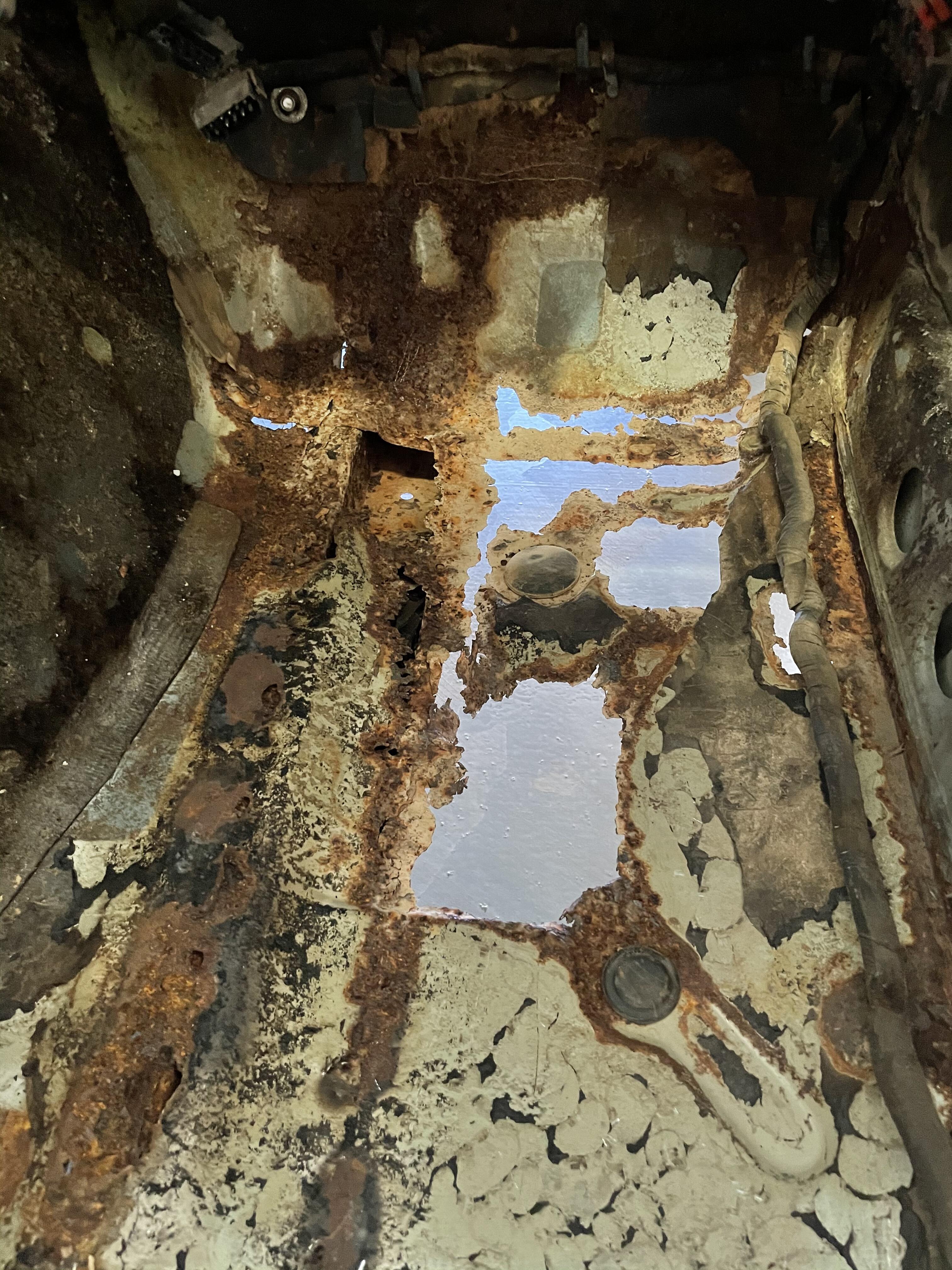
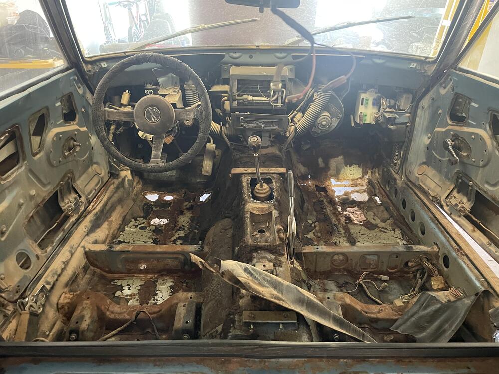
Looks great! One thing I regret not doing while my engine was out is cleaning and painting the front crossmember. Tackle that now if yours needs it (it looks good though!). It looks like you have new bushings which is nice! Start with a nice deep clean of the bay. As far as handling rust, I dont think my method is the preferred way (panel bond), but finding rust is the same. I poked and probed with a punch or screw driver in the problem areas for any rust. From there I used a flappy disc to sand away until clean metal was found around the entire rust spot. That is where I made my cuts. Check under the car too for rust in the floorpans. Just because the sound deadening looks okay, water could have seeped beneath. I discovered a few spots forming after removing mine. I used POR15 for my interior coat and highly recommended it. What sort of goals do you have in mind for the car? What steps next to you want to tackle? Engine, paint, interior, etc. Theres so much advice to be had! Depending on your goals, some may recommend a rotisserie to start stripping the underside.
-
Thank you, I appreciate it!
-
@Zed Headhas a great point. Don't just pull off anything you don't like...which is how my first post may have sounded. I know I am going to run aftermarket EFI in the near future (and alot of my items were non functional) so it was something I was okay with for the short term, rather than spending time and money on a temporary use. There are many things in place that on their own don't seem like they do much, but all together add up to a much greater impact.
-
I too removed nearly all of the emissions and "extra" items on my 280. EGR, Cold Start Valve, BCCD, Carbon Canister, PCV system (filters instead), AAR, and also the water temp sensor. I have alot of extra wiring now, but I planned on redoing my harness soon so I just tied them out of the way. I found a good thread on hybridz that listed the majority of the items: Carbon Canister (surrounding area will smell like gas after you shut it down hot, gas fumes in the engine compartment). No performance benefit. EGR Vacuum line - this will shut off the EGR permanently. You can also remove the EGR entirely, but you must make a block-off plate. No performance benefit. Injector cooling fan - you probably did this already. No performance benefit. TPS - throttle position switch. May cause idling or WOT issues. AAR - you will have a slow idle when cold, may stall out. No performance benefit. Idle speed adjustment - see above. No performance benefit. PCV system - underhood will smell like blowby if you have any. No performance benefit. BCDD lines - actually removing unit may require taking manifold off and making block off plate, not sure. No performance benefit. Ported vacuum system, including TVV and all lines. Move distributor line to manifold vacuum. Adjust base timing accordingly, remove 12V advance if desired. No real performance benefit. Coolant lines that run to the AAR and throttle body. Cold Start Valve - May cause extremely cold starting problems. No performance benefit. I do recall reading that the stock Z efi system is designed to be used with a rising rate fuel pressure regulator. A drop in vacuum (open throttle) adds more fuel pressure (more fuel) and Higher vaccum (closed throttle) reduces fuel pressure (less fuel). But I am swapping to a new fuel rail with a new regulator so I am not worried. During my research, I also got the vibe that it was sacrilegious to remove anything the Datsun engineers installed. Even if I sell a Z part locally and take to the buyer, 50% of the time they ask me why I removed what I did. But it didn't stop me, nor should it stop you if thats what you want to do to your car. If we all followed the FSM, none of our builds would be interesting 🙂 But take what I did with a grain of salt as my Z has only been around the block twice 😄
-
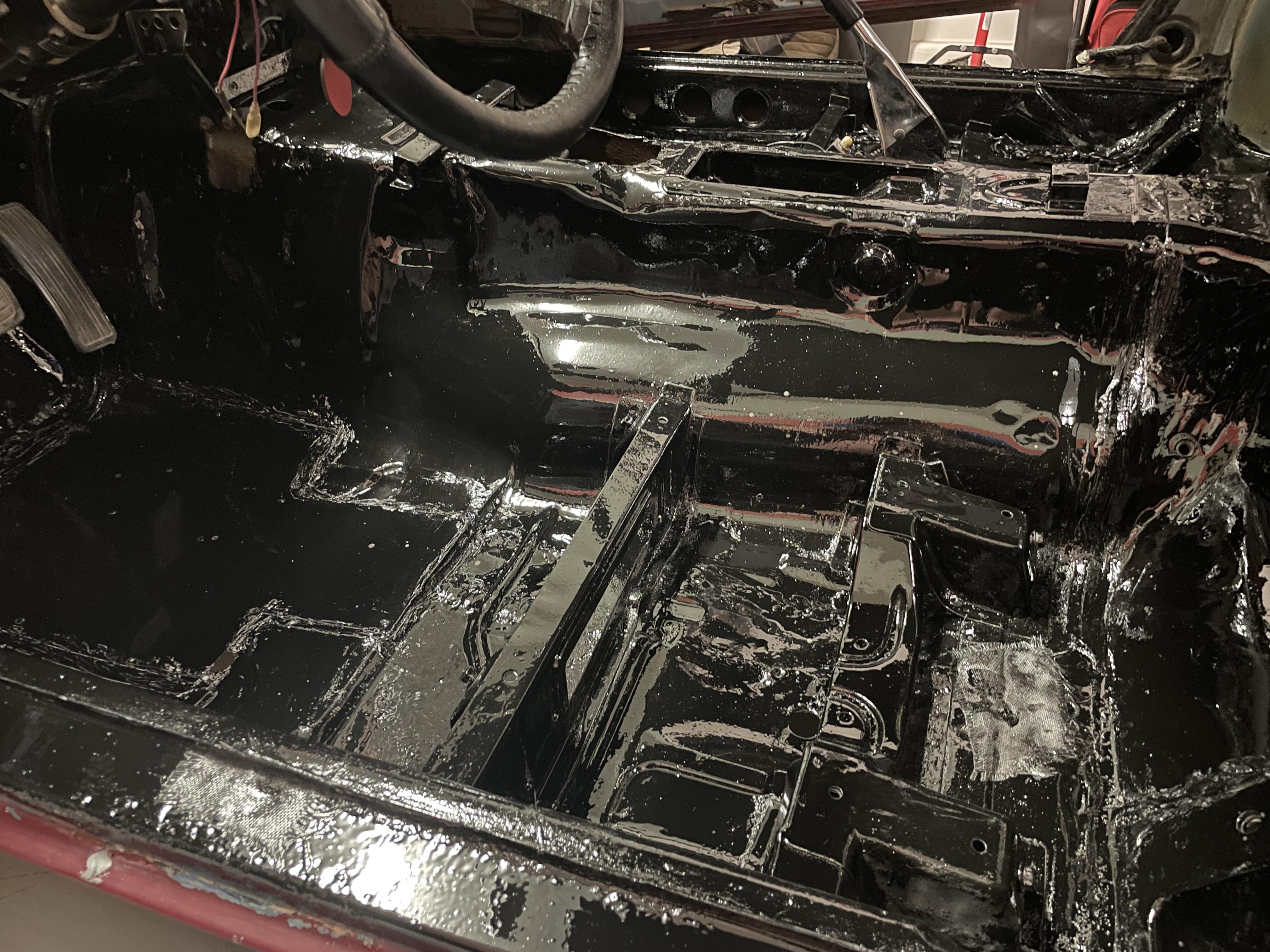
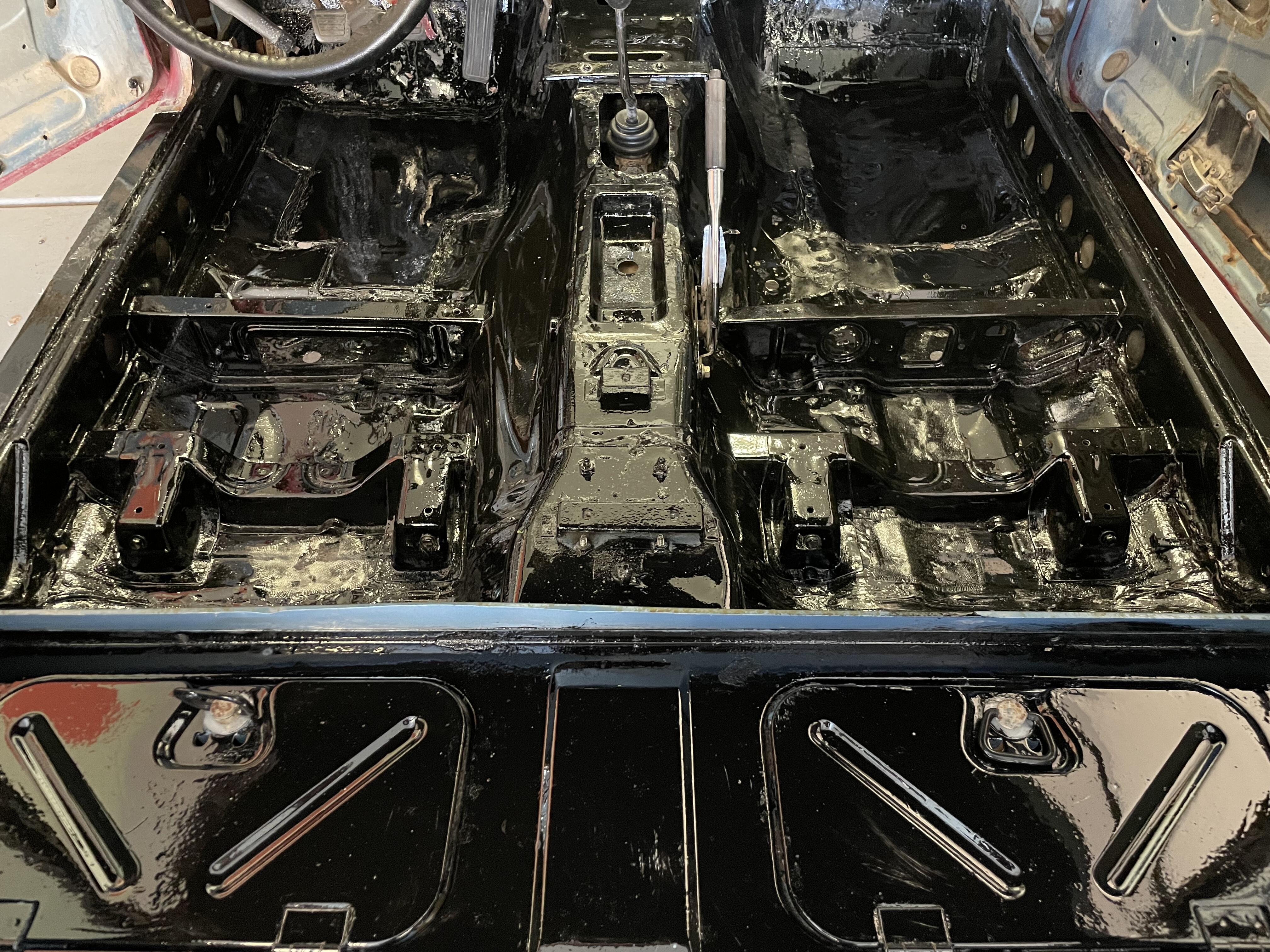
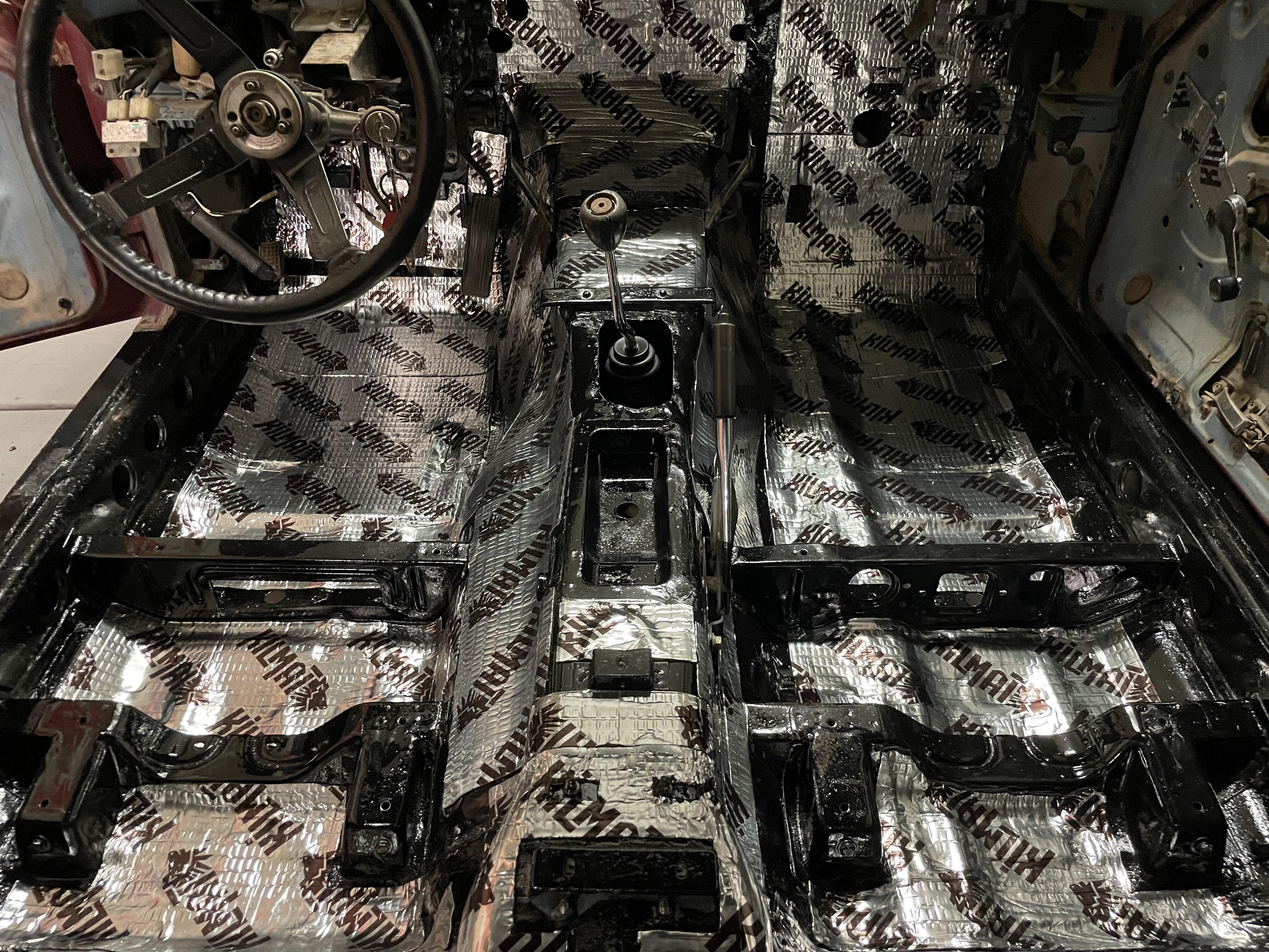
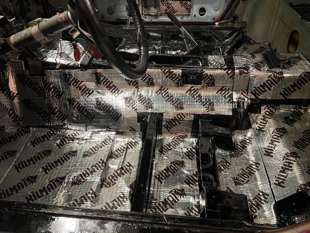
Worked on wrapping up my flooring this weekend. Started off with POR15 base coat which was silver. I used their fiberglass fabric to fill in any extra pin holes I had laying around. No longer in the stone ages like the Flintstones! Then used the gloss black for the second coat. This helped a ton with finding where I missed a second coat. If I were to leave the floors raw, I would use their top coat. It adds UV protection and a satin finish. The gloss black shows every imperfection! But it does level extremely nicely. No brush strokes in site. Lastly I used Killmat as my sound deadening. I started off with just trying to hit the main flat spots of each panel but I have way more material than I though I needed so I started to fill in the blanks. Overall I’m happy with how it came out. Not that it matters since it will all be covered with carpet 😅 But boy what a nice change to be able to sit in the car and not worry about getting tetanus or dragging dirt into the house. No more smells of musk and I won’t hear every rock and pebble 😊


-
Thanks that makes sense! Great idea to have a surefire way of the carpets fitting. If a 240z carpet isnt a good fit in a 280z I'll follow that route. Edit: I think I found a good solution. Zspecialties has a 5 piece kit: 2 front carpet pieces, 2 underseat, 1 rear cargo deck carpet. Seems to be just what I am looking for. They even have sewn bound edges and they have a high quality dense padding glued to them!
-
I am trying to decide on what sort of interior I want for the Z. After seeing how well @Av8ferg turned out with the diamond stitching, I am leaning that route. Looking at carpet kits, most, if not all 280z kits have the carpet on the transmission tunnel. Which makes sense as it is the OEM style. Ideally I'd like to find the floor pan carpet pieces on their own and then DIY the vinyl for the transmission tunnel, kick plates, and rear bulkhead. StockInteriors has the kits for the 240 and 260 which contains all the parts I want, but before I buy, I want to confirm it would fit a 280z? 🙂