Barefootdan
-
Posts
275 -
Joined
-
Last visited
Content Type
Profiles
Knowledge Base
Zcar Wiki
Forums
Gallery
Events
Downloads
Store
Blogs
Collections
Classifieds
Everything posted by Barefootdan
-
That’s perfect information. Thank you @Captain Obvious I’ll be sure to grab a switch rated to at least 10amp.
-
The 12 pin connector for the rear sub harness will be inside the cabin, I just grouped these into a sub harness as it will be the only wires headed to the hatch area. The fuel pump and sender is the 4 pin connector which is what will exit the cabin. The gauge next to the pump is actually the sending unit that gives the signal to the gauge. I will rename 🙂
-
Thank you! Switch panel is going in to trigger fans, lights, ignition, etc. Rather than using the stalks and key. Good point with the fuse box. It is just a single buss bar for power, so everything will be powered when I trigger the main power relay. I think I am okay with this. I may work the headlights, horn and dash clock to have constant 12v, but I dont think anything else needs it. I wont have a radio with clock and I cant think of anything else. Shunt is staying for now 🙂 If my ammeter is toast, I'll swap it for a voltmeter.
-
I will also be switching the switch panel to a switch 12v rather than a switch ground (thats alot of switches!). I had one question pertaining to the starter solenoid. The small yellow wire that activates the starter seems to be low amperage. Why does this need to go through a relay? Can I just go from fuse box -> push button switch -> solenoid? I recall testing my starter in basically the same principal by using a jumper lead directly to the battery terminal.
-
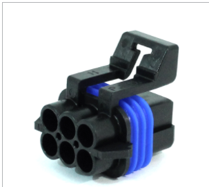
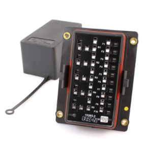
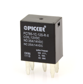
Thanks! I originally started by using the factory layout in my first draft, but then the more I removed, the less it made sense. I would have one switch all alone in the middle of my wires 😄 I grouped up similar items in this recent draft, for which I might do main connectors between. Thats right, the goal is to use modern relays and connectors wherever possible. For instance, the hazard switch is a 6 pin old white connector. I'll cut this off and use a a Aptiv connector combo like this: Some items will require me to re-use the old plug or find a remanufactured plug if mine is too cracked. Such as the Shunt. The plug goes directly into the box itself. For the fuse box, I am leaning towards the Eaton Bussman box: It can hold 10 fuses and 5 relays. It uses the micro fuses which I like much more than the chunky style. I will probably need more fuses, but I can buy a second one if needed. They're small 🙂 The relays that fit into this box are nice and small as well: But for larger items like the main power relay, headlights, and fans, I will use a beefier unit in the engine bay. In addition, there is alot going on in the FSM wiring diagram that doesnt pertain to my non california spec, manual, US car. So taking out those plus things I dont want like: Nuetral Swtich, BCCD selonoid, all air conditioning condensor items, cold start valve, interlock relays, auto antenna, seat belt switches, rear defogger, and buzzers. It will help going forward with less clutter. And lastly, that colored diagram wouldve been amazing a week ago 😄 I will definitely be using it as a reference going forward. I need to go through and proof read my diagram again anyways.

-
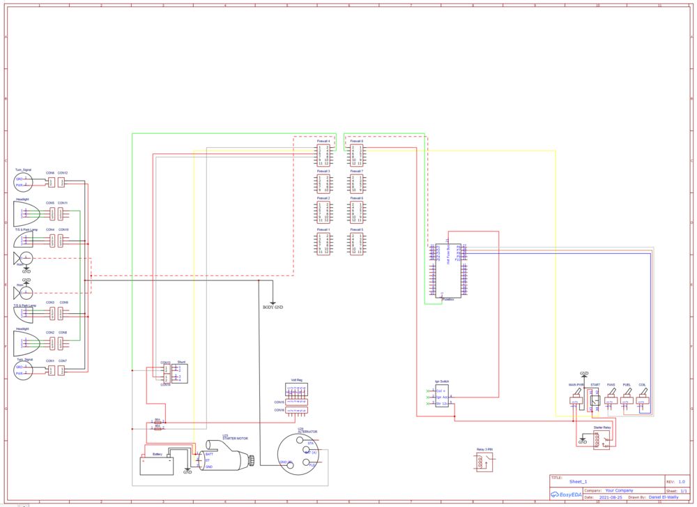
Cleaned up the diagram a bit. Theres still some things I'm not 100% sure on but I will probably be better off figuring out when I have physical parts in my hands to test with a multi-meter. Hazards and Turn signal relays are all intertwined and I want to convert to a modern flasher so I left some connections blank for now. Anyways, attached is PDF of what I'm going with for now. I'll start a contents table to price it out and see if it's cheaper to go full DIY vs a kit like painless+connectors. My eyes need a break from monitors 😄 I'm going to the garage! I still want to go back and clean up wires that are post connector (i.e. the oem wires) so I have an easier time converting. For now, it wont match in this iteration. Schematic_280z Body Harness v2_2021-08-30.pdf
-
Thanks @Zed Head that’s makes sense
-
Made tons of progress over the weekend and finished my first draft of the harness. Now I am doing a second round to clean things up and combine repetitive items. Quick question on relays. I know we can do 12v activation or ground activation. Is one preferred over the other (or is there a specific relay that needs 12v activation)? By the looks of it, ground activation is much simpler. I can run one ground to each of my switches in the panel and then ground those off nearby at the chassis. Rather than needing to run a 12v to and from the switch panel.
-
Good point about the interlock relay in the 75, I dont recall having issues starting the car without meeting all the necessary conditions. I'll be sure to check on mine. Maybe early 75s didnt have it like you say. And absolutely no offence taken! I dont intend for anyone to spend significant time to solve these issues, I will eventually. Just seeing if anyone has come across these in the past and may know off the top of their head. Although, its tough since they swapped wirings so frequently 😄
-
I wrapped up the body harness first draft today. I have a few questions from the 1975 wiring diagram. Some odd choices it seems, or maybe just artifacts from the scan? 1. The backup lamp switch for the M/T looks to have two wires, both blue, one to the rear lights and the other to the wiper. Is this just sourcing power? I assume I can grab 12v anywhere close then. 2. Yellow switch wire from the starter goes directly to the interlock relay. Can I bypass this entirely and route it directly to my start switch on my ignition panel? 3. The second wire down in the ignition coil resistor is a black/blue that looks to get power from the stalk on the start sequence. Can this power also be jumped from my start switch on my ignition panel? 4. There are black/white wires from the C4 and C5 connector that jump between each other before the firewall...and after...is there a specific reason? 5. The glove box lamp ground and speedometer ground look to connect directly to each other. I think this is a scanning issue in the document, but just curious 🙂 6. The black wire from the fuel pump goes through the rear harness and into the radio White/Black wire. Does it get ground here? Can I just ground at the chassis in the back? Thanks all!
-
Another update for the Z! Flywheel was dropped at the machine shop. He gave a cheap price since the block is still there and taking a bit longer to do. I figured why not... Ordered up some more parts! Who doesn't love daily stops from the FedEx driver....well maybe my fiancé...I should look into batching my deliveries into one day so it looks like I am buying less 😉 We now have (or on its way) MSA 3-2 headers, Z-Story JDM muffler, ARP head stud kit, Shifter bushings, clutch slave, lots of engine paint and misc. hoses, as well as some probably controversial items. I grabbed a "cold air intake" as my stock airbox is looking rough, $40 for a filter and piping is worth it for now. Electric fan setup, I know I see so many posts about these but my car didn't come with the fan, the fan clutch, or a full shroud. Also I picked up an ignition panel...more on that later. I was able to do a TON of cleaning lately while waiting on the block to finish. Lots of scrubbing and degreaser for the engine accessories. Valve cover and oil pan are painted up and looking fresh. I'll be sure to grab some photos. Also, I have been dreading cleaning up the fuel tank lines. When I first installed the tank, I was in a hurry to get the car running so nothing was secured or cut to length correctly. I finally redid the lines and tidied it up. For the large vent lines, I was able to use a trick I found here with 90 degree fittings for tight bends. Worked like a charm. And so that brings us to where I am now. I find myself with time, but nothing else to tackle until the block is done. I could start interior work, but I know that is going to be a massive project in itself. So of course I browse some more threads here and came across one for a harness rebuild...oh no. I did take the time back when I first pulled the engine to wrap the harness and clean it. But my god, the previous owners paint job has 90% of my connectors red and 90% of those are now cracked from removal (the price to pay for little rust!) It is just an eye sore and since everything is out of the interior...hell lets see if this is something I can do. I debated back and forth about an OEM style reproduction harness. I could just pull mine, and make a 1:1 copy. But, there are quite a few items I don't want/need anymore and I'd like to use modern relays/connectors whenever possible. Not only will this save some money, but probably a lot of headache! So it will be a modified harness, simplified for modern tech. It will be nice to have all the relays in one spot for once! Hopefully there are at least a few folks who will find this useful information. I will be designing a fresh wiring diagram that is colored and interactive if anyone would like a copy. I am picking and choosing strange items to keep or remove. Such as removing fusible links, that's an easy one. But I am thinking about keeping the Shunt for my ammeter. I don't want the door buzzers, the seat belt lights, emissions equipment, just to name a few more examples. My ignition switch works fine, although I am debating using an ignition panel to allow each accessory to be on its own toggle (fuel, ign, fans, etc.). When I first started up my car, lights worked, but not signals, so I will try to fix my connections now before resorting to having everything on a toggle. I like to have a balance of oem and aftermarket, I don't want a full on race car spec interior. If I do go down the route of toggle ignition, I am looking into hiding a kill switch, or going modern with an RFID sensor...kind of like a smart key. This also leads into EFI. I would like to go with a megasquirt system, maybe microsquirt, to handle that side of the harness. It'd be nice to remove the AFM and dizzy for modern solutions. Again, this will also let me run larger cams, remove unused wiring, and clean up the bay even more. This will all happen after the engine is back in the car and running. I don't want to try to tackle a fresh rebuild with also a fresh harness! Anyways, This is giving me something to design on the computer so I don't go crazy 🙂 below is a snippet of a proof of concept. These are absolutely not done and I mainly was playing around with EasyEDA to learn what capabilities it has. Shoutout to @SteveJ for helping me get started.
-
Thank you all for the help! I’ll be sure to reach out when I begin
-
Thanks Steve! I don’t think I would go for the task if I’m planning on an oem style harness. Finding oem style connectors would eat a ton of budget and buying a bulk pack of modern connectors seems much more accessible. But does this route (modern connectors) have any other unforeseen problems? Luckily I do have the room and feel the car is in a perfect time in its life for a refresh. The engine is out for rebuilding, the dash is disconnected for rust repairs. I’d be happy to document the process in my build thread, hopefully some find of value even if it’s not a factory style reproduction 🙂 I think this will be my winter project.
-
Oh shoot! 1975 🙂
-
I am wanting to tackle a project like this once my engine rebuild is complete. There are so many electronics that currently do work that I feel like starting with a fresh slate is just way easier. Half of my connectors are dry rotted and when pulling the engine, broke. I initially started buying easy to source connectors (fuel injectors, fusible link upgrade) but I am not very happy with where it is headed. Previous owner has crimps in random locations, and I am tempted now just to run new lines from pin to ecu. That leads me to a complete refresh.... When doing a modern harness update like this, what would prevent me from using modern style connectors? Amazon has bulk packs for dirt cheap that offer watertight connections if needed. I figure there are still a handful of relays or switches where connectors are not used (i.e. harness plugs directly into the relay rather than with a pigtail). For these, I would try to get lucky and reuse my current connectors, or upgrade to a modern switch as a replacement. Sorry if this comes off as naive, but it doesnt seem like too complex of a task, but just extremely time consuming! Are there major roadblocks (probably under the dash) that I am overlooking? 🙂
-
That’s exactly what I was referring too! Awesome to hear it’s good to go. Thanks for the tip about the front cover, I’ll be sure to take a look.
-
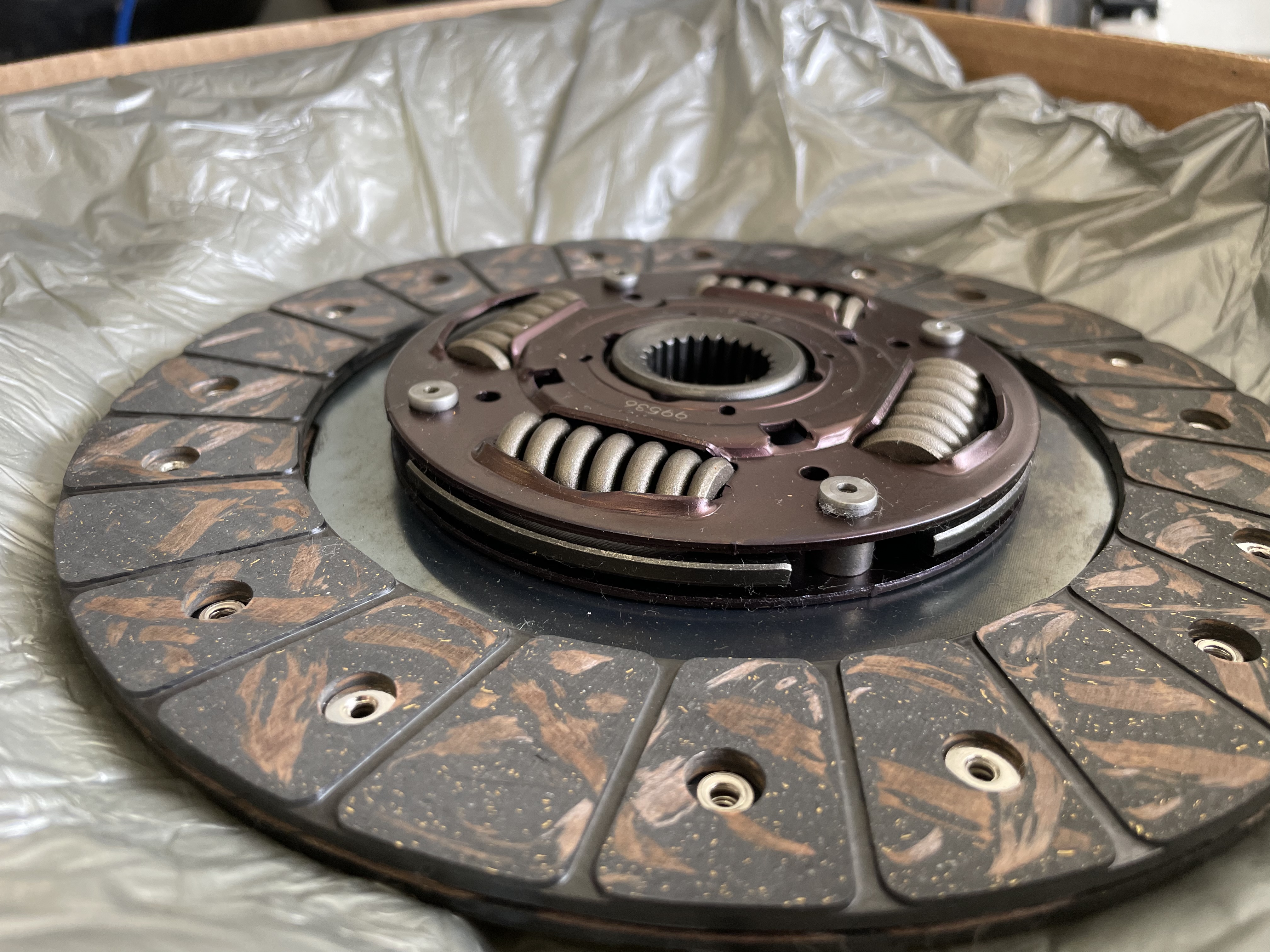
Thanks! First time doing any clutch work so was unsure on what to look for. It’s fairly cheap insurance to do it now while it’s already out.
-
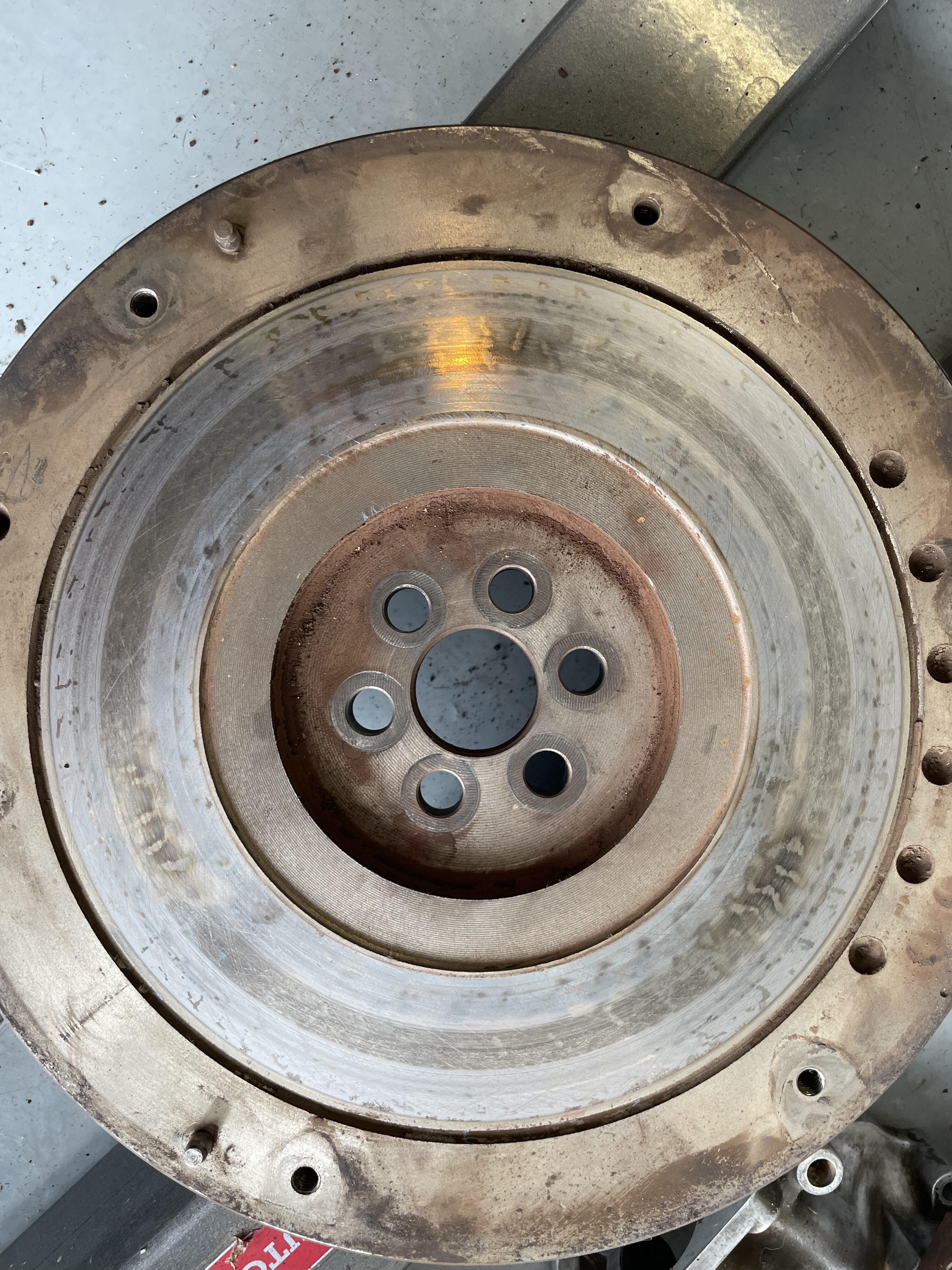
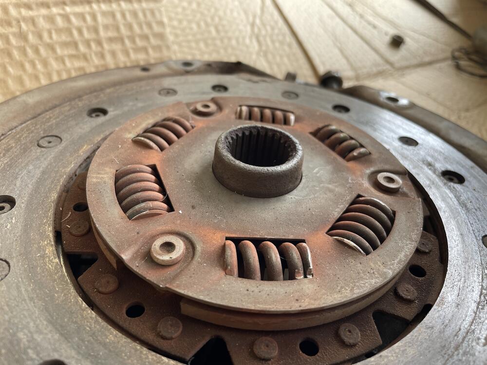
New clutch came in but looks a bit different than what I pulled out. It is missing the extended key slot. Is this okay or do I need to swap it out? I also attached photos of the flywheel to see what people think. Resurface or can I get by with a scuff and clean? Reading the Tom Monroe manual says if all looks good, just clean and scuff!


-

Restoring and prepping hardware for plating - the "easy" way
Barefootdan replied to inline6's topic in Open Discussions
Whats a good method for getting the grease off? I have a handful of parts with a THICK and sometimes HARD layer of what looks like grease caked on. Ive been using a wire wheel for the easier spots, but tight crevasses are still dirty -
I know we're all thinking it...😄
-
Ordered up the last (I think) of the parts I need for the build. Got some bearings (both main and rod), rings, belt, coolant hoses, ring compressor and installer, some assembly lube, clutch kit, alternator, output shaft seal, and engine/tranny mounts. last thing I need to get moving on is dropping off the flywheel to get resurfaced. Unless someone has experience with lightweight flywheels and highly recommends it, I’ll probably stick with the stock one for costs. The fun part is just around the corner. Can’t wait to start.
-
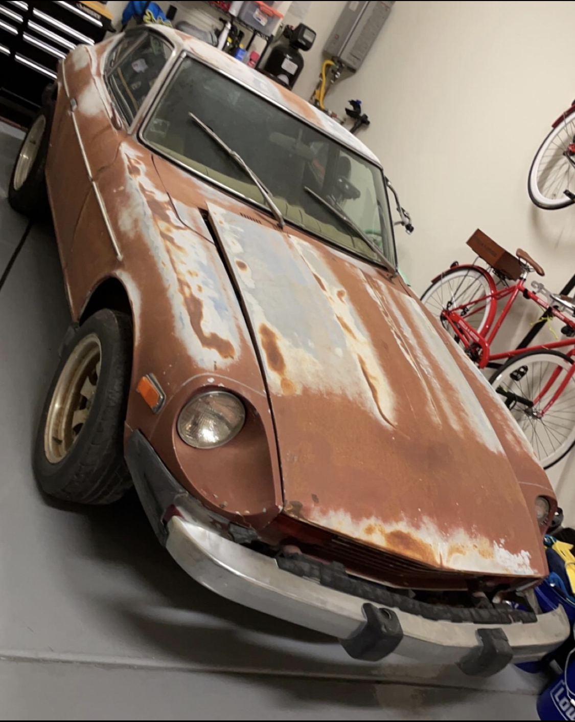
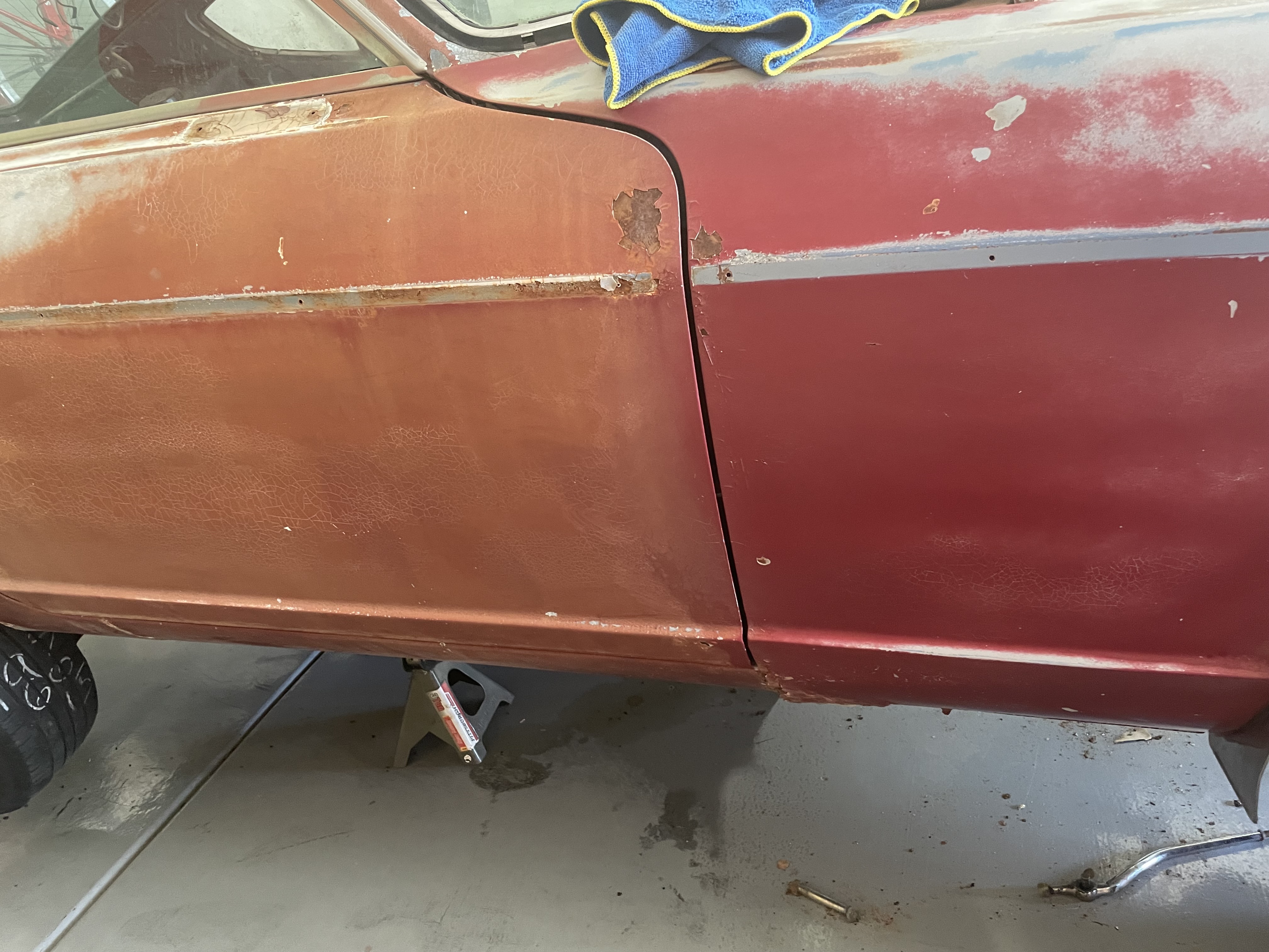
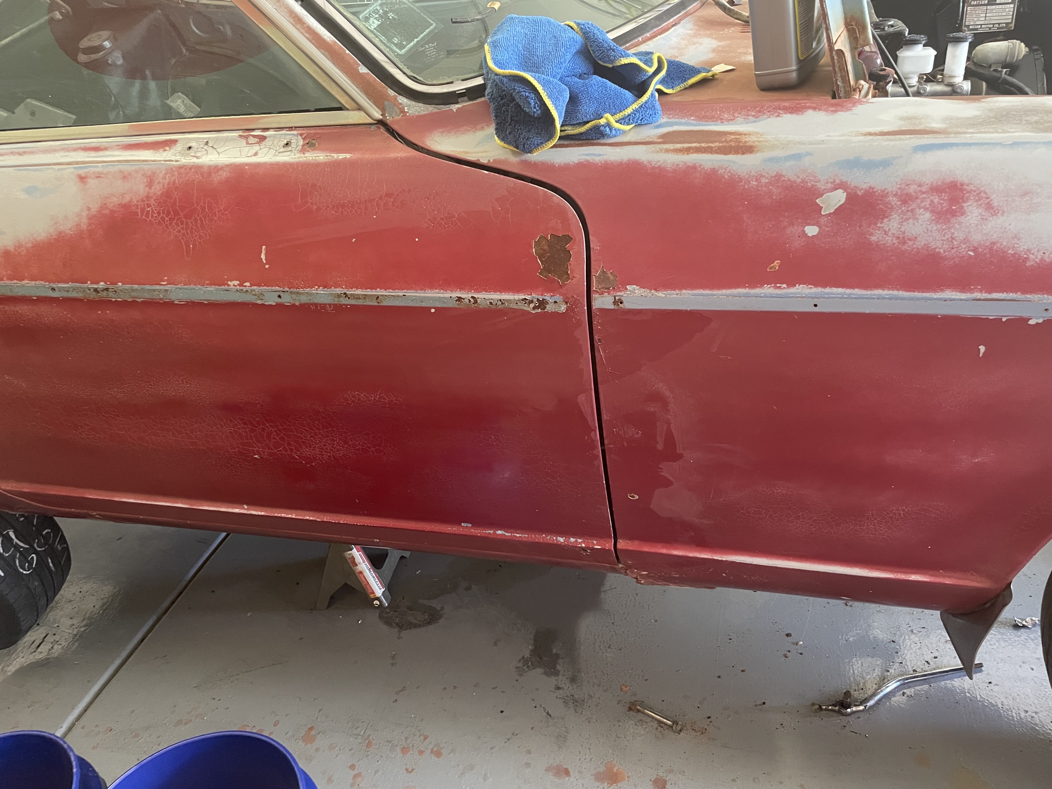
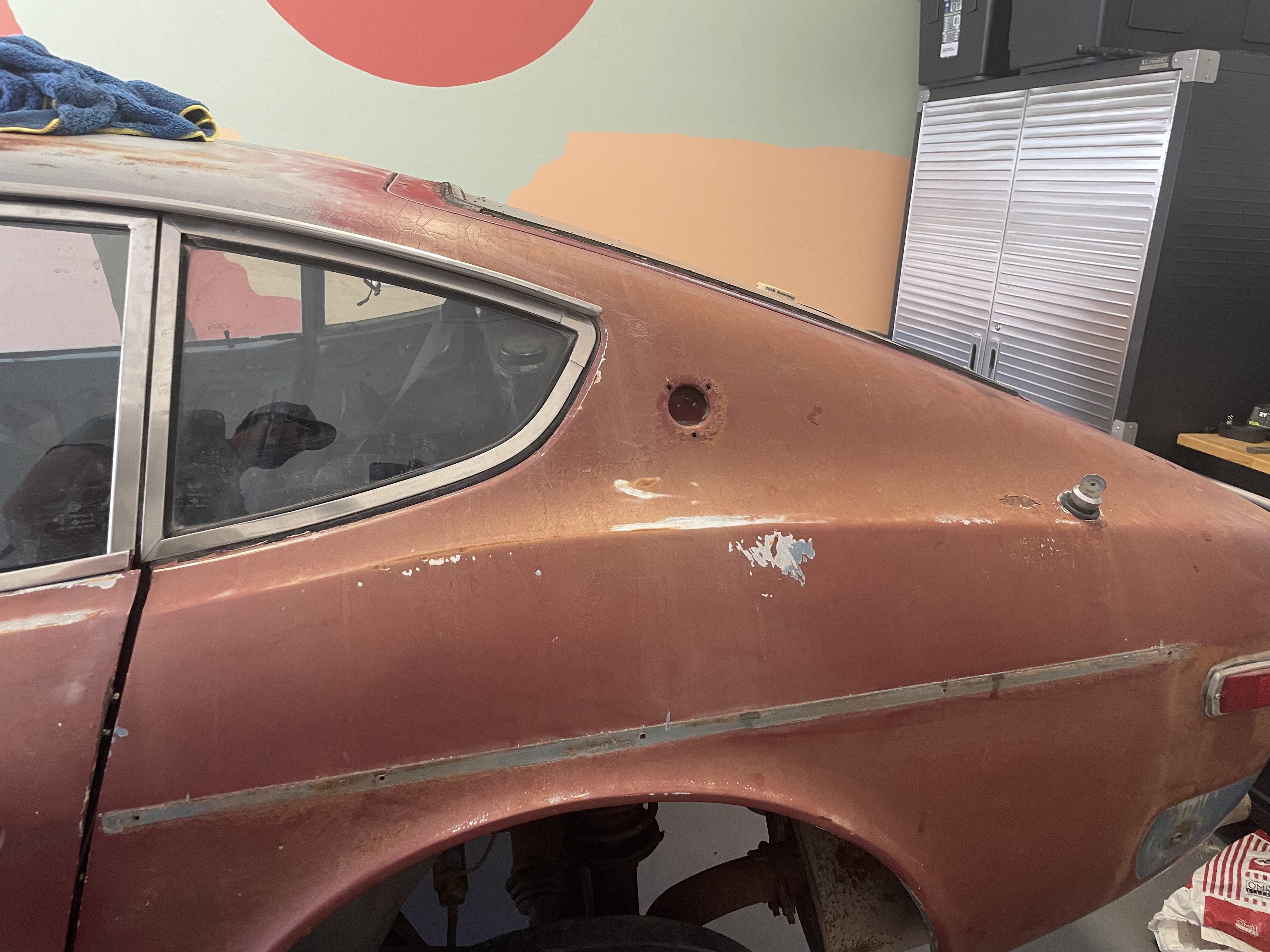
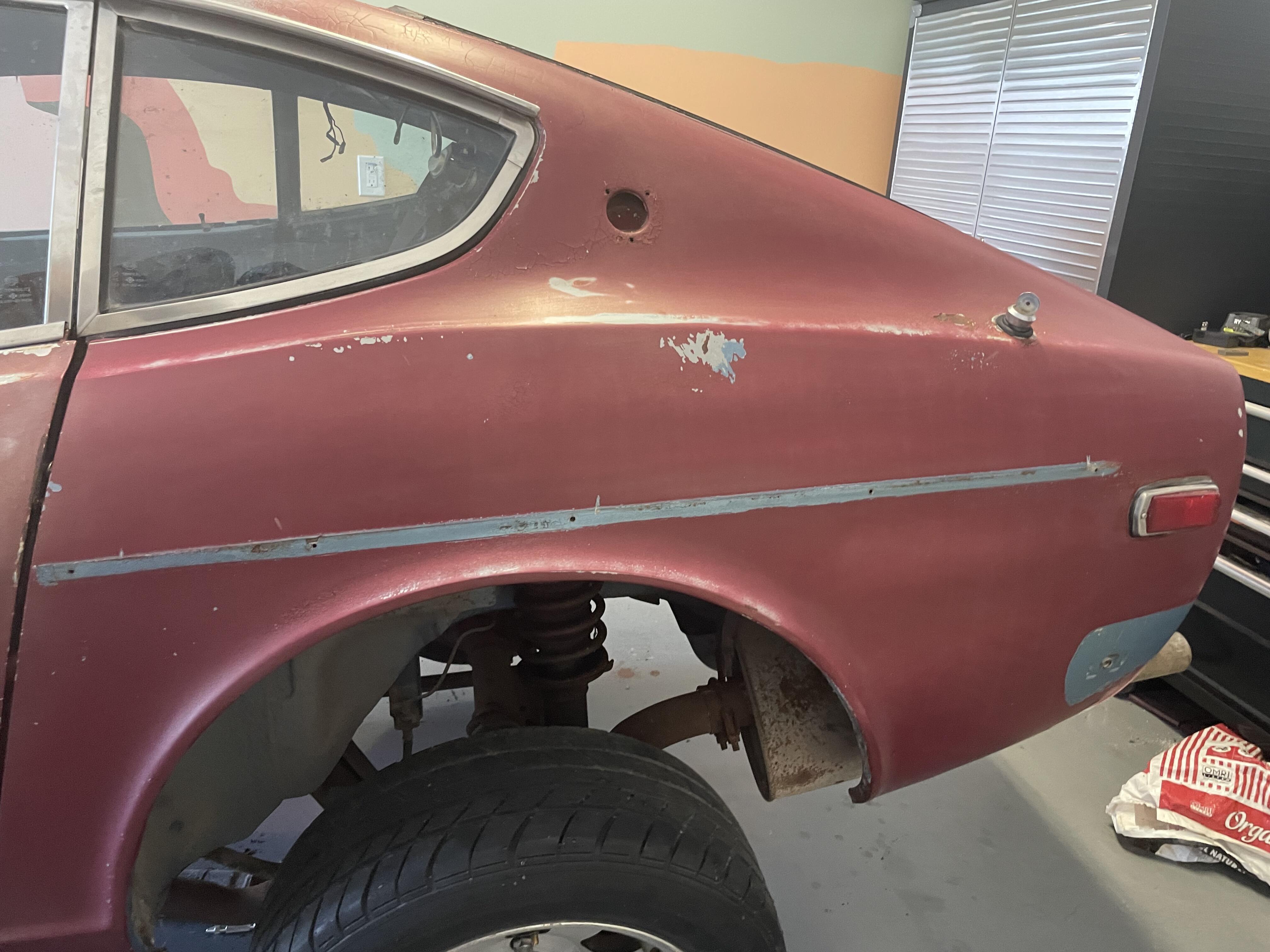
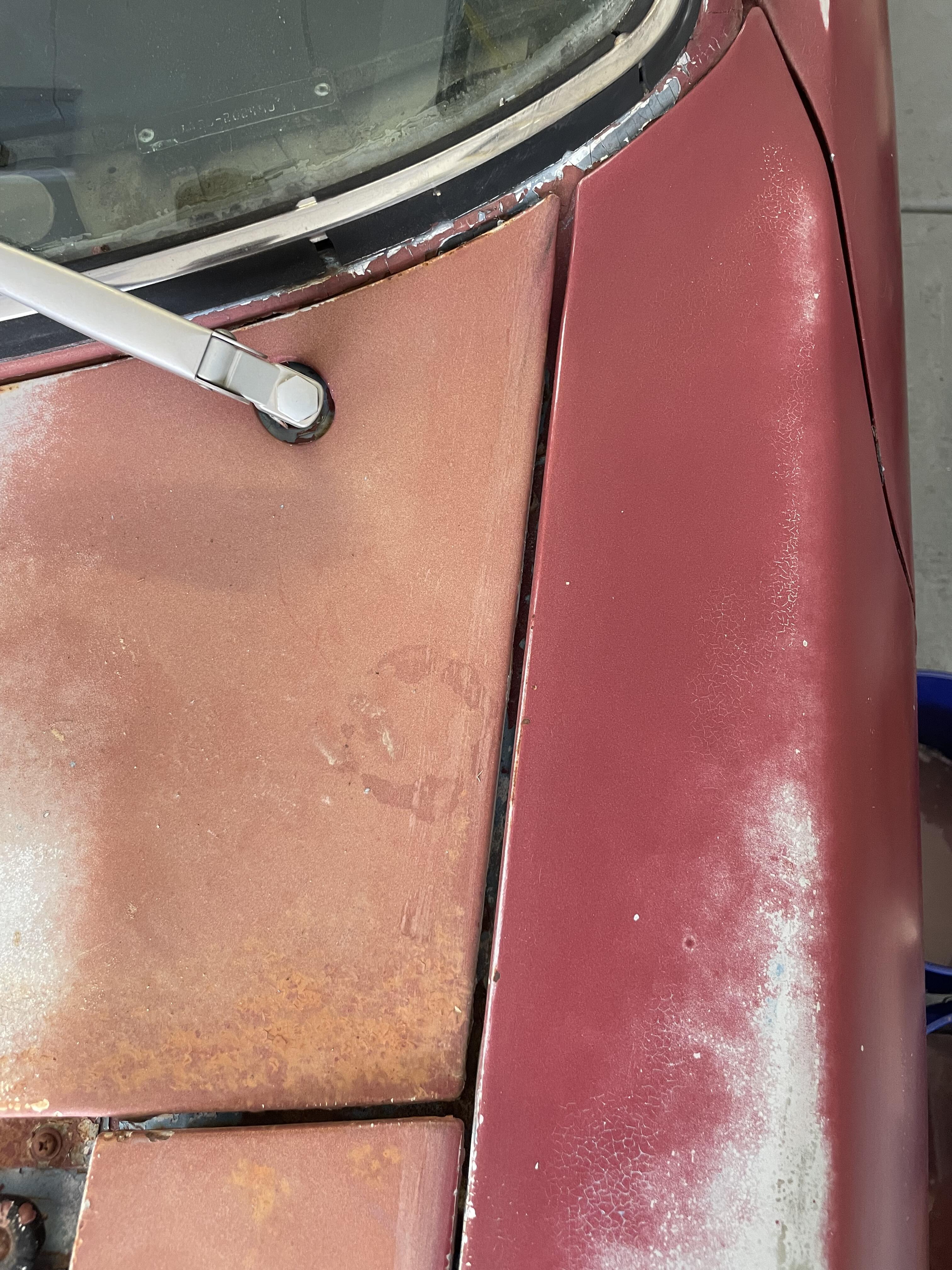
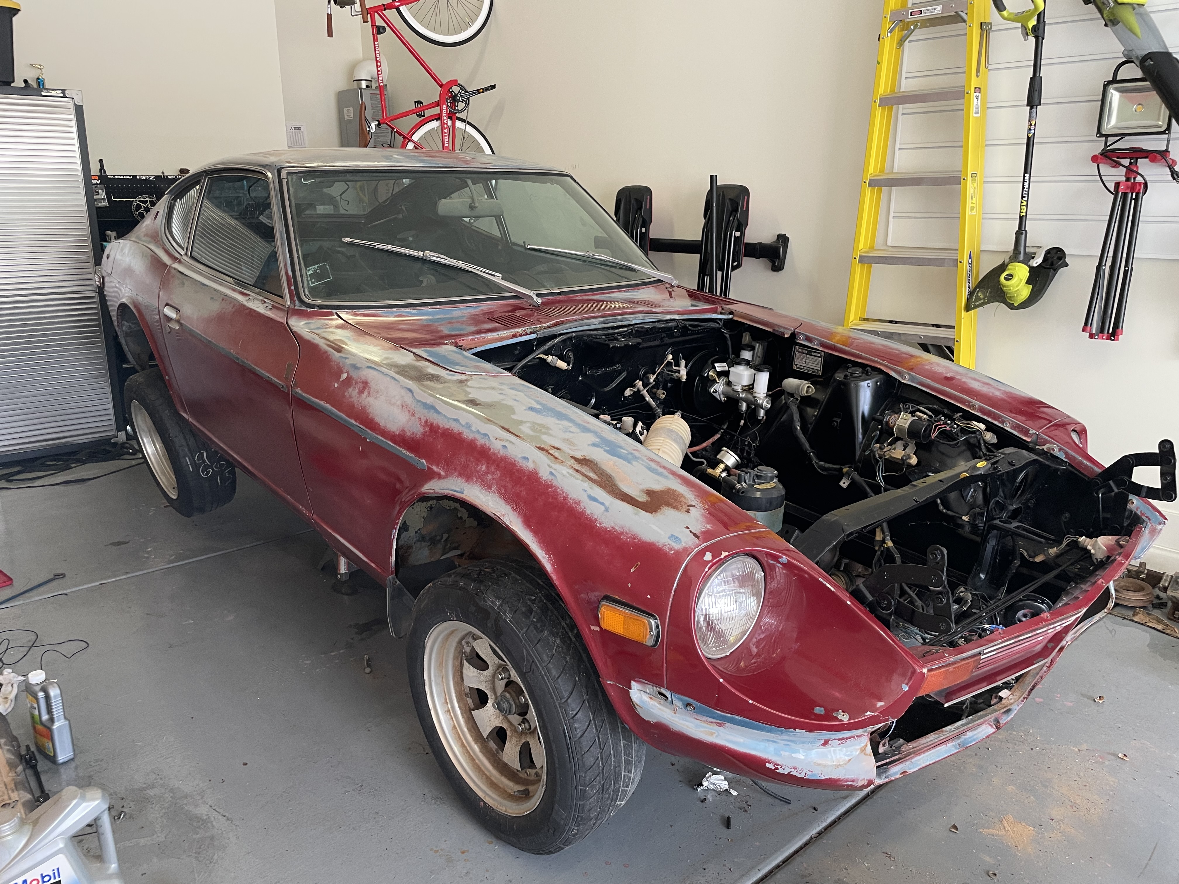
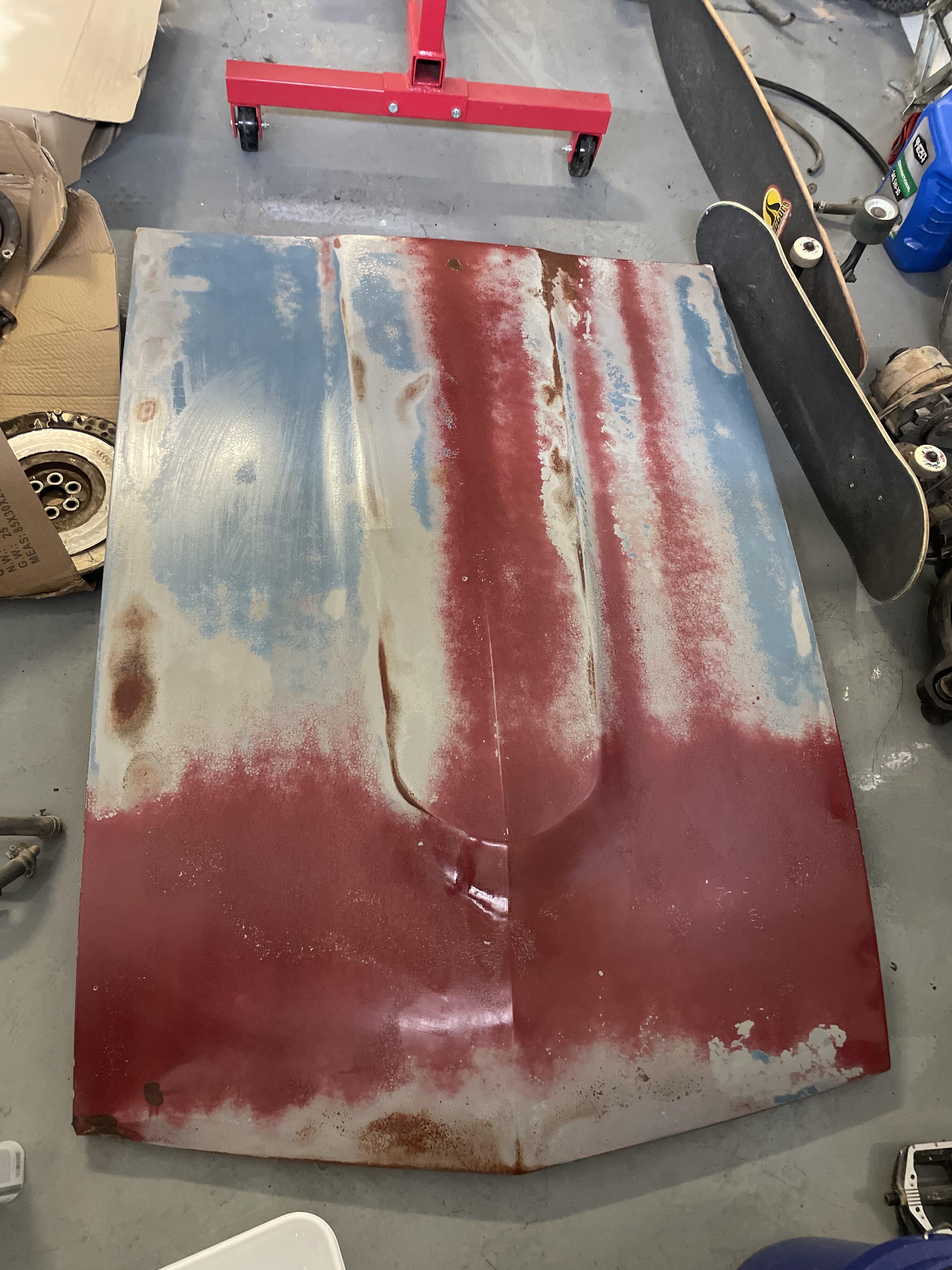
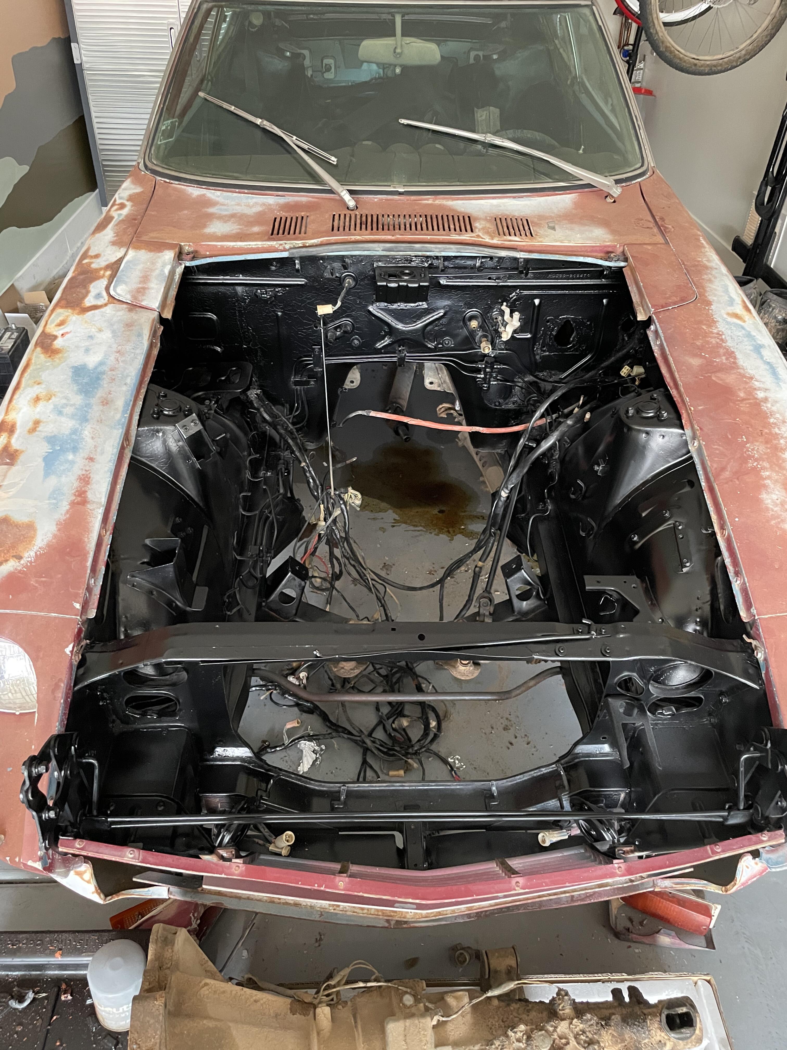
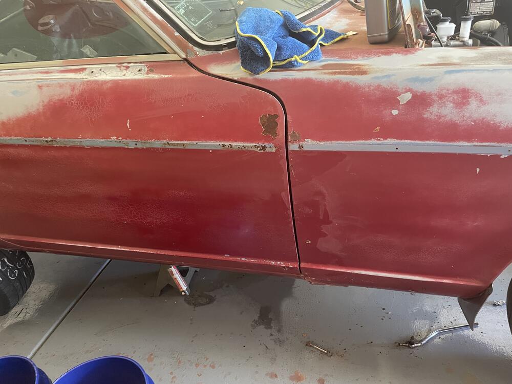
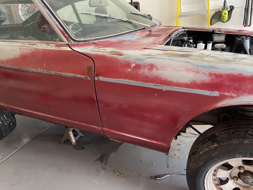
Thanks to @Zed Head for the idea of just cleaning up the body work for the time being. I spent the past couple days getting all the surface rust off the car. I originally thought that the paint faded to the ugly brown, but there was a nice surprise hiding underneath! I started off using a scotch pad and water. Then stepped up to some light CLR mix for the rust spots: As I went through, my process changed and I didnt like the look of the bare metal (where the CLR took off the rust). So I went back to just water and scotch pad. I had to remind myself that we arent preparing for paint, and just trying to clean up the surface! 🙂 I didnt like how rough the surface felt still after, so I hit it with some fine steel wool to smooth things up a bit. This was taken right after a wipe down so it is still moist in some areas and streaky in others. But the difference was amazing. Here are a few more comparisons: From there I went and grabbed some Penetrol to "seal" the paint temporarily. It gives a satin/gloss finish that also makes the colors and rust *Patina* some extra vibrance. Just a reference of where we started: The streaks on the hood leveled out, I just took the photo too soon 🙂 She absolutely deserves better body work in the future, but this will at least give me a finish that I can wipe down without my microfiber snagging immediately! 😄


-
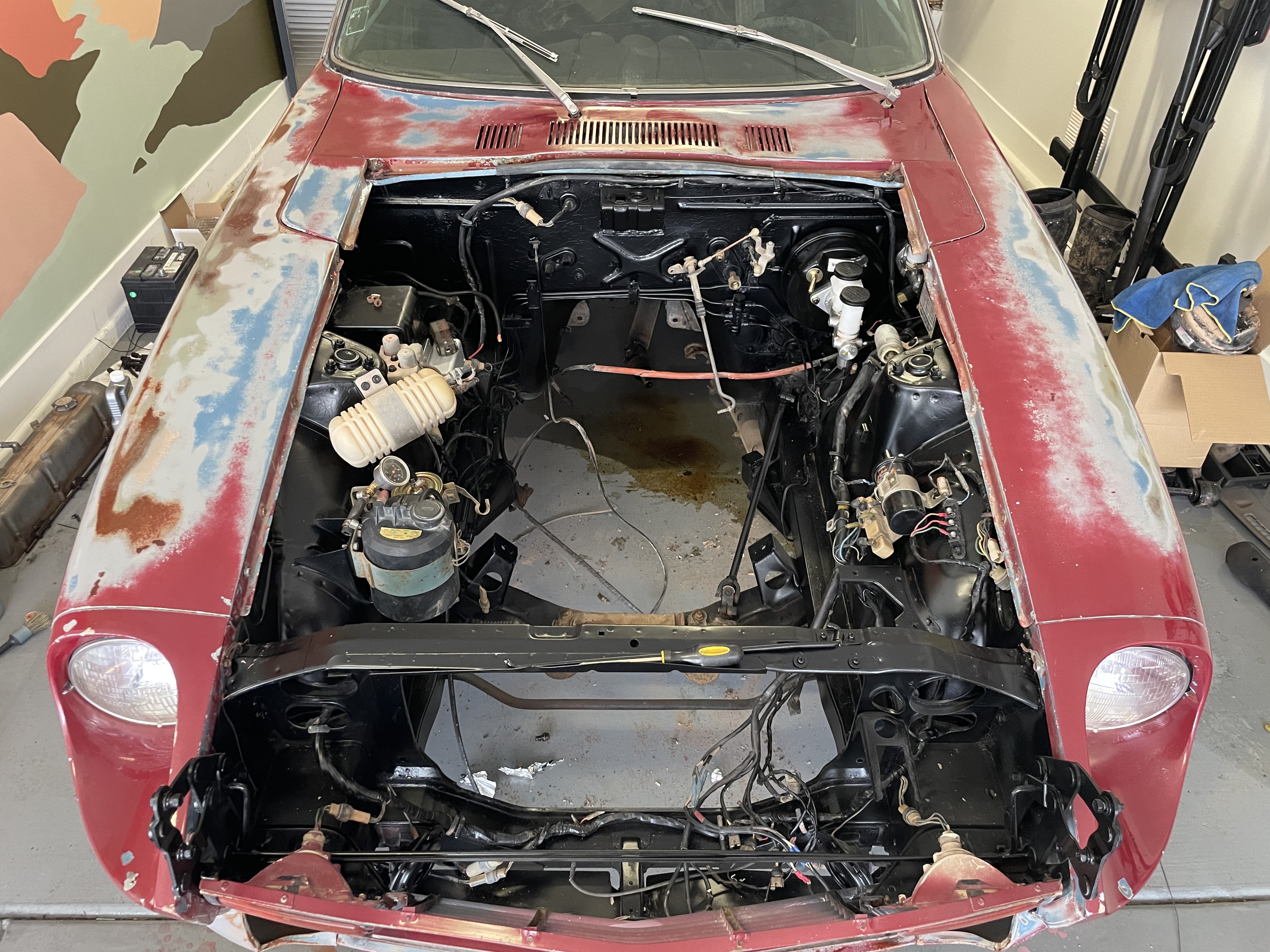
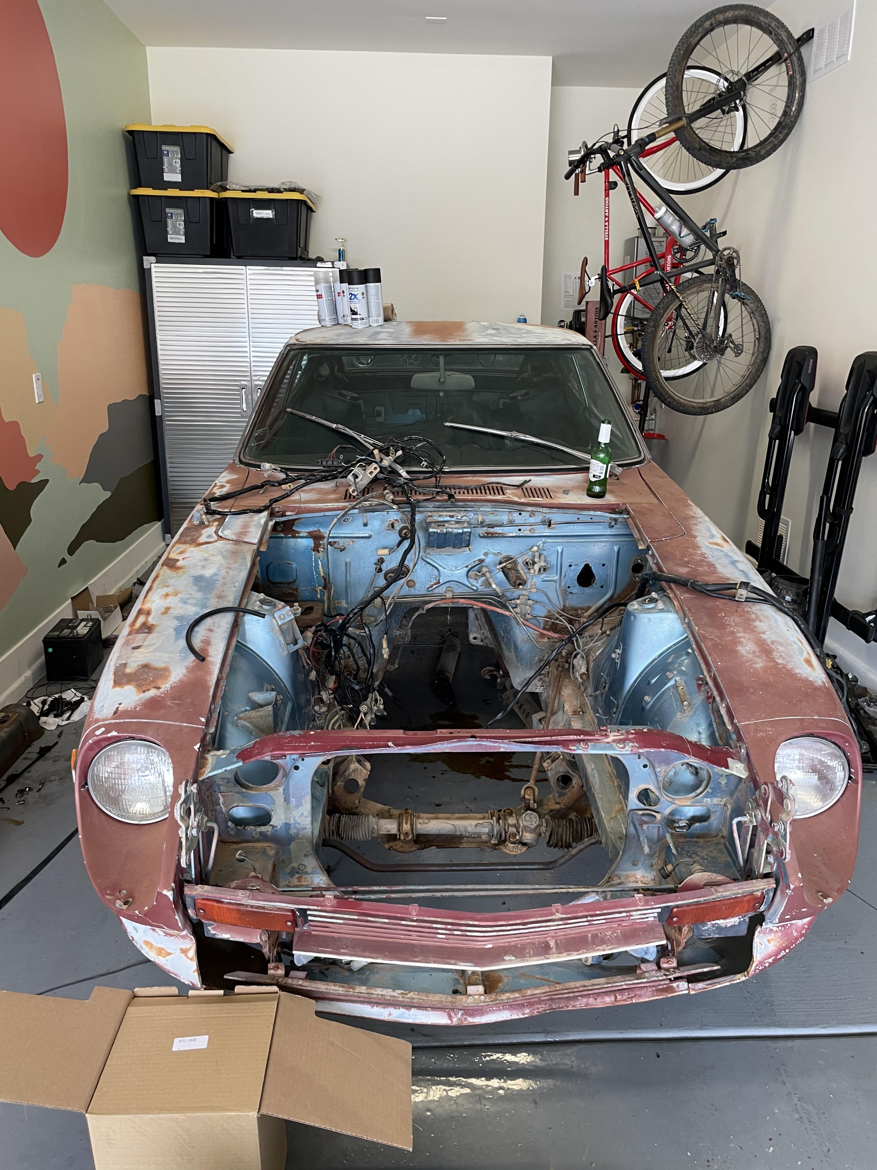
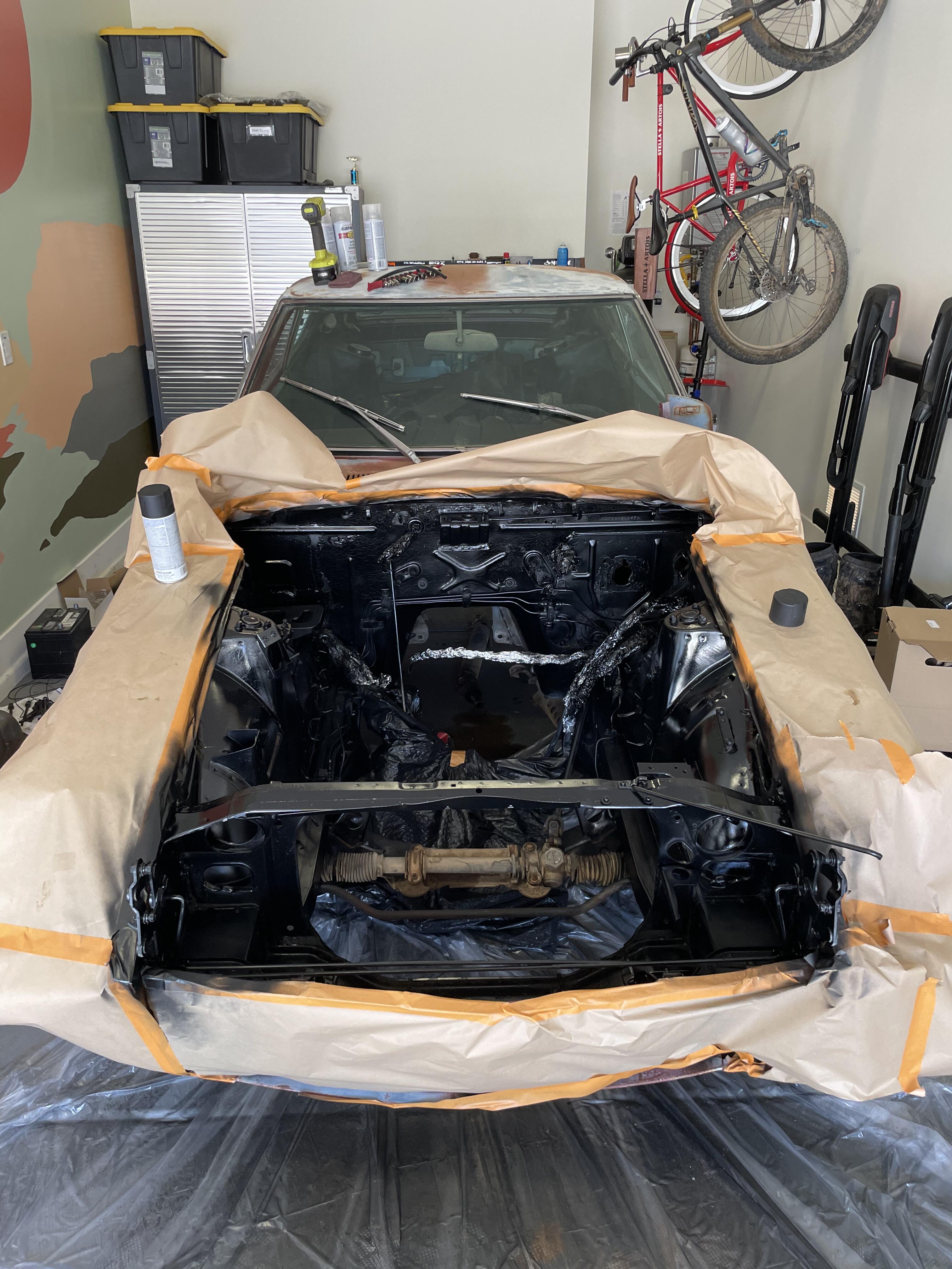
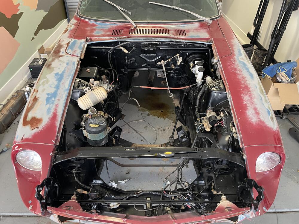
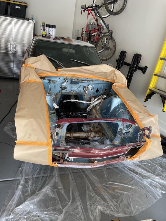
Finally got some new photos! The painting of the engine bay went smooth. It’s nothing permanent, but at least it will all be one color now 🙂


-
https://www.rockauto.com/en/moreinfo.php?pk=1101766&cc=1209204&pt=5220&jsn=126 Looks to be Tri-Metal!
-
I was able to find mains and rod bearings in stock at rockauto. Standard size, Clevite, for both. Rungs are by Hastings. Anything I should run away from?