Richie G
-
Posts
251 -
Joined
-
Last visited
-
Days Won
6
Content Type
Profiles
Knowledge Base
Zcar Wiki
Forums
Gallery
Events
Downloads
Store
Blogs
Collections
Classifieds
Everything posted by Richie G
-
Thanks so much. I'll hit the home depot and grab an assortment bag. Could these M5 be it https://jdm-car-parts.com/products/m5-screw-10-pc-set-for-inspection-lamp-fresh-air-ducts-brake-check-valve-holder-inner-fender-rubber-flap-fuel-filler-protective-panel?variant=40854607659117
-
Silly question but as I put everything back together I can't seem to find the right screws for the bracket that holds the pull knob for the under dash fresh air vent. I went through two boxes of old junk screws to even see if i can find a match but no luck. Anyone know what they are? They seem to be self threaded like some kind of sheet metal screw but nothing i have wants to bite and stay tight without tearing the threads. or is it some odd machine thread? i don't seem to feel a nut behind it or see any type of machine threads like most of the bolted connections.
-
Thank you both but I don't see any pictures in the last post cantech
-
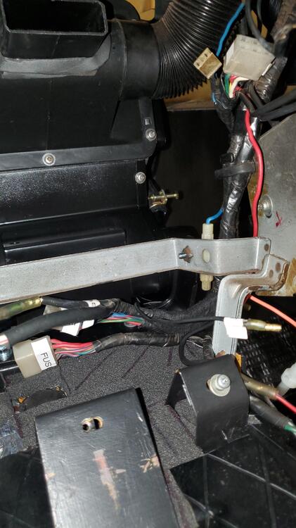
I've been searching for pictures but can't seem to find the right one. I'm starting to get the console and the heater control panel put back in and the previous owner had a hell of a mess of all the wires back there. So my question is do I route the pigtails for the fuse box cigarette lighter and defroster under the bracket for the radio or do I route it over the bracket for the radio. I've seen lots of pictures of the wiring harness Vinyl cover and all the wires hanging underneath the glove box side of the console but it's hard to tell how much of it is actually tucked in behind the heater control panel. I'm thinking it goes outside the radio bracket so that when I slide the radio in it's easier I just want to be sure before I start putting this all together here's a picture I took with the way I currently have it wired the main harness is coming down the side and then the parts I mentioned would be run under the radio to get to the fuse box cigarette lighter and console
-
Datsun 240Z Braided Heater hose set available
Richie G replied to esprist's topic in Open Discussions
Thanks granny good to know, will try that next time. Just not on the old fuel hoses 🤣 -
Datsun 240Z Braided Heater hose set available
Richie G replied to esprist's topic in Open Discussions
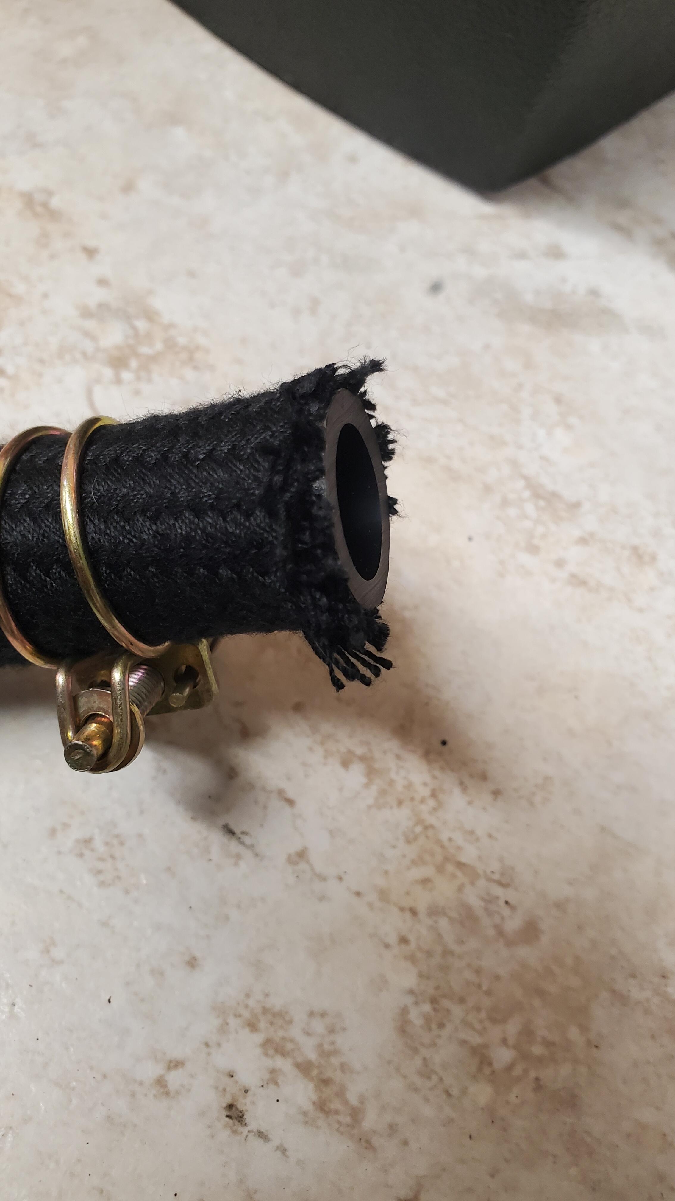
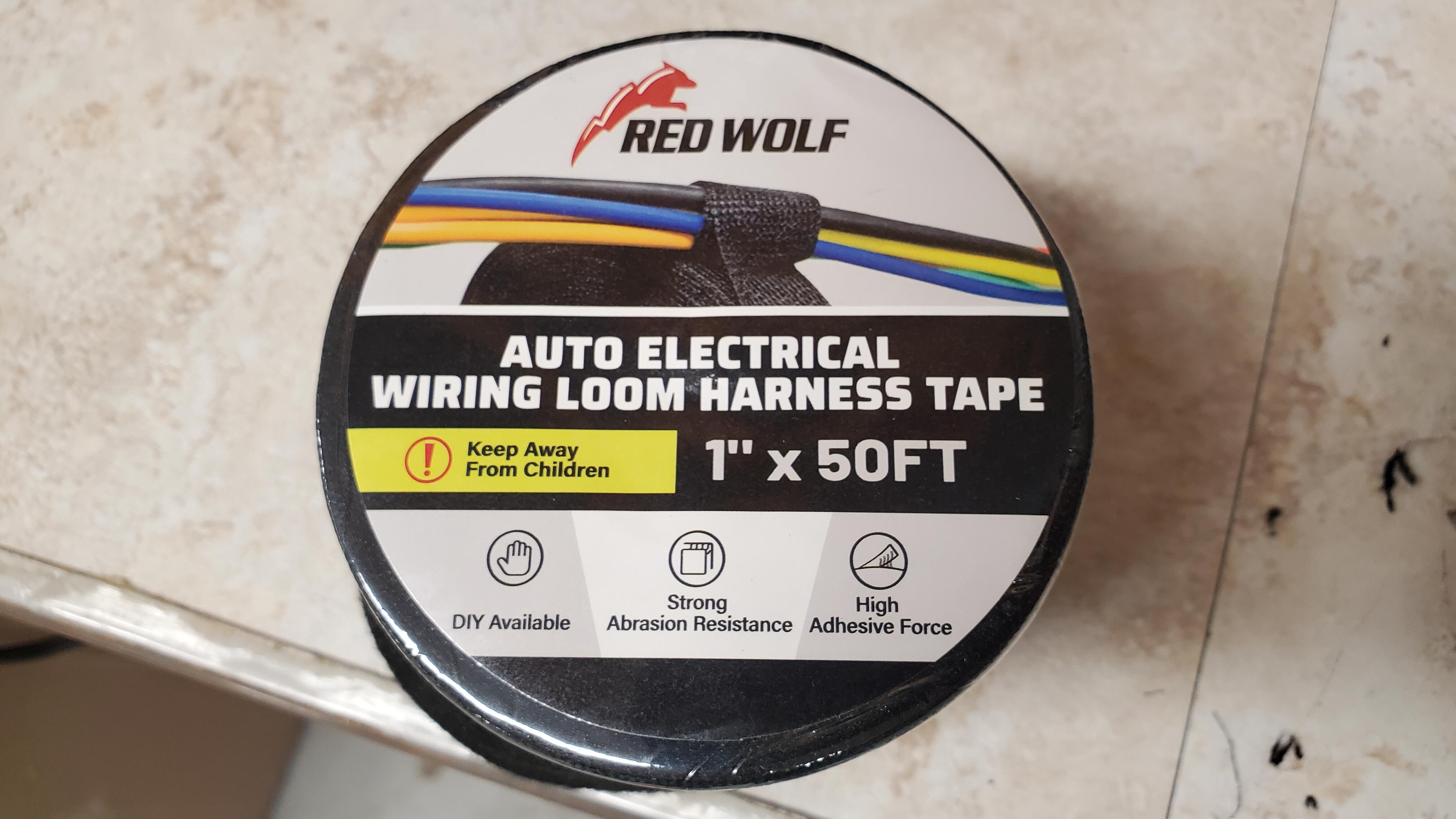
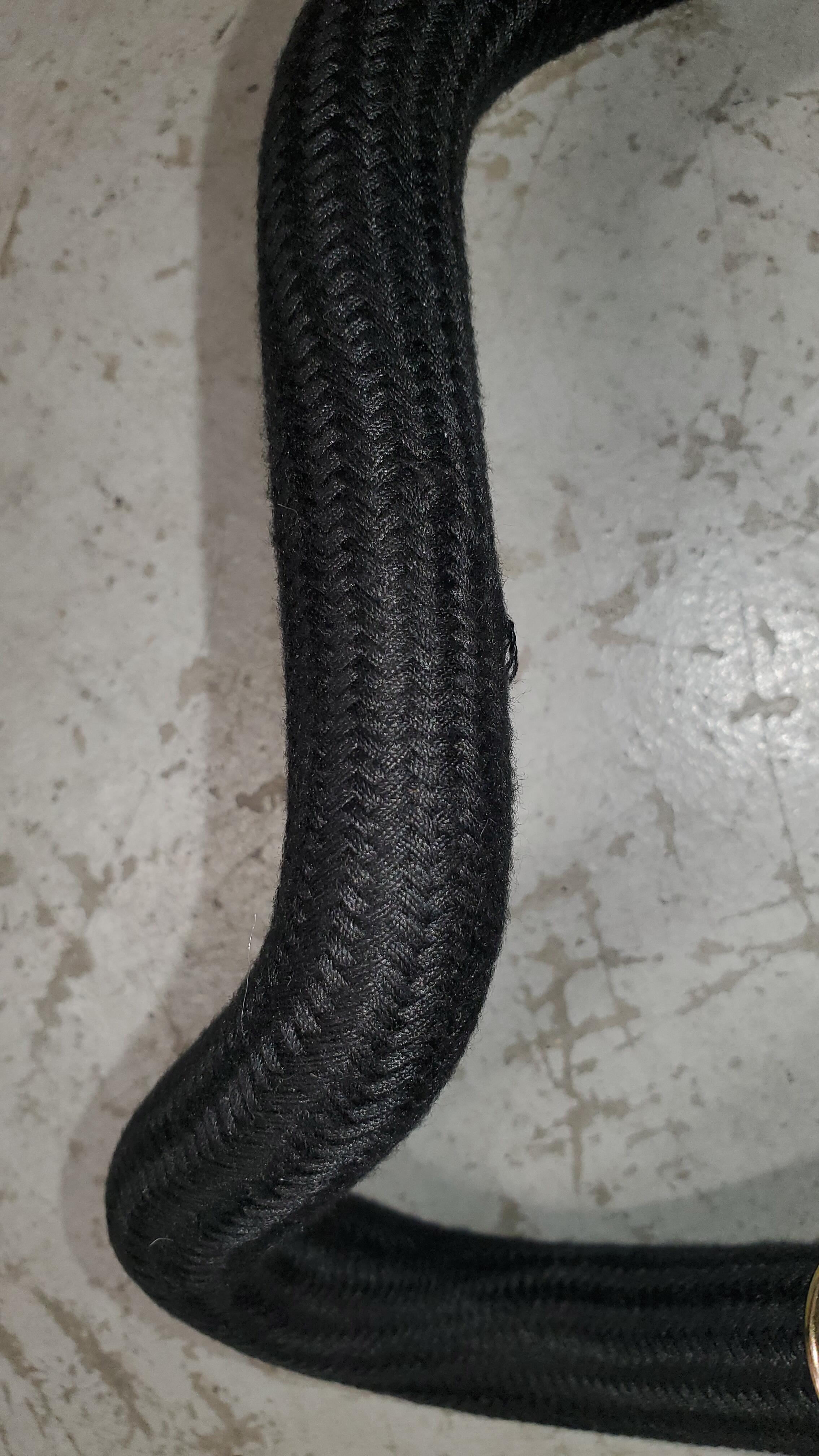
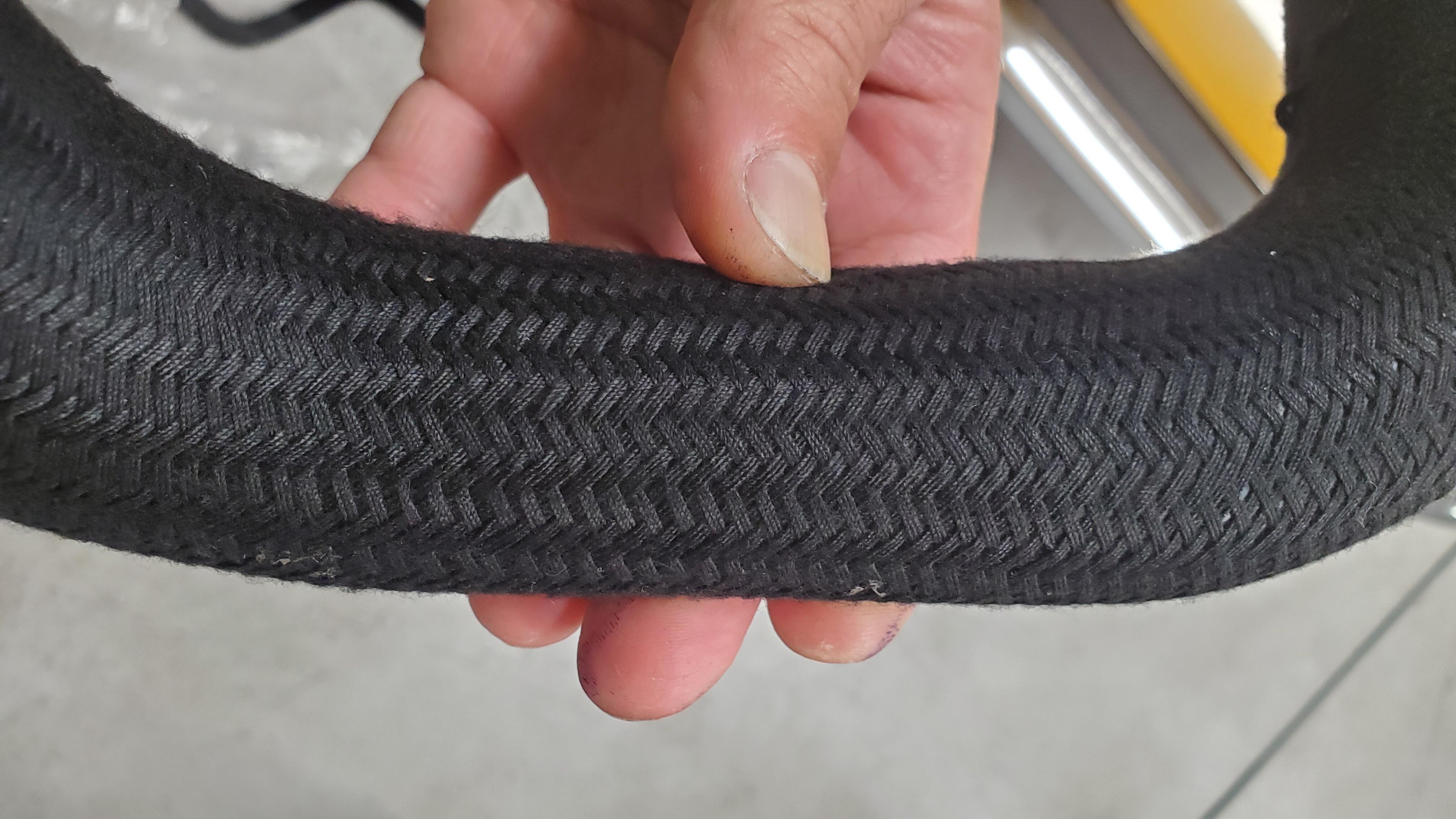
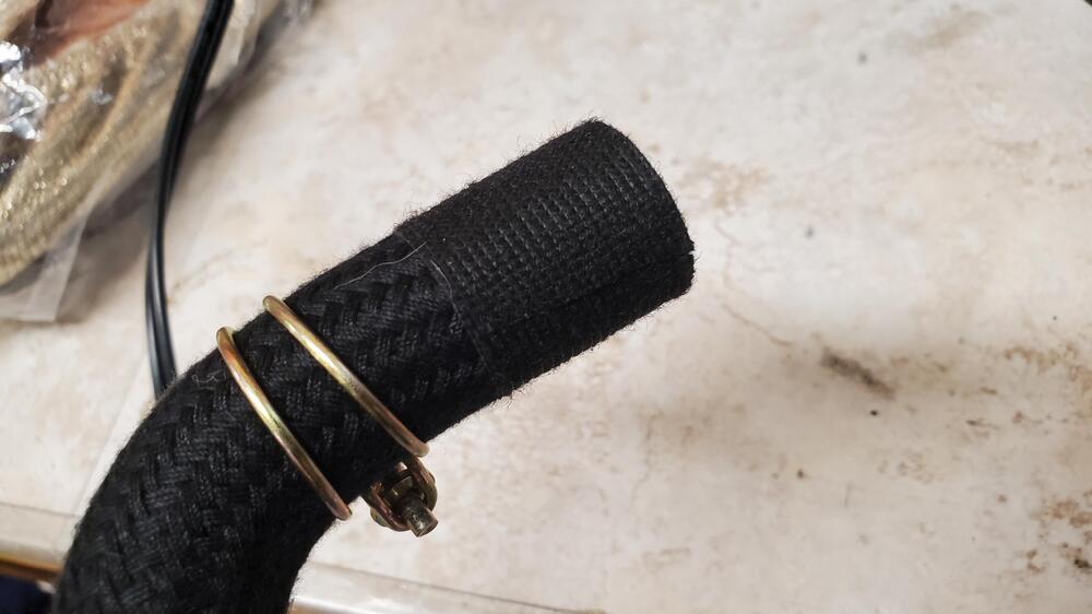
BTW, I started putting the resurrected hoses in today and a little trick for those that need it. Almost every braided hose I've come across has little "frays" on the end like this what i do is wrap the end in this cloth electrical tape once you put the tape around its really easy to trim those loose hairs with a standard scissor and you aren't struggling with the braids unwrapping while you do it. the color is a perfect match and once the clamps go on you cant even see it

-
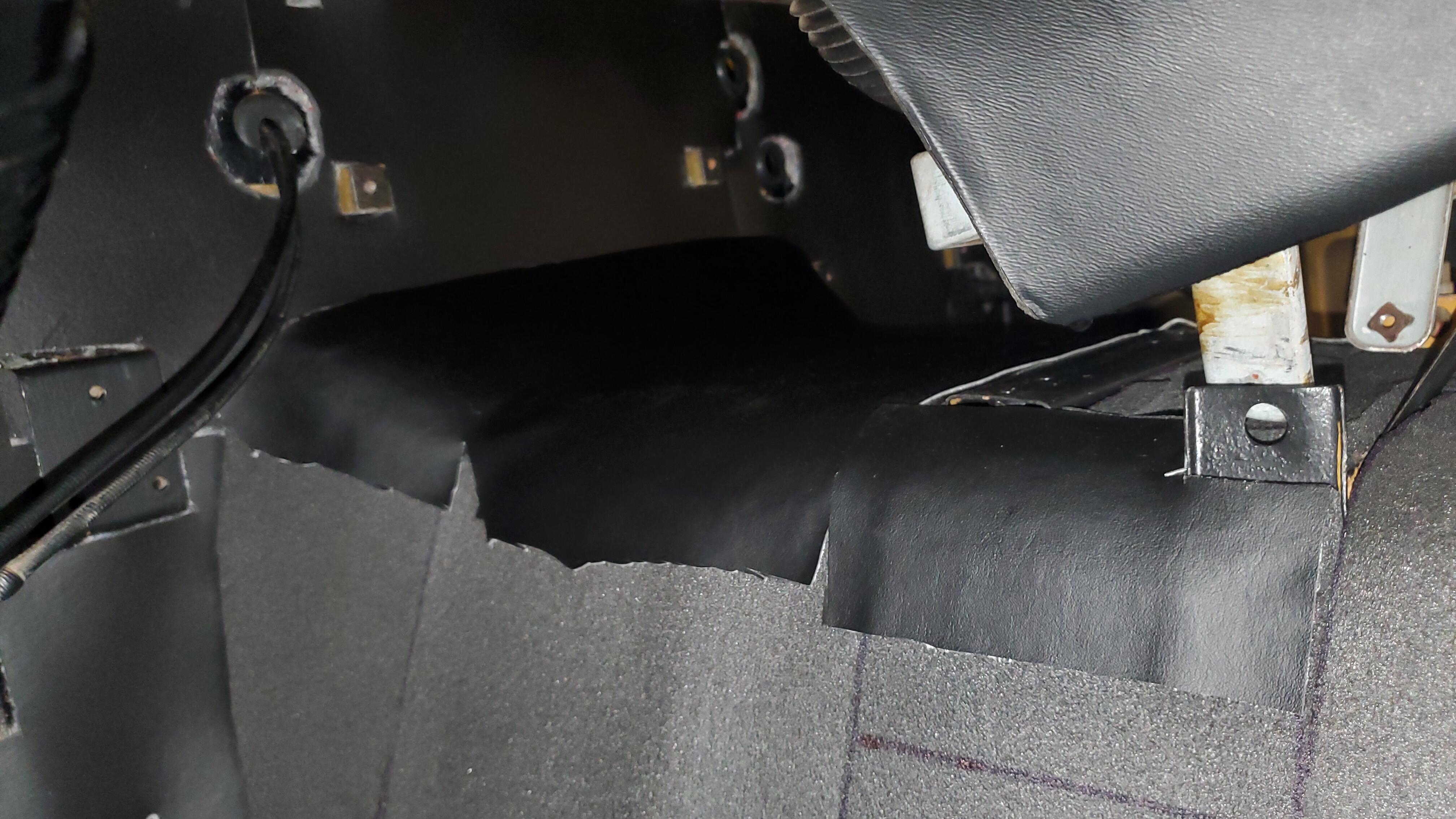
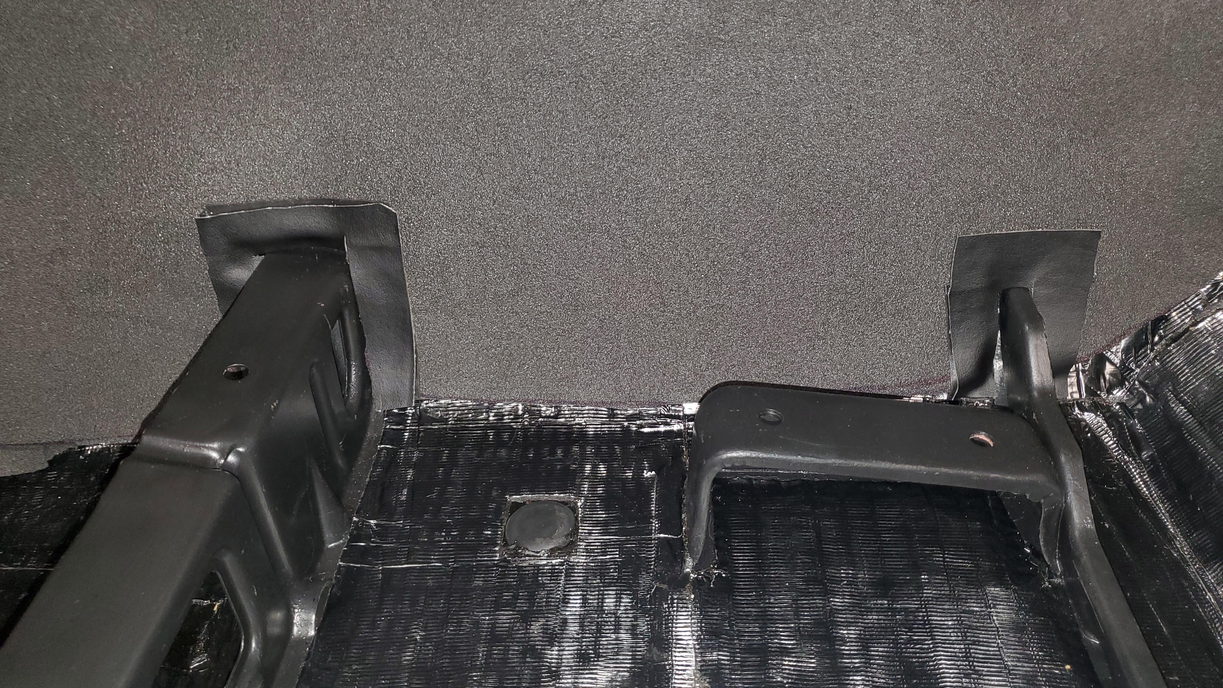
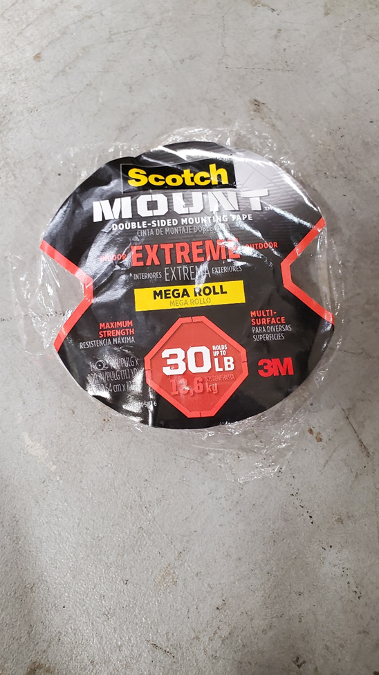
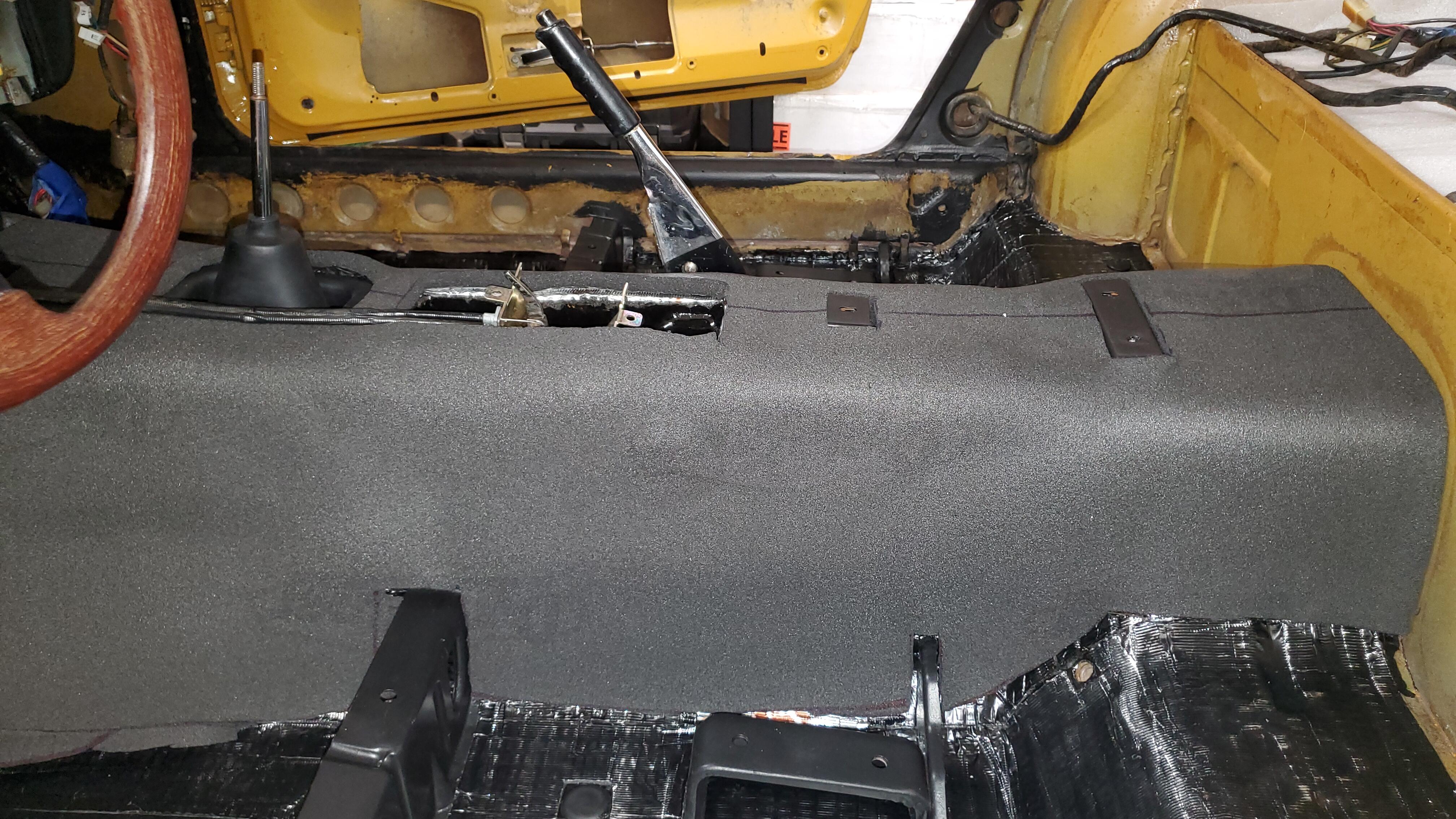
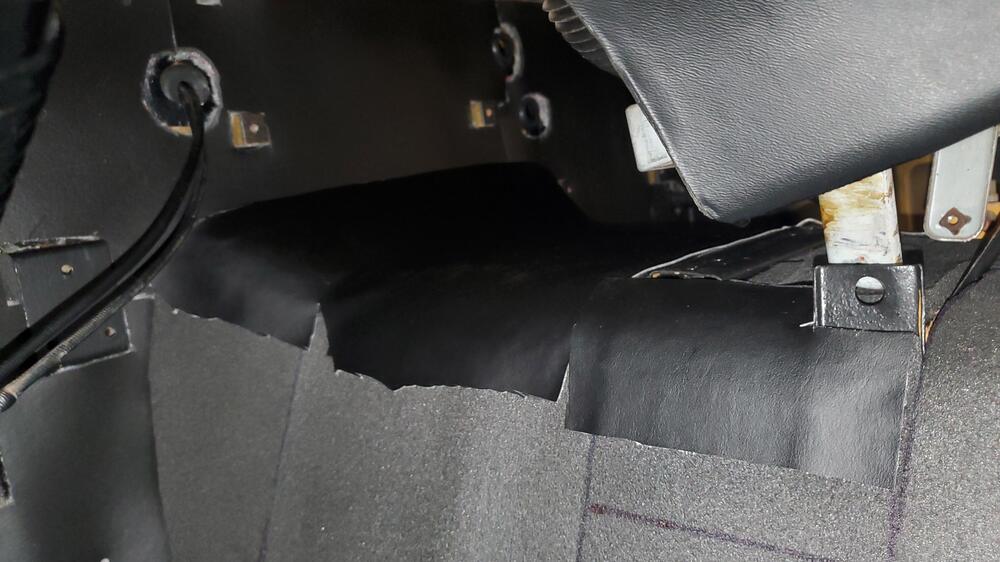
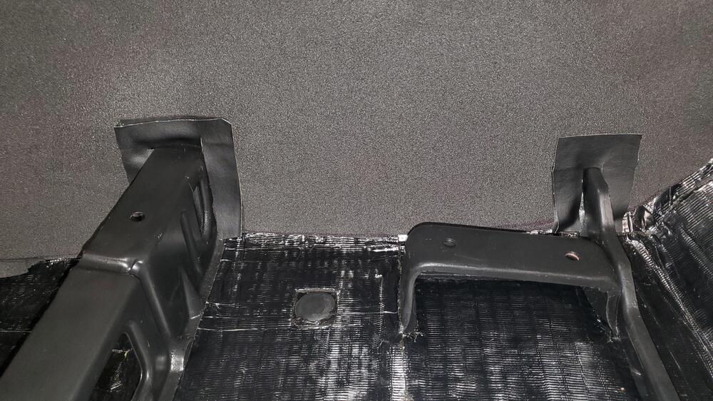
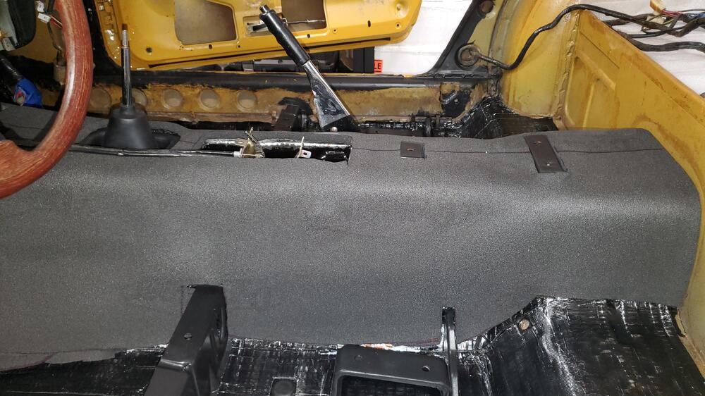
Update. I've started dry fitting the vinyl and noticed that the traditional cutouts for the seat rails and the typical pattern of slices near the firewall as it curves would expose some of the padding I just laid down. Didn't like that so took some of the old headliner I just replaced (so glad I kept the skin) and placed pieces to hide the grey padding once the vinyl is done. i used the same scotch tape from the headliner experiment and it works great. I'm using these pieces as a test run to see if this tape can be used for the actual vinyl itself rather than messy glue (just like i did the headliner). Here I did the entire under heater core box, looks great and the rails
- 1 reply
-
- 1
-

-
My two cents as a relative newbie to all this. i have a 6/71 build HLS3036219 and am not the original owner so i don't know what was original or not. By date and VIN it should be a pure series 2. the PO did a terrible job of restoring and took so many shortcuts its shameful. trying my best to correct all that I can. As i'm doing this I realize that the most important thing is to make your car what you want with it. I had to address seat mechanism issues and took the ebay route. Well what I did was get a 72 pair of seats which isn't correct for the car but its correct for me since I like the idea of the better reclining function. I also had to replace the fan, the original metal one was a mess well I decided to get the 72 plastic one to save wear and tear on the water pump, and the list could go on. So enjoy your cars, build and tinker to suit your needs. We wont be here forever so enjoy it.
-
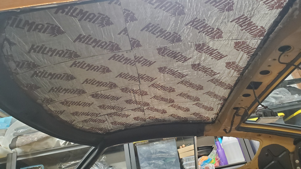
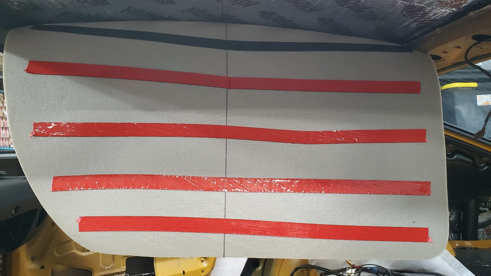
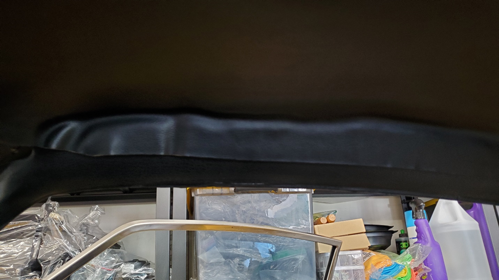
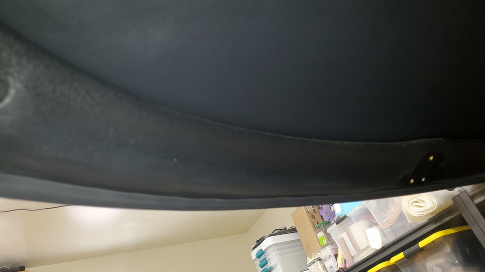
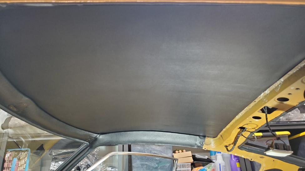
Things are coming together quicker than expected and I got to the headliner today. I had purchased one from the z store almost two years ago but was severely delayed with the project. It came with the typical spray on glue but before IO went to tackle this i had a moment of hesitation. I still have the dash in the car and the thought of over spray and drippings of that glue (its 104 today in Roseville) really had me pause. I was thinking about the recent dynaliner experience with the peel off backing and thought why not do the same for the headliner. So I went to the home depot near me and after looking around decided on this since it was the stickiest, had a high temp resistance, and was relatively thin compared to others of the same strength a single roll ended up covering the entire liner in strips from front to back about 3 in apart. I made sure not to get too close to the ends on all 4 sides since I knew I had to tuck under the edges. TIP - Make sure to draw center lines in both directions and place some painters tape on the vinyl side to match so you can see the tape when attempting to stick to the ceiling. This allows for easy orientation with the center of the mirror mount and the lamp light cutout. I started with by doing the soundproof (highly recommend, the roof now is like a modern car After laying out the tape on the back of the pad I used the same 1 inch roller that I pressed down the soundproof to really press down the tape onto the back of the liner. I made sure it wouldn’t peel up without some real tugging. Once I was happy I pulled the red backing from the center line only and attached it to the roof right down the center line using the painters tape as guides I then worked on the passenger side first removing all red backing and carefully working from center towards door fram pressing the liner up onto the ceiling. Was very happy with how smooth and easy it was and did the driver to match. When I was done I had about 2 inch of material exposed on the doors frames and an inch or so on front and back. TIP – DO NOT BE TEMPTED TO TRIM, it will all fit with gentle tucking The front is the most visible so I decided to start dead center with a tool for scraping glue from windows I was surprised how easily it tucked under the front and went from center to edge in both directions in maybe 45 secs I then went down each side to the turn at the back and finally across the back. Finished product looks factory new! Time will tell if I took an easy way out and this droops from heat or deterioration of the pad but I feel it was the right thing to do considering my circumstances and doing the least amount of harm to the dash 😊 Total install was less than 20 mins, way faster and less messy than spray or roll on adhesive in my opinion.

-
Datsun 240Z Braided Heater hose set available
Richie G replied to esprist's topic in Open Discussions
Here's some of the coolant and heater hoses from resurrected.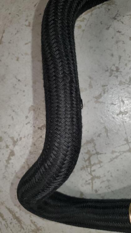

-
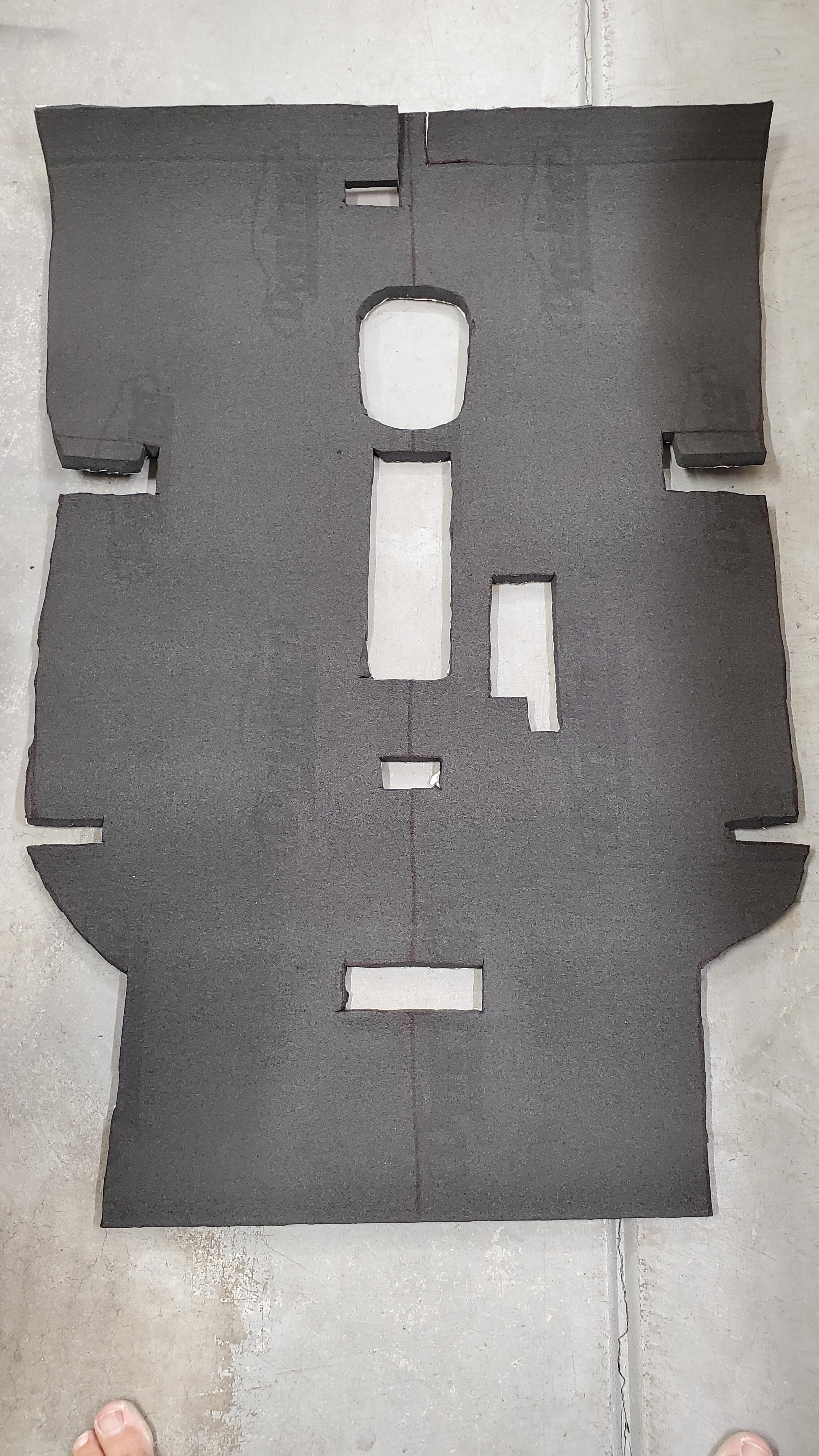
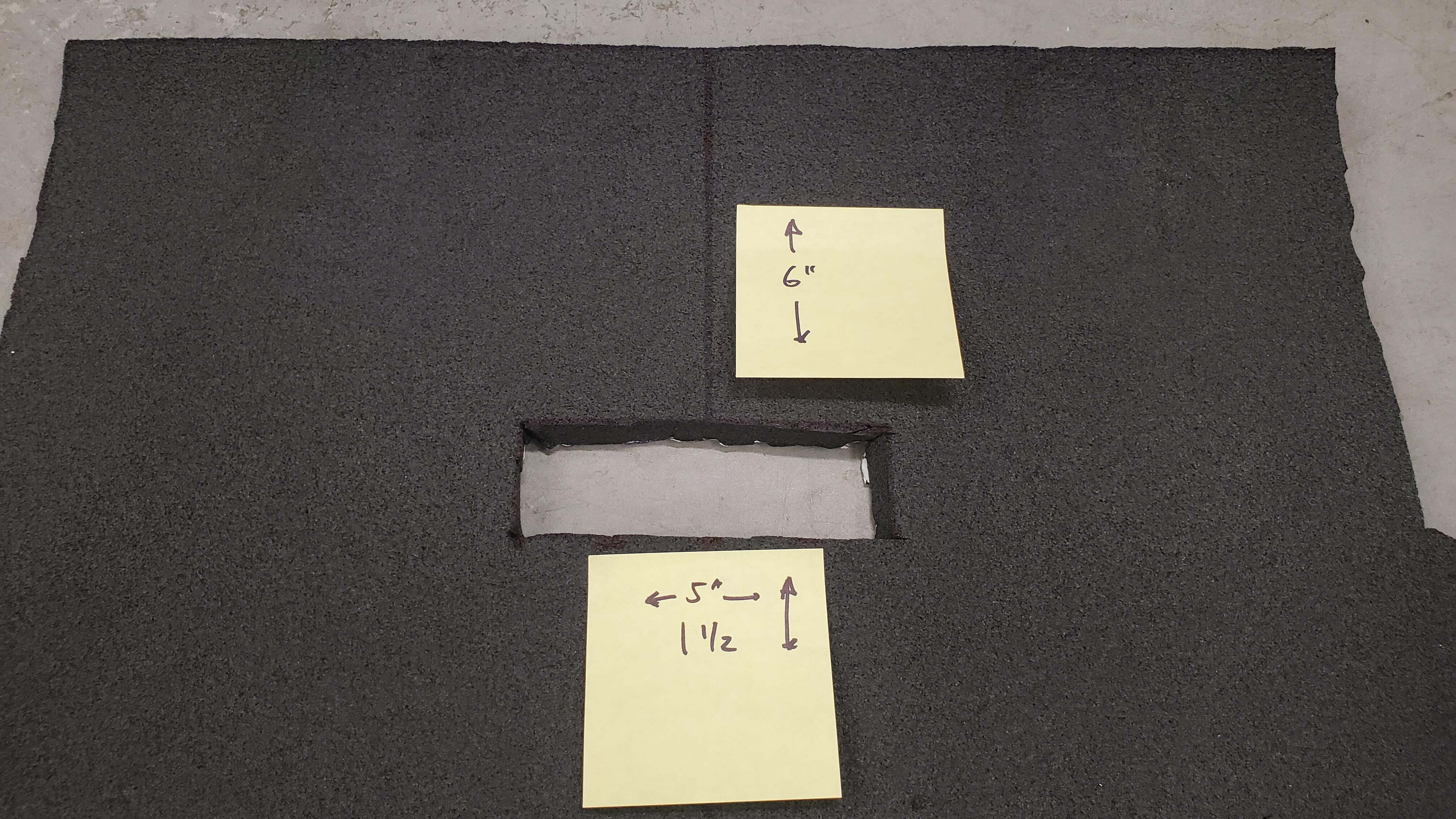
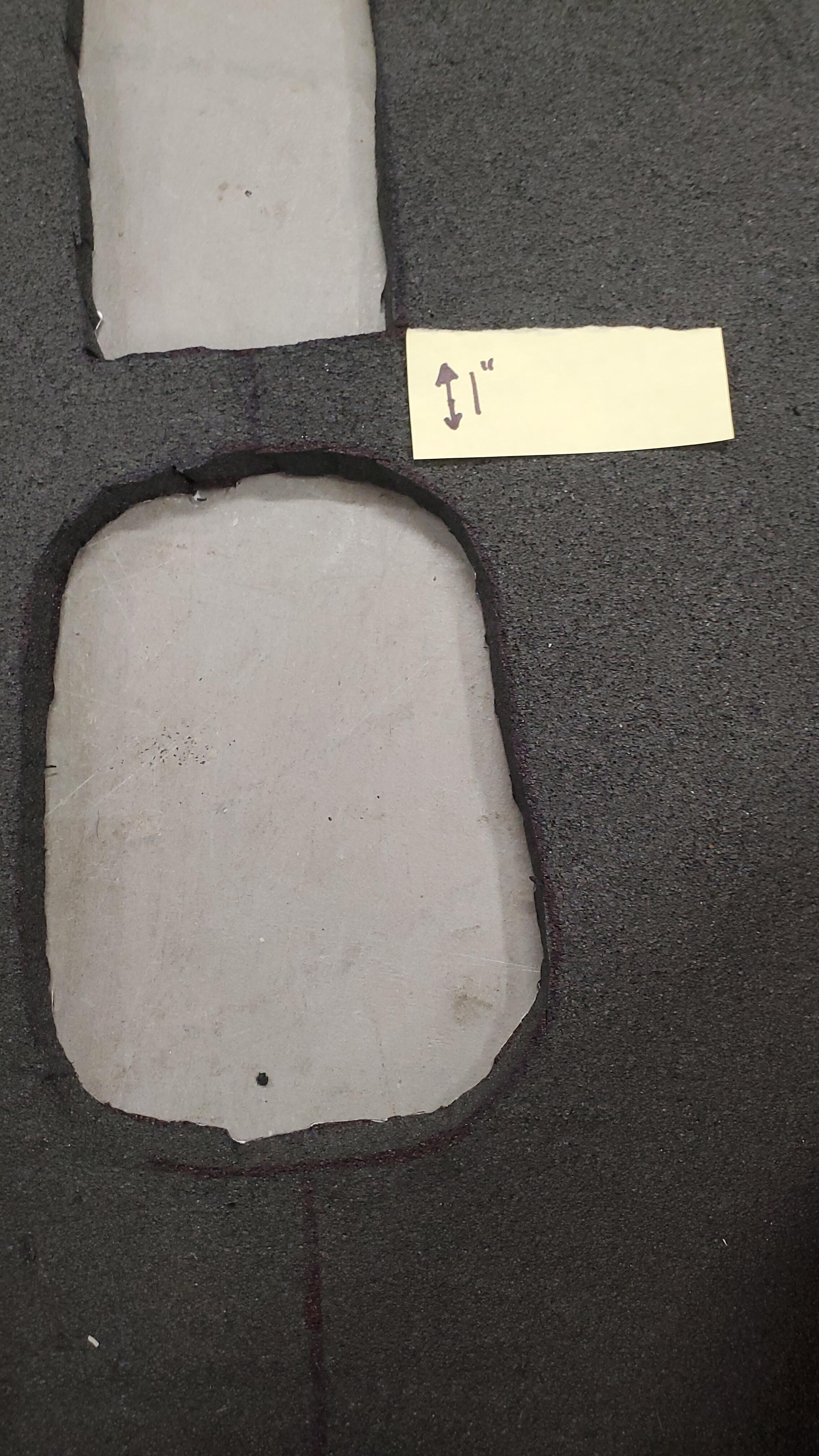
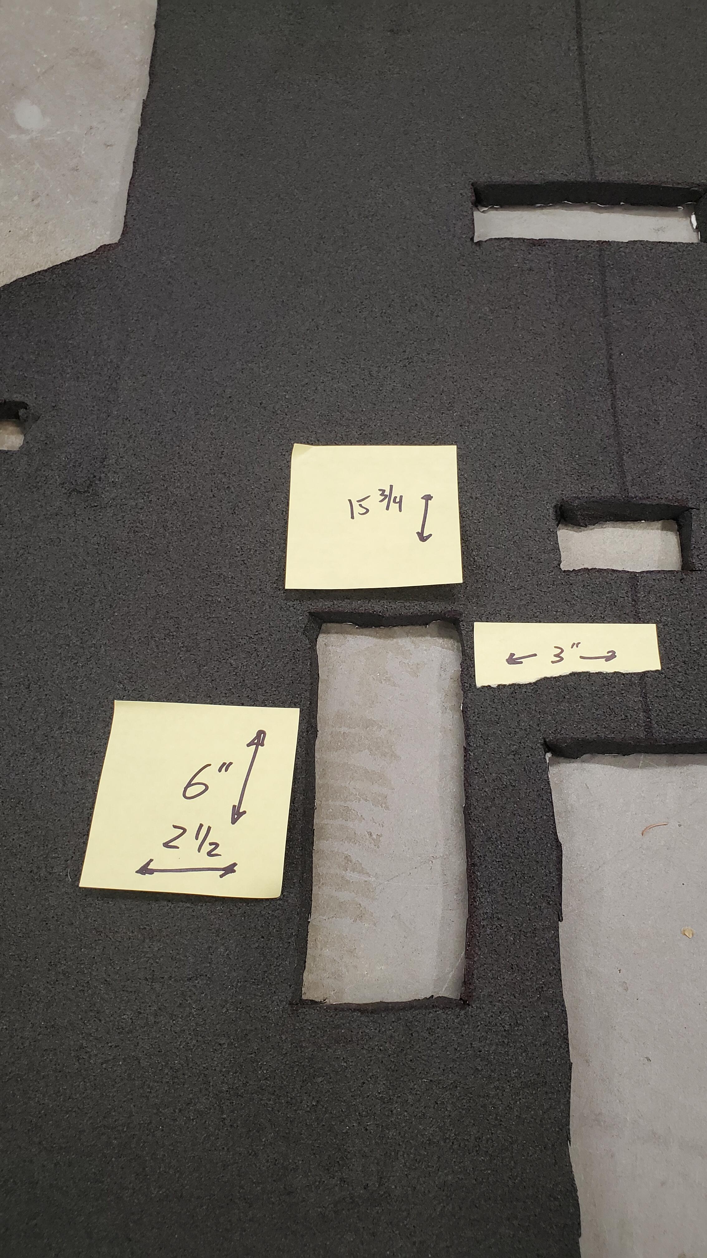
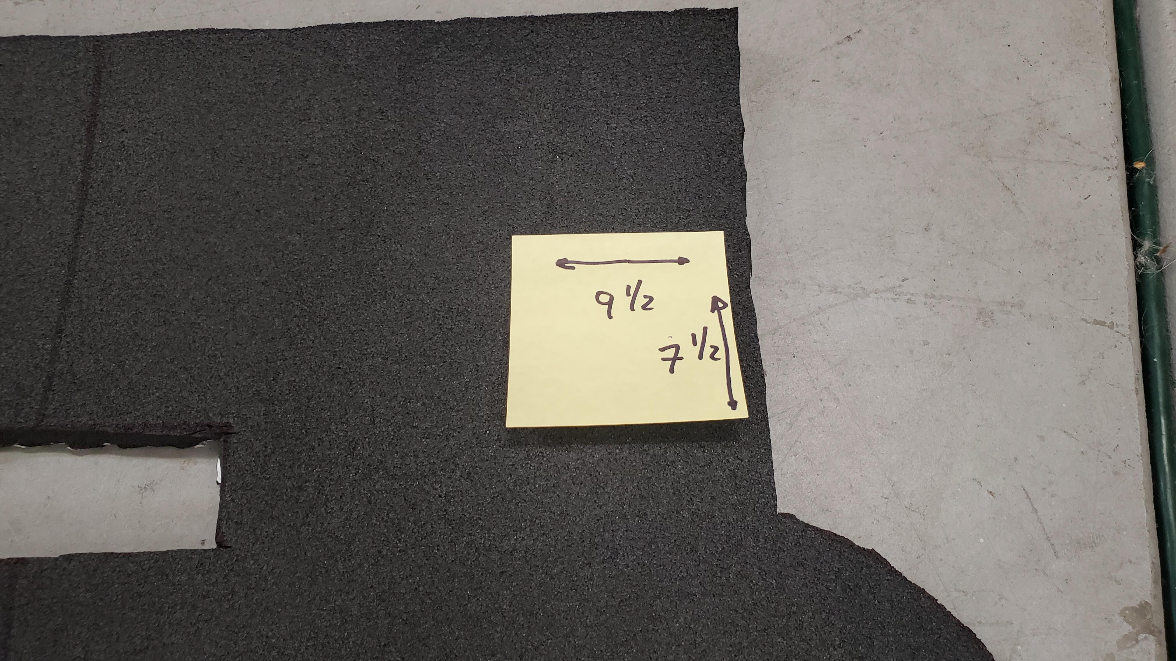
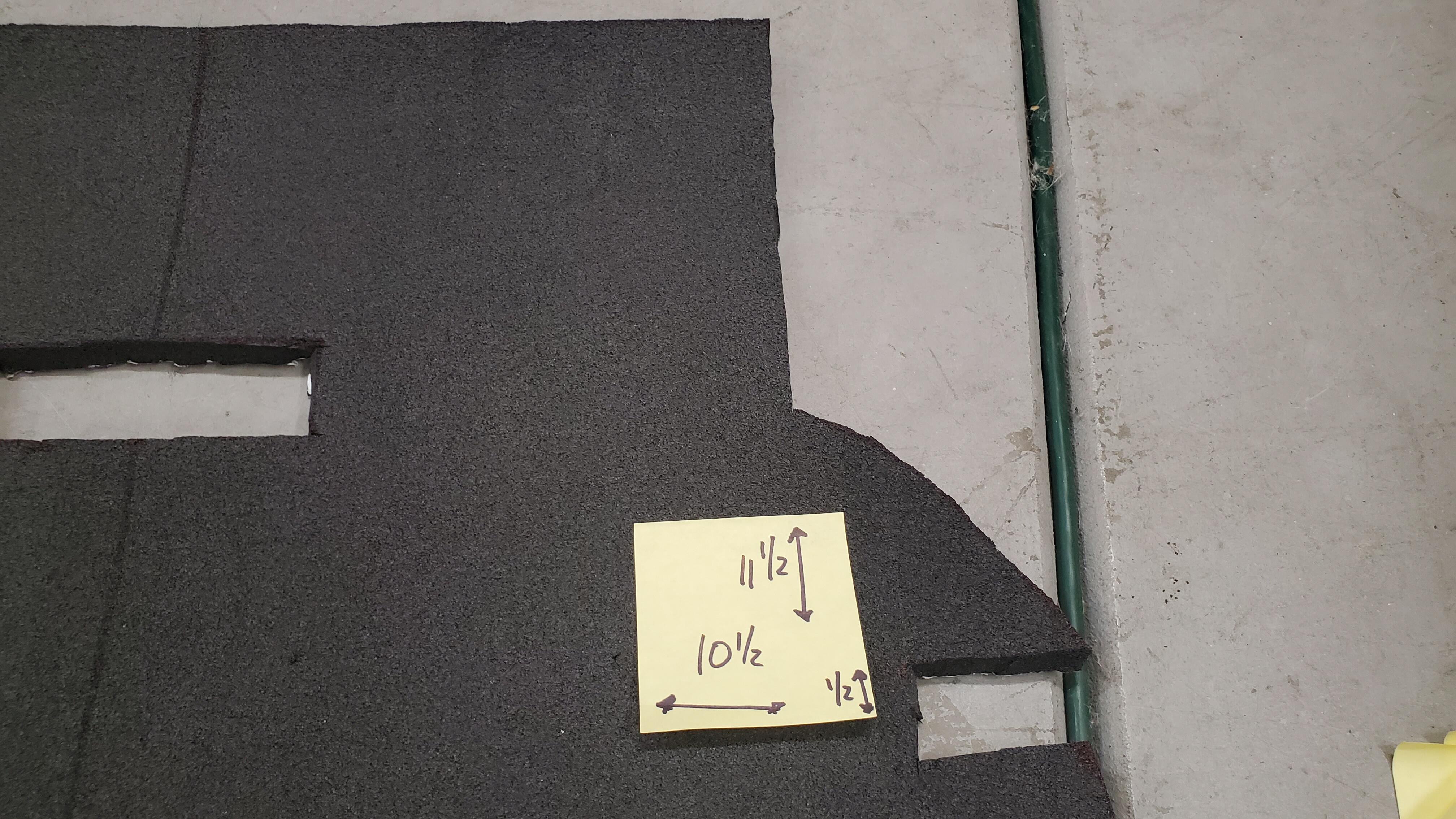
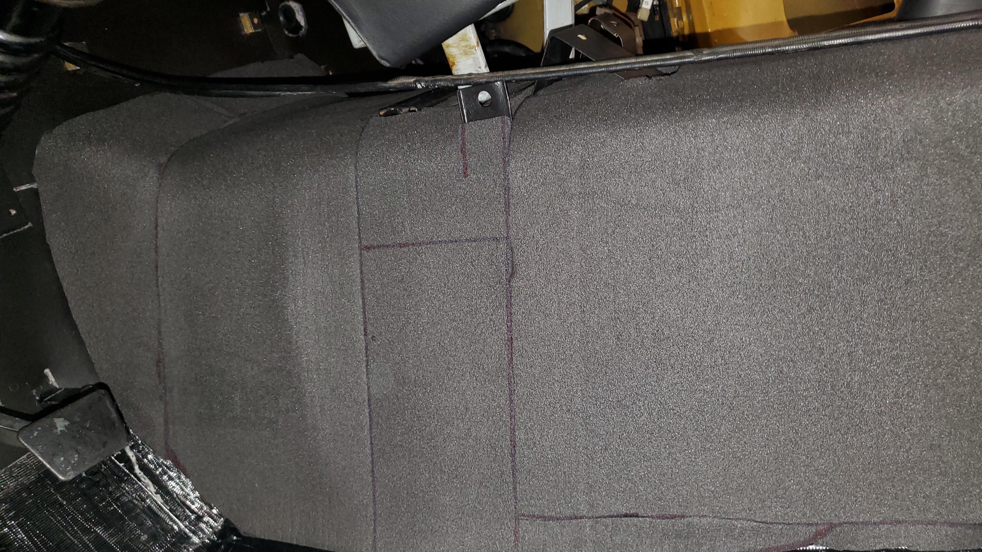
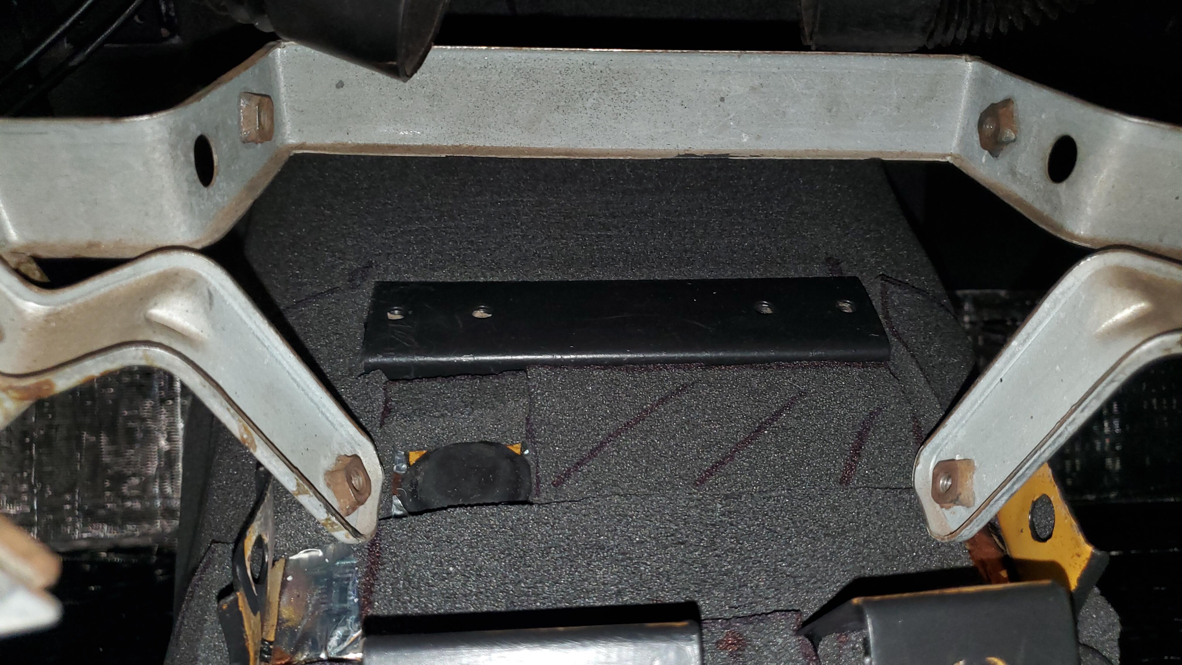
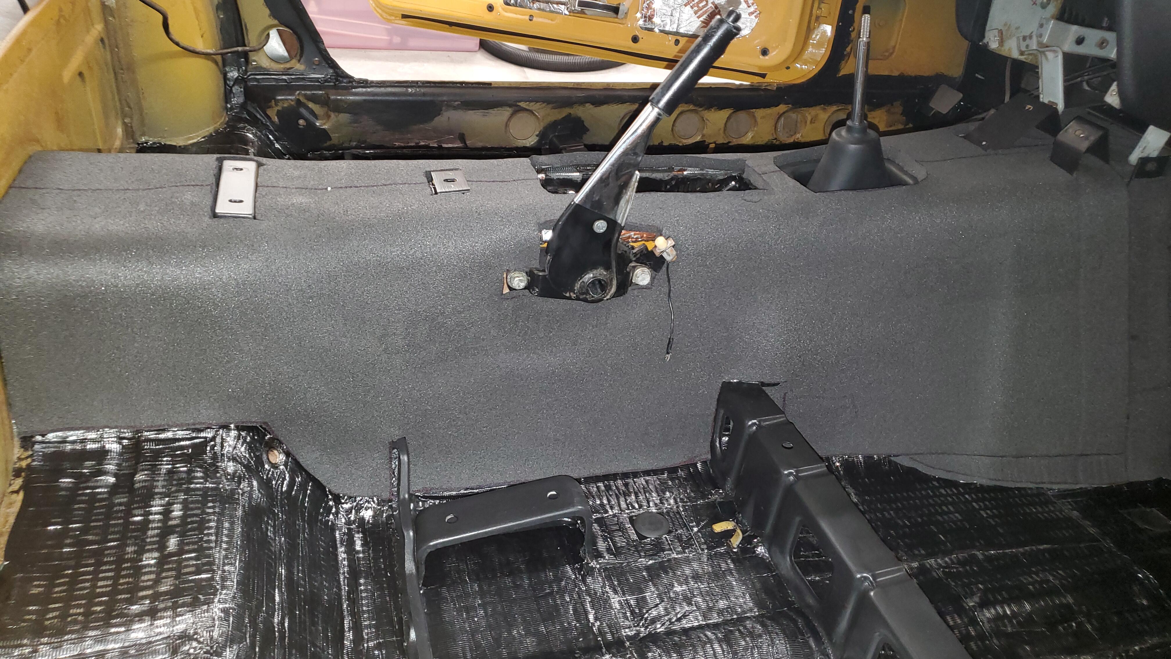
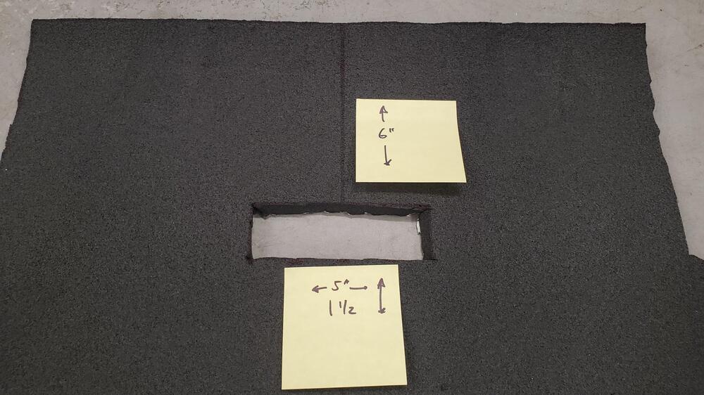
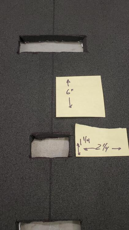
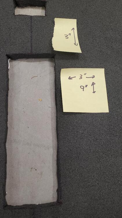
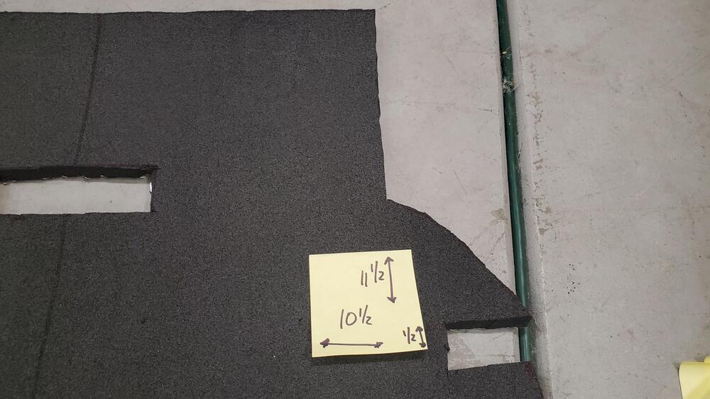
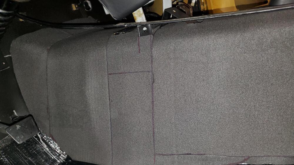
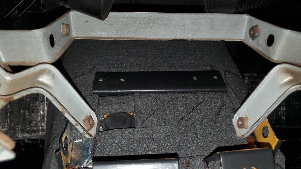
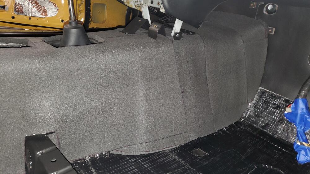
I'm at that point that i needed to put back the insulation after restoring floorboards and sound deadening. I had done my research on here and found excellent material with large printer format templates for the cutouts but I didn't have a printer to do it on. So I did it the old fashioned way with cutout by cutout tailor like approach. i made measurements along the way if its helpful for anyone without the ability to use autocad or a large printer. I decided to start with the dynaliner material i had seen on here a few years ago when I was ripping the old matted disgusting wool pad out. This stuff seemed easy with stick on backing and a great smooth surface for the eventual spray on headliner cement for the vinyl . Here it is if anyone hasn't seen it on amazon https://www.amazon.com/Dynamat-11103-Dynaliner-Self-Adhesive-Deadener/dp/B001JT5NIU/ref=asc_df_B001JT5NIU?tag=bingshoppinga-20&linkCode=df0&hvadid=79989522876749&hvnetw=o&hvqmt=e&hvbmt=be&hvdev=c&hvlocint=&hvlocphy=&hvtargid=pla-4583589102084678&psc=1 If you layout the piece you get its pretty close to the exact full length of the tunnel from firewall to rear tunnel at the hatch. (I have an early 71 btw, maybe a slightly different length for the series 1?). Now I do have to admit, this probably would have been easier if i took the dash out, but i decided to do it in a few smaller sections instead to avoid that. My first step was to do a full single piece from the hatch to the dash mounts on the tunnel. Like many others, i started with a center line to help orient things. My measurements ended up being 42 1/2 " from those mounts to the hatch so I cut that first section out of the full piece leaving the full width. Here's the final with cutouts and I'll get to the dimensions of each in a minute Oh and I see you get some bonus toes thrown in for good measure! I then laid the piece out with the center line down the tunnel and made my first cut for the console mounts by measuring from the back of the piece forward. it was 6 in exactly and the rectangle was 5x1.5 then to the other mount measured from the first cut to the next, again exactly 6" and 2.25/1.25 then to the choke location, same method from previous cut to new cut 3" and 3x9 the last easy center line cut was only an 1" and I used the inner shift boot as a template next cutout for the brake was a little different since it was off center. i took measurements from the rear as 15.75 and from centerline as 3" making a rectangular cut 6x2.5 that was all the difficult ones and the pad fit near perfectly which had me very pleased. What i did next was to start by measuring the back section of the tunnel which was the shortest and easiest to cut, again measuring from rear and centerline to the "curve" where the tuinnel meets the raised floor behind the seats. IMPORTANT TRICK, use painters tapoe when measuring curved surfaces then just layout the tape on the pad and slice. My measurements were 9.5 from center and 7.5 from rear to the point where the floor starts to curve. the other side was symmetrical so i did the same all that was left were seat rails, again measuring everything from the rear and center line on the pad rear rail was 11.5 from rear and 10.5 from center with a narrow .5 slit front rail again from rear of mat was 25 from rear and 9.5 from center with again .5" slit but in the shape of an L (sorry no pic) Again both sides symmetrical so did the same on the other side last step was to place it on the tunnel and then just follow the contour of the floor to trim as needed and to trim around the fuse and lighter mounts. IMPORTANT TIP Make sure to fit not once but twice everything dry wiothout removing the backing until you have it just right Once this piece is in you'll have the hang of this and all the tough parts are done, the rest is to use the scraps to fill in the easy parts under the dash. most of these are square and you can use the painter tap trick to get exact lengths. make sure to leave enough overlay at the bottom and just trim to what you need. Some shots of final product ready for vinyl I'll probably have to trim around the fuse box and lighter mounts, maybe even under the radio before i put it all back but i wanted to cover everything i could and work backwards as needed rather than try to add little pieces after those instalations. Not concourse, not perfect, nothing magical but hopefully helpful for someone. BTW, the single piece of dynaliner may run you a little short, I think i may have used some scraps from a previous piece i had for something else. I cant tell since all the scraps ended up in one pile where they were coming from but its real darn close if you are economical with your cuts.


- 1 reply
-
- 4
-
-
Video recommendation: "My Mechanics" restores a 240Z
Richie G replied to florian's topic in Open Discussions
amazing work. the tape peeling at the end gave me goose bumps lol, so satisfying to watch the sand blasting. very ASMR type feel to it. -
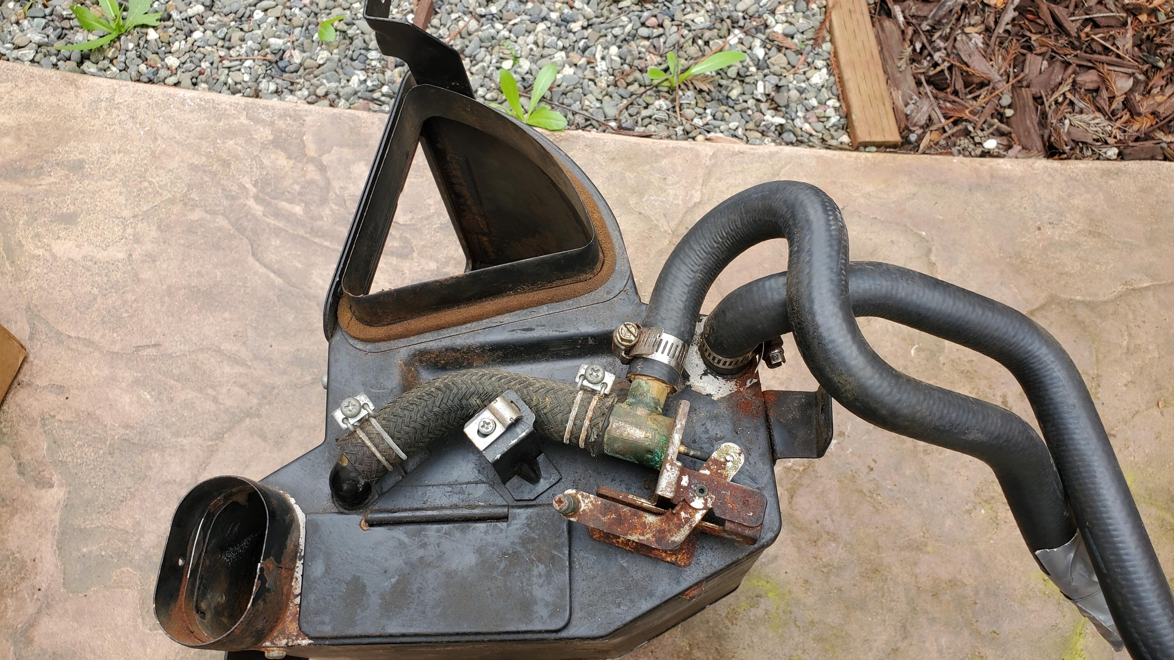
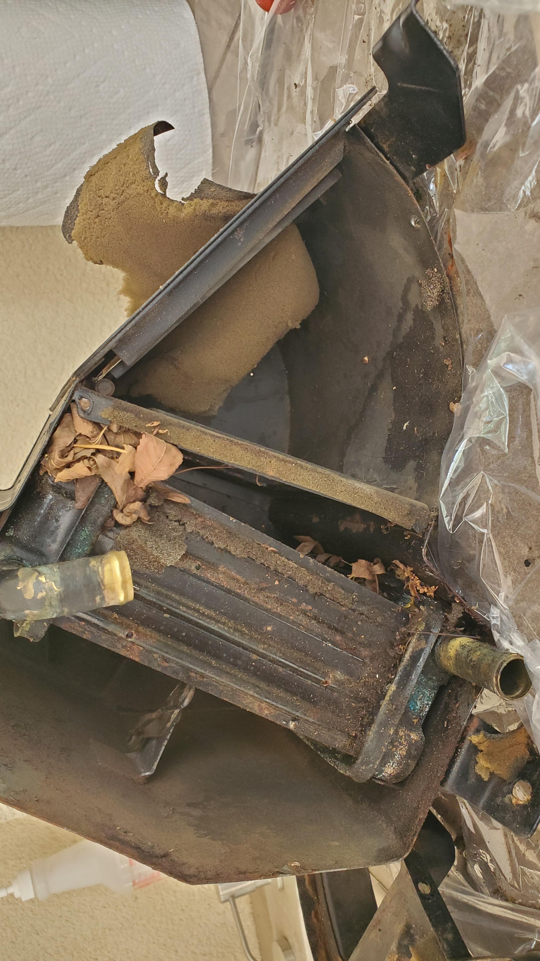
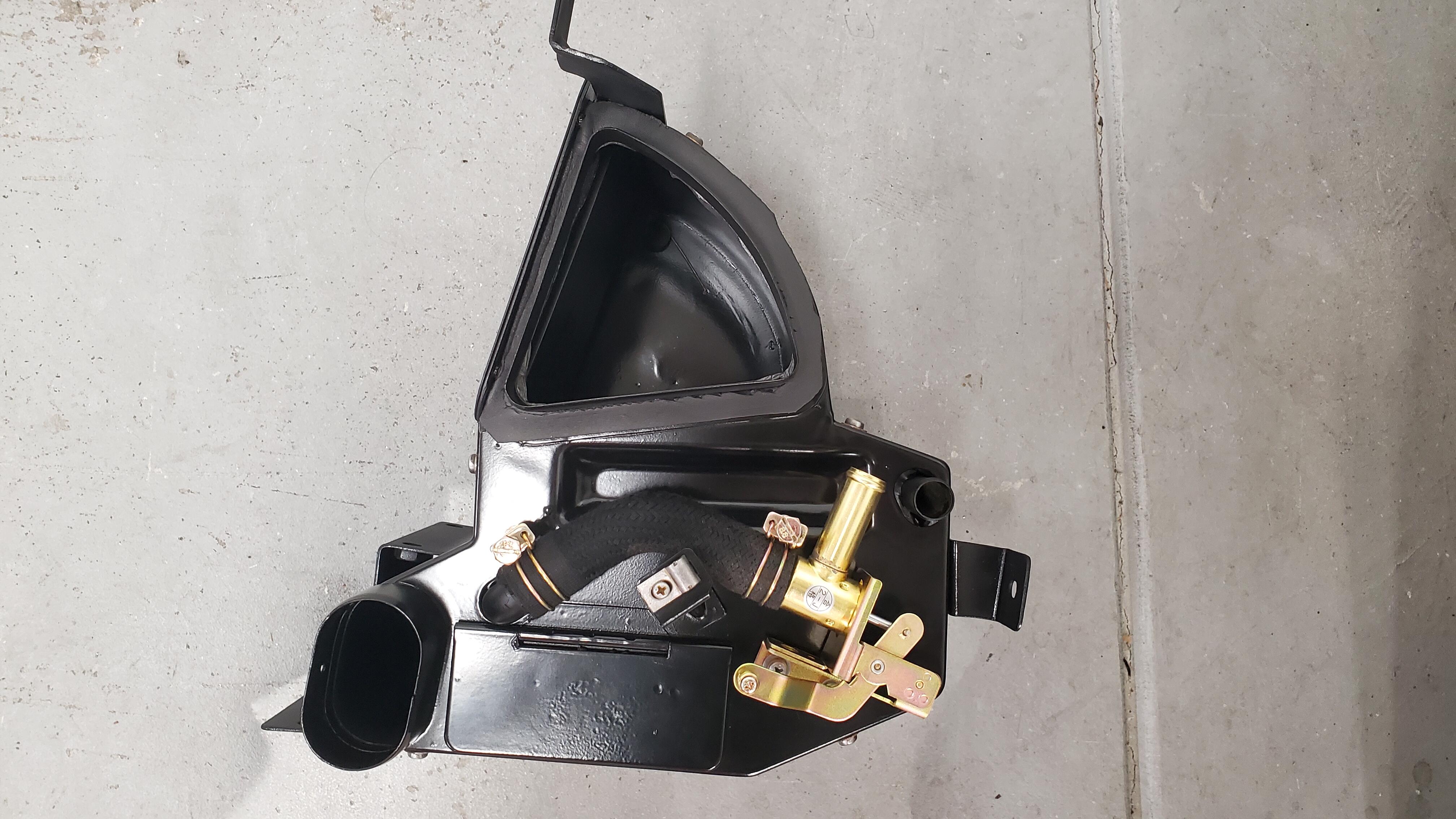
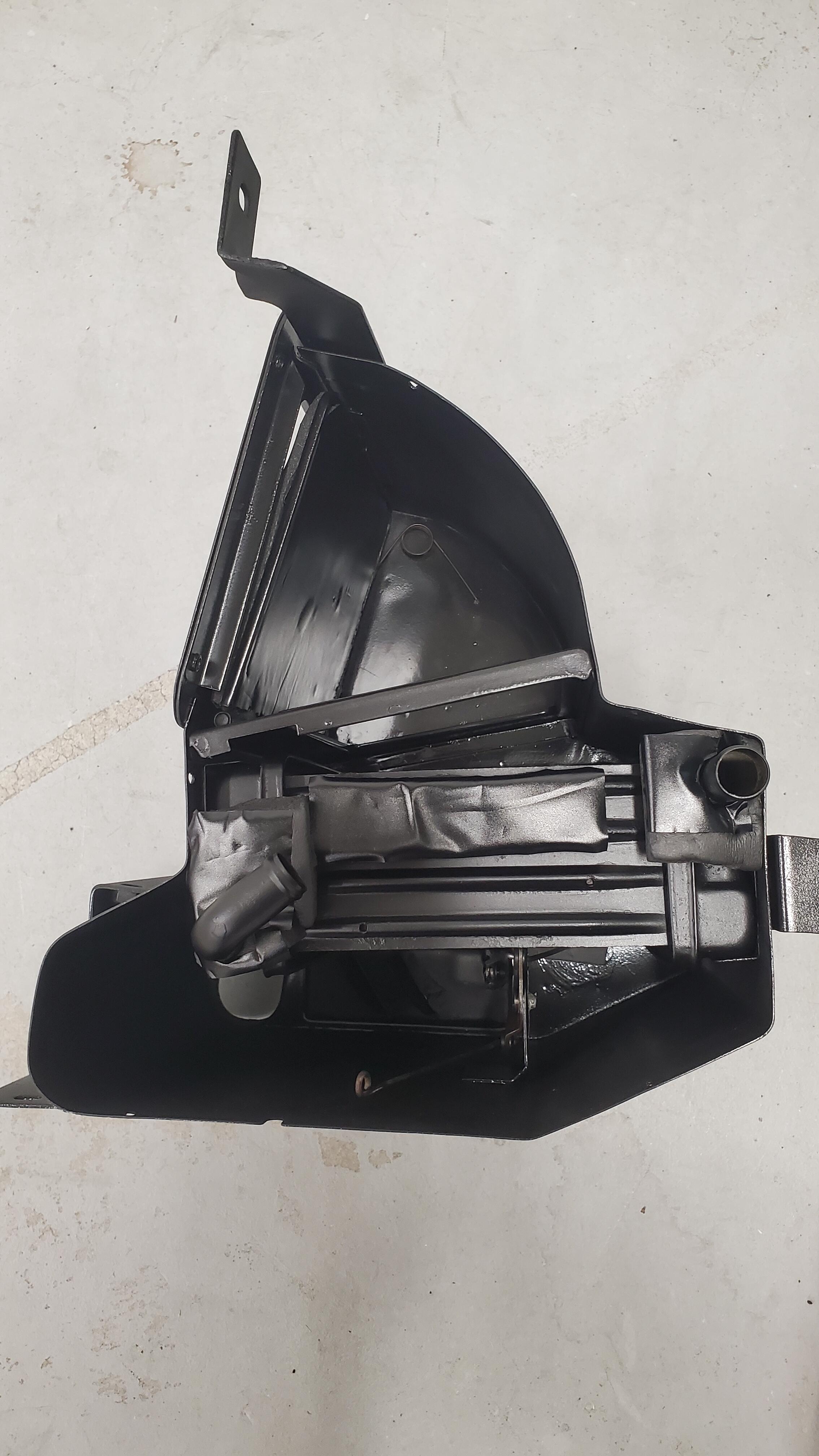
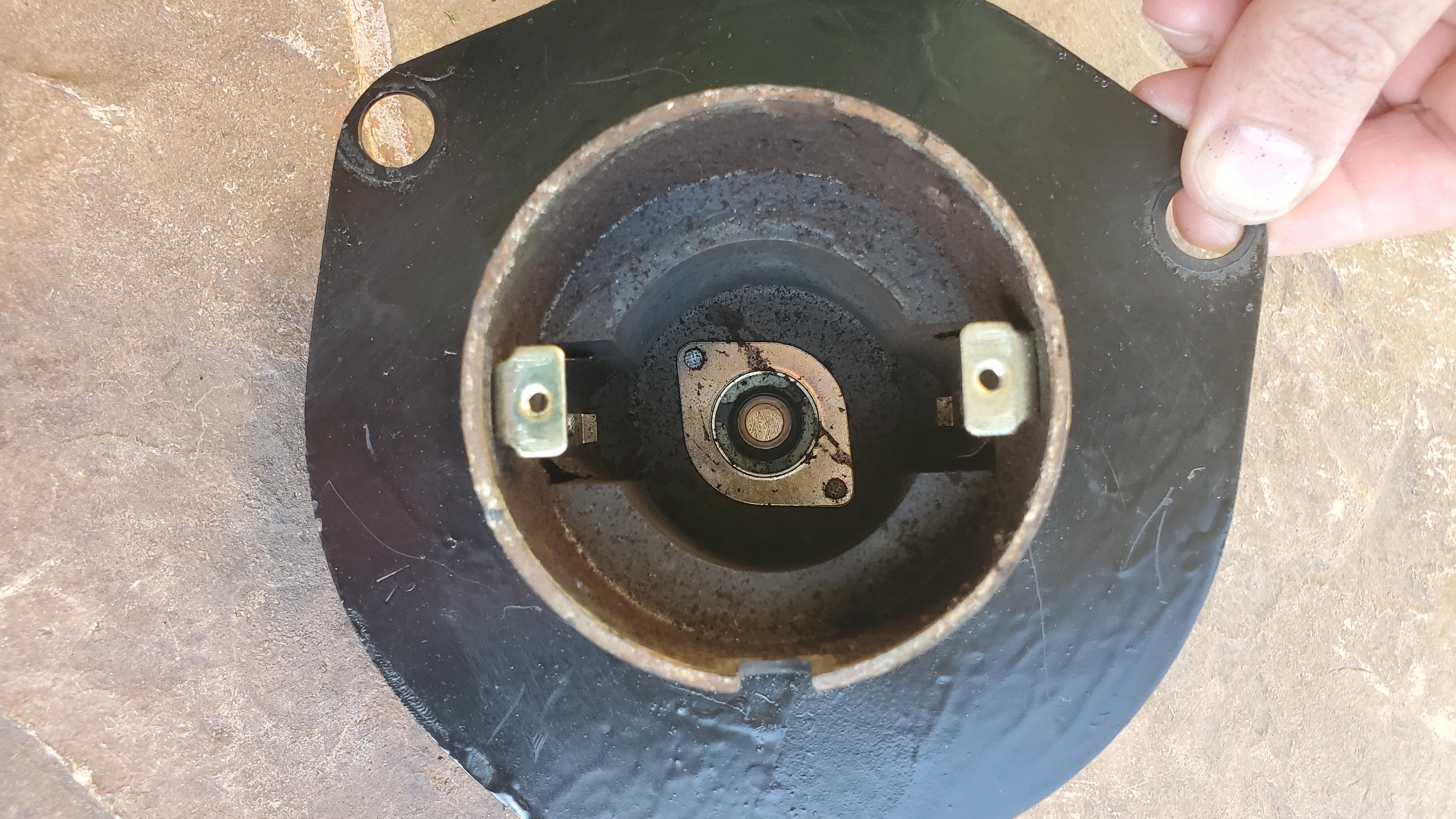
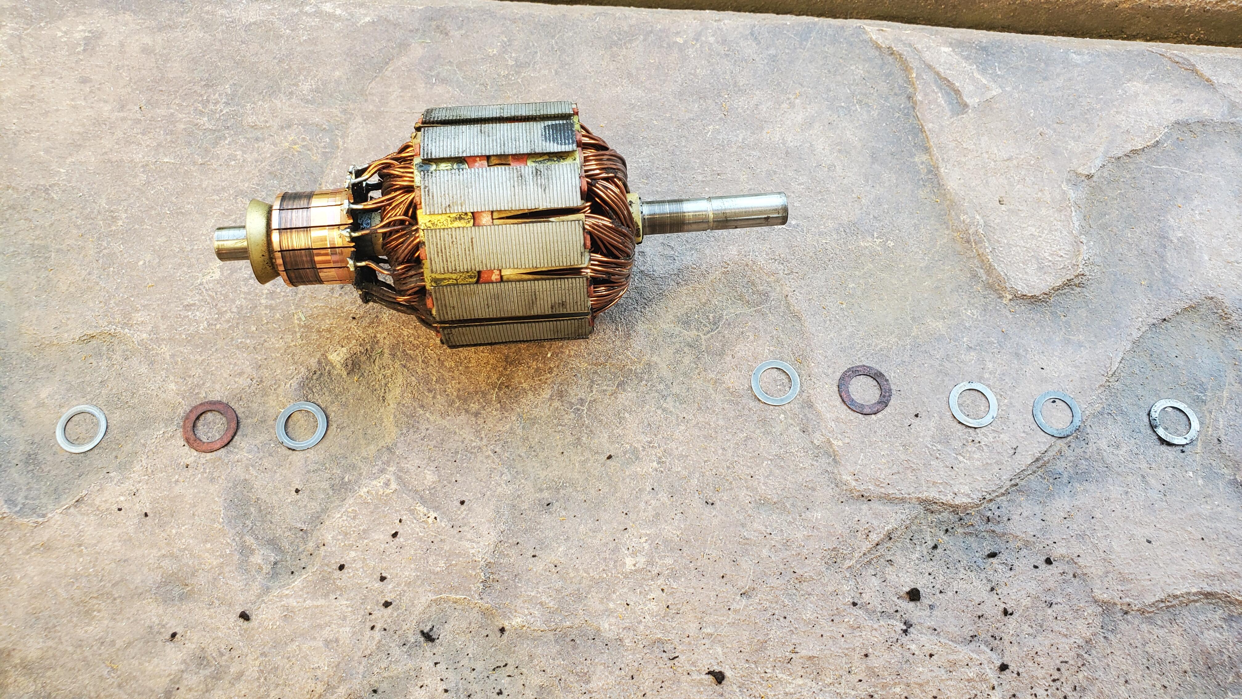
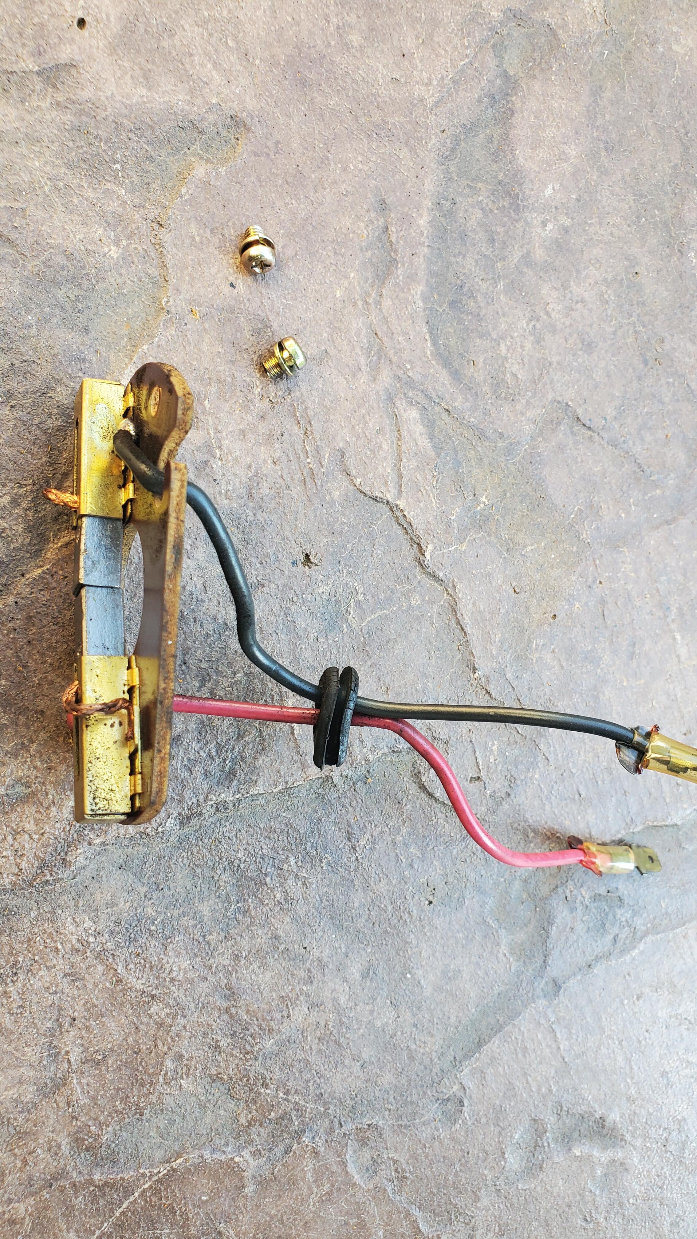
Now that Ive completed the core and heater box I'm moving on to the blower motor and fresh air box. Have a question about the motor but before i get there I want to first acknowledge @Namerow because I couldnt have gotten anywhere near as good as it came out without the help here. truly a great post and for a newbie like me as simple as i could have hoped. Before After Now on to the motor. The previous owner dumped paint on everything like it was a chocolate sunday it seems trying to cover anything they didnt want to address before selling. the motor housing is a mess so I need to repaint that and the box looks pretty much like the heater box did so that needs new gaskets and paint as well. Now that I have it disassembled, the inside of the housing has a thick layer of soot and grime in there surrounding the magnets. and the wire spool seems to be in great shape but also had a bunch of dirt and dust fall out of it when i took it out the switch was in great shape with the springs having good tension and surprisingly the screws look like they must have on day 1 at the factory I mean really, look at those. Its like I just bought them for 20 bucks from Zeddsaver LOL! So here's the question in all this. Is it Ok to use a degreaser on the electric coils and the inner housing where the magnets are? I've been using it all along as a first step in all these restos. Typically spray on, let sit a bit but not to full dryness, wash off with clean water to neutralize and remove. then on to sanding painting etc. If I do this to clean the inner housing and coils any issue? And I guess I apply some grease to the axle before reassembly? This all worked well before I took it out almost 18 months ago so it should all still be fine.


-
Found one for a couple of bucks! Went to Junkyard Jenny, she pretty much has anything you could every need and her prices are incredibly reasonable. She even sand blasts and strip things as needed to make them pretty much straight from package to car. If anyone ever needs anything from her just email her, she has tons more than just whats on her ebay site. zcarcrazy702@gmail.com Nice interview about what she does, people like this keep our hobby alive. What's funny is I'm the guy she was talking about with the lock spring at like the 11:30 mark lol.
-
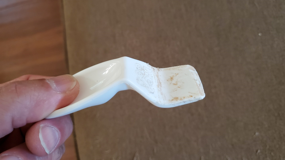
Started the process and so far so good but one thing i just noticed is my box is missing the inner torsion spring, snapped at the attachment. Anyone know exactly what the specs are on that spring? It looks like a 3 ring but hard to tell the correct dimensions or what angle it should be. Going to try to grab one on amazon if i can, thanks.

-
Both the inner and the outer really held up well. I would have no problem recommending them. Some people mentioned they had fitment problems maybe I got lucky but it fit perfectly and normal weather stripping contact black cement was all I needed. Now I did go really slow and only did a section at a time mostly because I just didn't have the ability to remove the hatch and do it properly I had like 20 clamps per side I would do a side move on to the next side and go in four turns so it took me like 4 days and maybe that's why it held so well because of the amount of Vice and the length of time it took me to do it
-
I'm not an electrical expert but I believe acceleration should be increasing voltage in the car and so maybe the horn only works when you accelerate because at idle your voltage is too low. Have you tested voltage either across your battery or across the leads to the horn? I don't know what values they should be but it does sound like increase voltage is enough either through the relay or at the horn to make it work when you accelerate.
-
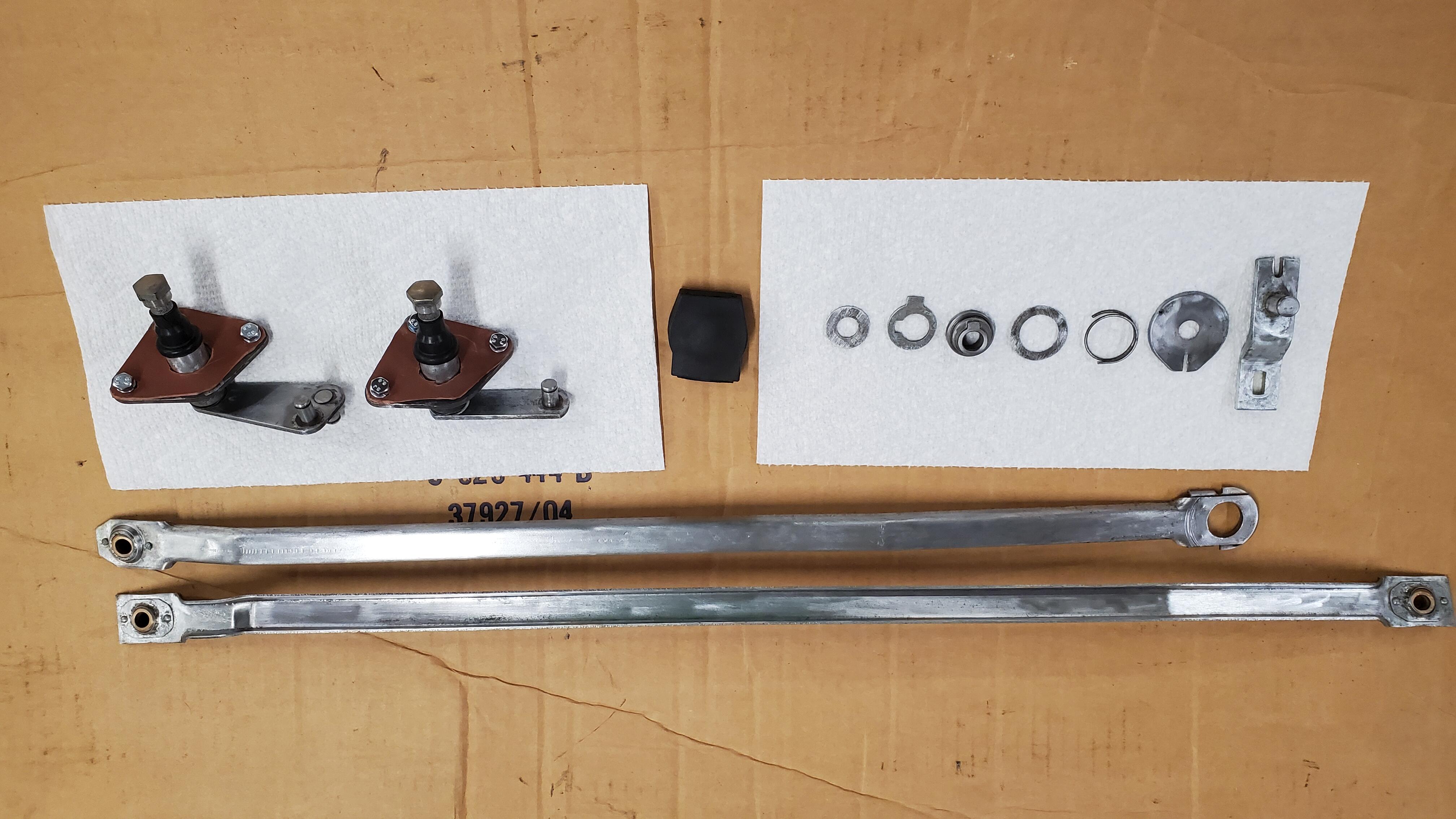
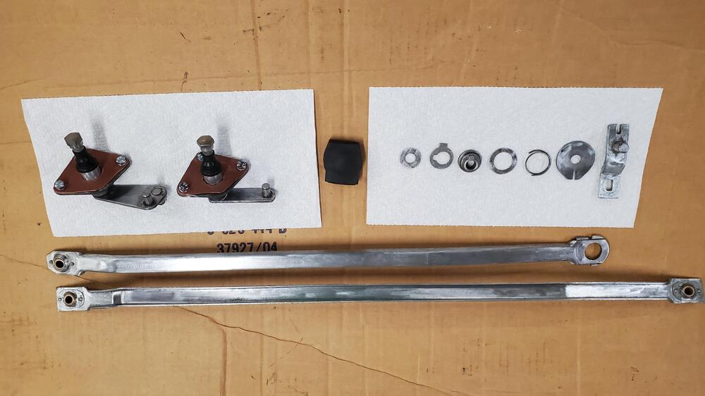
thanks but thats a shot of the section i worked on and restored, you should have seen the before 🙂 Heres the full parts from the linkage and motor arm heres a shot of the closeup arm to the motor I dont recall there being anything more than a nut and lock washer / flat washer to the motor conenction
-
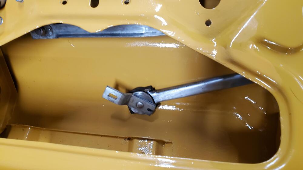
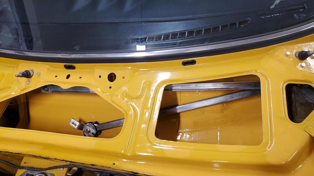
it sounds like maybe you put it back together not exactly as it came apart. Did you take lots of pictures to see the orientation of arms and order of pivot and end assembly? Can you move the arms at all by hand when disconnected from the motor? If its all connected in proper order they should easily wipe by moving the pivot arm that would be connected to the motor. They should move freely, there's nothing to prevent that once disconnected from the motor. Heres a pic of what they should look like and the orientation without the motor
-
Great work what does Dave's harness do? I'm not familiar with that.
-
Yes just follow Steve's instructions disconnect the battery on the negative side take off the clamshell under the steering wheel disconnect the wires and harness running to the switch and you should be just fine I was able to test it while it's still connected pretty simple
-
I'm sure you can but I would first follow the instructions for continuity testing that Steve gave me in that post to make sure it's a good working switch before you attempt to take it apart and clean it. As for the Honda upgrade personally I don't think it's necessary if you take the effort to clean and refurbish the wiper arms pivots and other moving Parts on the motor. From what most people said in my research the lack of speed really isn't the motor it's the 50 years of wear and tear on all the moving parts that slow it down.
-
Great job when I got to this stage those tubes were so clogged and corroded inside it took an overnight bath in WD-40 and then I actually had to boil them in water to soften whatever was inside to finally loosen it enough to blow clear hopefully yours aren't so bad
-
Actually all the ones I've seen have always had two full coils with the bend at the end of the second coil that's why if you notice in my picture my Bend was snapped off and bending to make a new shorted me by about a half a revolution
-
Excellent job a little beyond my means at the moment. One thing I would add is make sure the rotation is in the correct position I see these two Springs are different and one may not work as well since the point here is torsional resistance and not compression the rotation has to be in the correct direction.