Cruzzar
Free Member
-
Joined
-
Last visited
Everything posted by Cruzzar
-
If you look at the 1975 factory service manual under the section for the tach it shows the wiring schematic. If you follow this wiring diagram it does not show any wires (ie. blue wire) going to the TIU which is what was confusing to me as to what would cause the tach to short out the ignition. After reading SteveJ's response I went to the section on the distributor and looked at the area for just the TIU you will see it shows where all of the colored wires go that attach to the TIU, one which went to the blue wire from the tach.
-
Just as a follow up, I removed all of the wires going to the TIU and hooked up the tach and all is working. I know that it is pretty hard for an aftermarket FI manufacturer to include every bit of info in their instruction manual but somewhere at their tech line info center there should be a note that the TIU should be completely disconnected when switching to the turbo distributor.
-
Megasquirt has only two wires going to the coil (plus the blue wire for the tach signal on the negative side). I have double checked that they are correct. Megasquirt triggers the ignition from the turbo distributor module . I have completely removed the ballast resister. It sounds like the stock transistor ignition unit is killing (grounding out) the coil which is controlled by megasquirt. Since I do not have the stock distributor installed, it sounds like the transistorized ignition unit is useless unless the accompaning wires serve some purpose and it sounds like they are not--thanks SteveJ I will try disconnecting all of the wires going to the TIU and isolate them and see if it works.
-
All guages were working before I made the switch to a megasquirt fi system. I found that the tach wire (blue) was shorting the ignition system out when it was attached so to get it turned I just left it off. When the engine is running it will short out the ignition if I attach it and the engine dies. I thought it might be the tach so I pulled the guage and wire plug out of the dash completely and the engine still dies if I try to attach the ble blue wire while it is running so I don't believe that the tach is the fault. Looking at the schematic in the service manual it appears that the blue wire goes to a resistor but I don't know where that may be, anyone know? I have removed the stock distributor and am using a turbo distributor for the crank angle sensor for the megasquirt. Can I remove the transistor ignition module that is located on the passenger side next to the fuse panel or does the tach need this to produce a signal and if so, could the module have a short in it and this is causing a short to kill the ignition? One other thing, with the engine turned off I checked the blue wire to see if it was grounded and it wasn't , this is why I am asking about the module. When I power up the car it may be shorting out but isn't shorting when not powered up. Any suggestions will be appreciated.
-
Midwest price for the correct Nachi bearing was $19.20 plus tax and shipping. EuroDat thanks for the part num.
-
Sorry, Zed Head, I should have passed the info on. Midwest Transmission Center. They have complete rebuild kits as well as individual parts, synchros, bearings, gaskets, seals, and etc. Midwest Transmission Center, Inc. - Your Transmission, Transfer Case and Differential Drivetrain Experts
-
Thanks for the links, I was able to find a supplier that could get me the correct bearing.
-
I have a 1995 240sx transmission in my 280z and am in the process of rebuilding it. I need to replace the front bearing on the counter shaft. It is a 62 x 22 x 17mm bearing. It is a Nachi bearing which is the original bearing for the trans. I would like to replace it with a new Nachi bearing but I just can't go to a Nachi bearing distributor and order it. It is a proprietory bearing made just for Nissan and must be purchased thru them. I called Courtesy Nissan and they want to know the VIN num. on the car which I don't have because I only purchased the trans. Does anyone know the part number for the front bearing on the countershaft for this 5 speed. The number on the bearing is a 22BC06S5X. I have already looked into getting a German bearing (Fafnir, NGK, etc.) but the ID of this bearing (the 22 mm) is not manufactured by anyone except Nachi. I don't know of any quality manufacturer of bearings that I can turn to in order to get my trans back together.
-
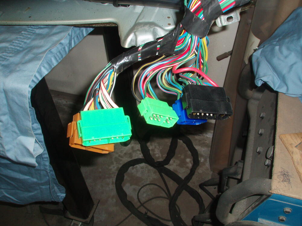
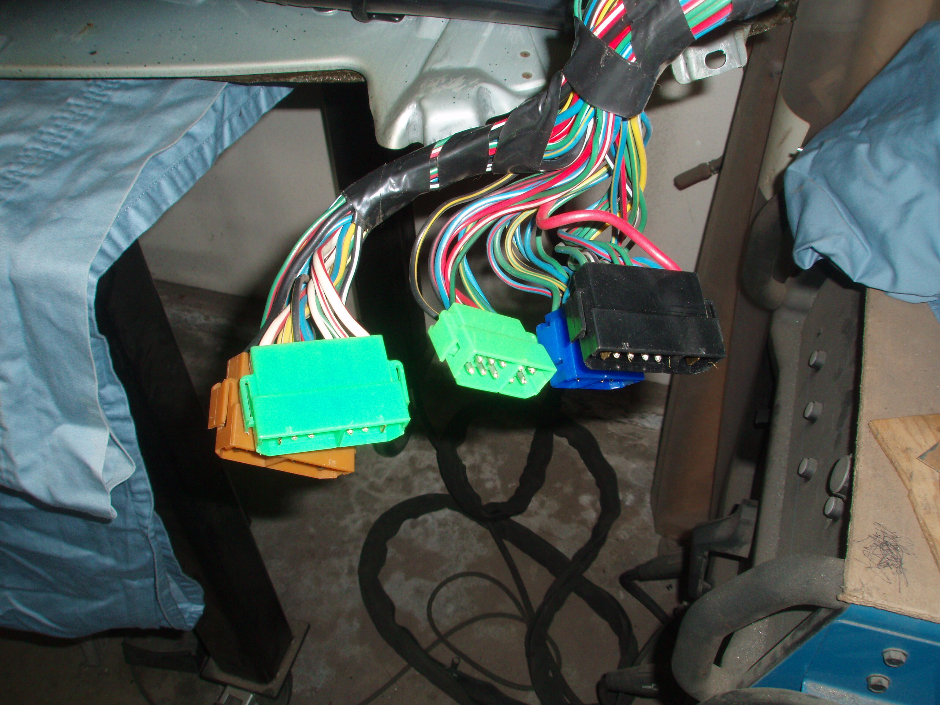
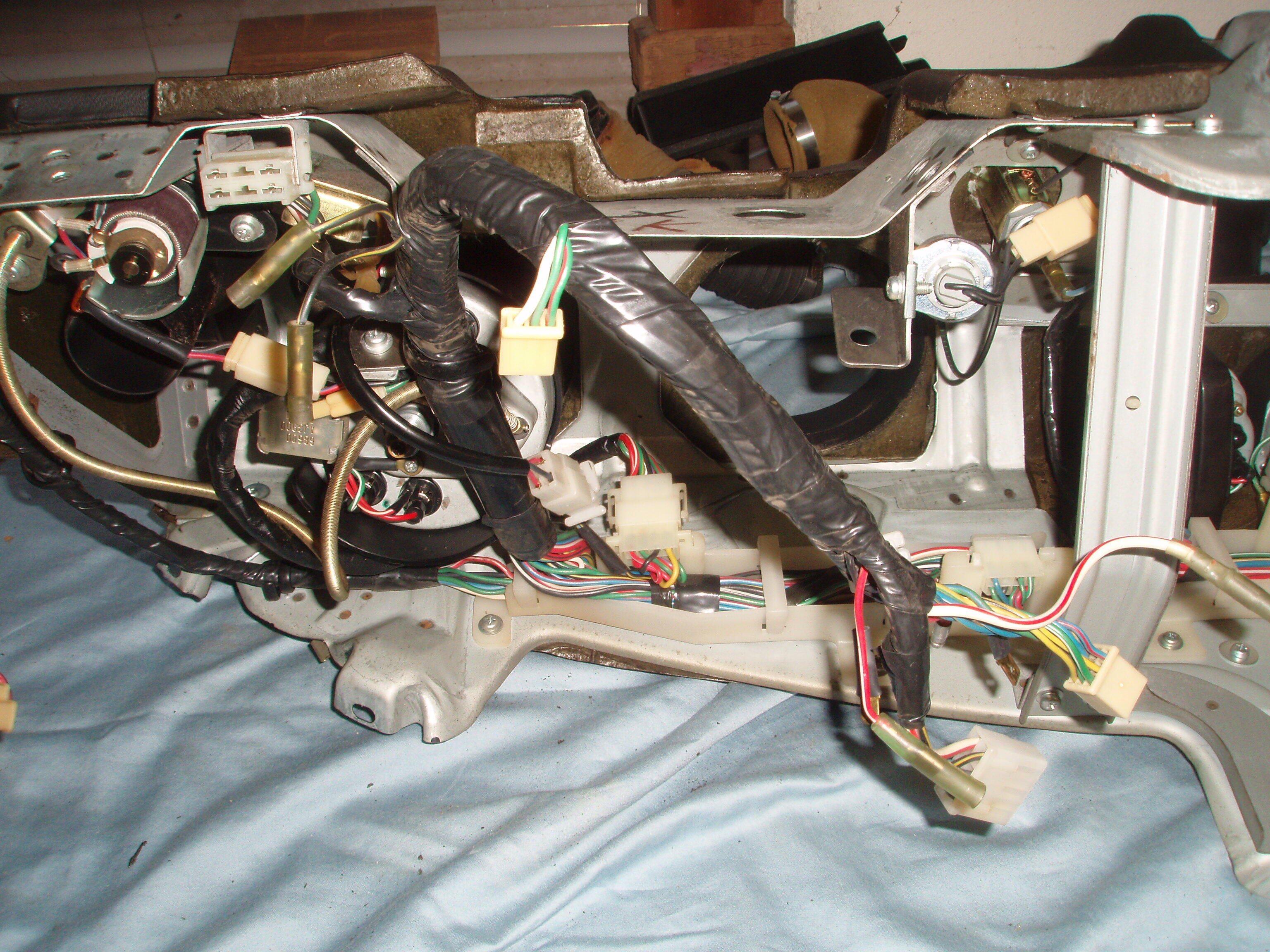
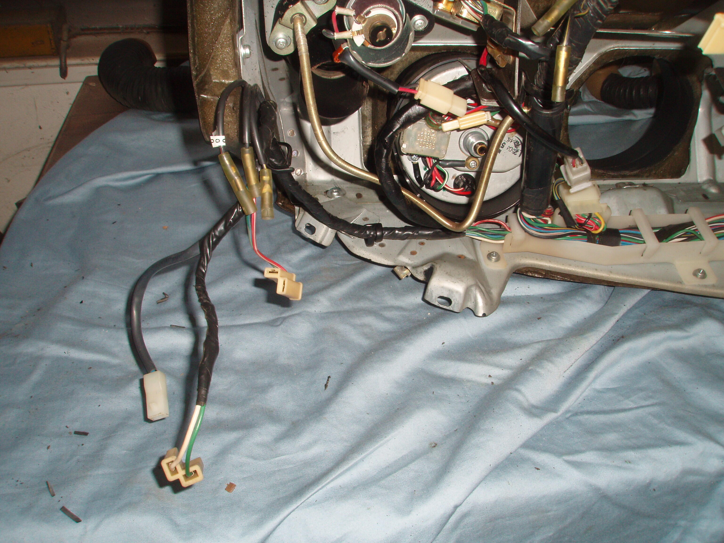
I have pulled my dash out of my '75 280Z to replace the heater control valves and heater core. Before doing so I tried to get a better idea of which wires that needed to be undone before removal. I have the Factory service manual and have watched several YouTube videos but none do a very good job of identifying exactly what the wires look like and where or how that can be gotten to (is it under the dash or after the dash is pulled out a little). I realize that this may be a little basic for all those who have already pulled their dashes and pretty much know what and where to find these wires. The bolts are pretty much no brainers. The speedo cable was located in an area that I could not get my hand up into and then be able to turn the knurled base to unscrew it. I was able to undo the two screws that holds the tac in and simply pulled it out far enough to get my other hand in there and with both hands I was able to unscrew it. The wires on the passenger side were straight forward, just unplug the five connectors just above the passenger's right knee under the dash (first picture). On the driver's side, you must unplug the two bullet connectors for the brake light switch and a white plastic 6 prong connector just under the edge of the dash between the steering column and the headlight switch. These are shown in the second picture. The white 6 prong plug is in the upper left with the two bullet connectors just below. The dash is upside down on my work bench so it might be a little confusing. These must be disconnected by getting under the dash. For the rest of the wires I found that if I pulled the dash out about 4 inches, that I could simply look back there and disconnect them as needed. The third picture shows these disconnected wires. There are 3 bullet connectors, 2 'L' shaped white plugs, and 1 white single wire plug.


-
If any of the carbs were removed from the manifold when you made the transfer onto the 240 then they will need to be resynchronized. There are probably Utube videos on how to synchronize multiple carb applications using a Unisyn guage or something equal. Even with the correct main jet, emulsion tube, idle jet and venturi if the carbs are not synchronized it may run terribly or not at all.
-
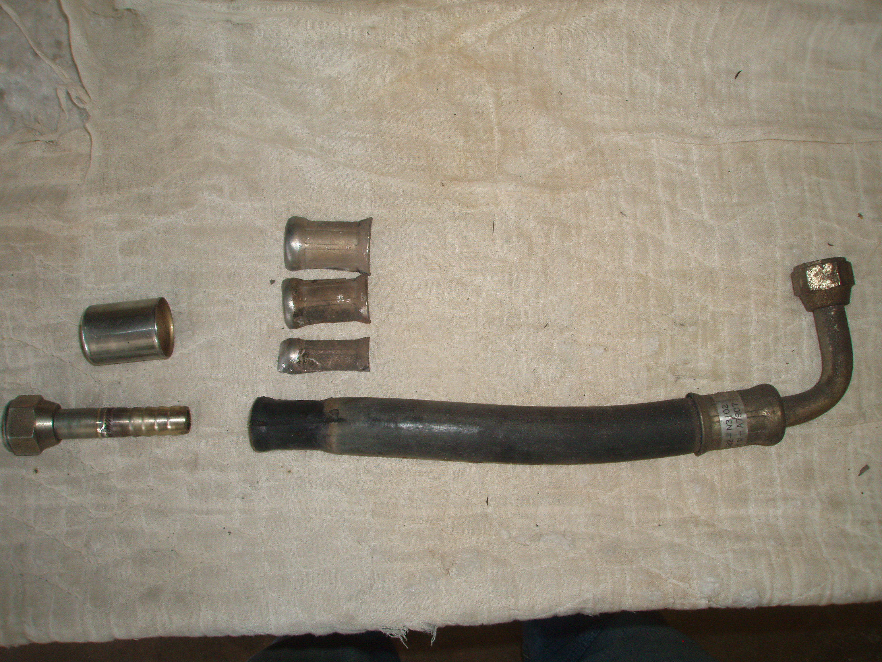
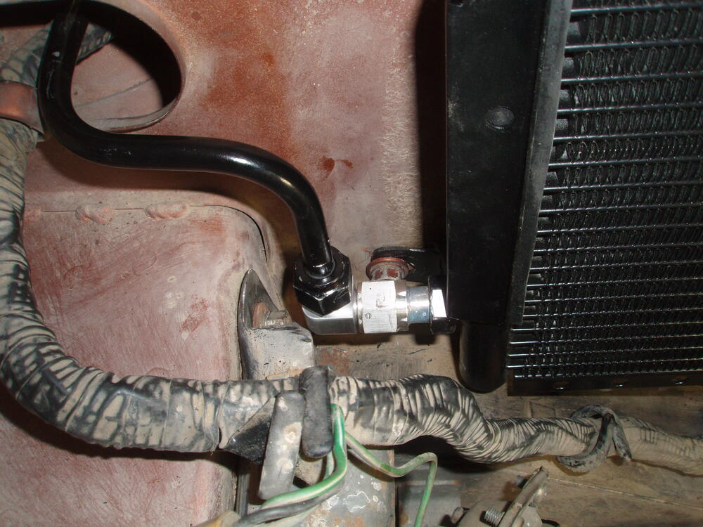
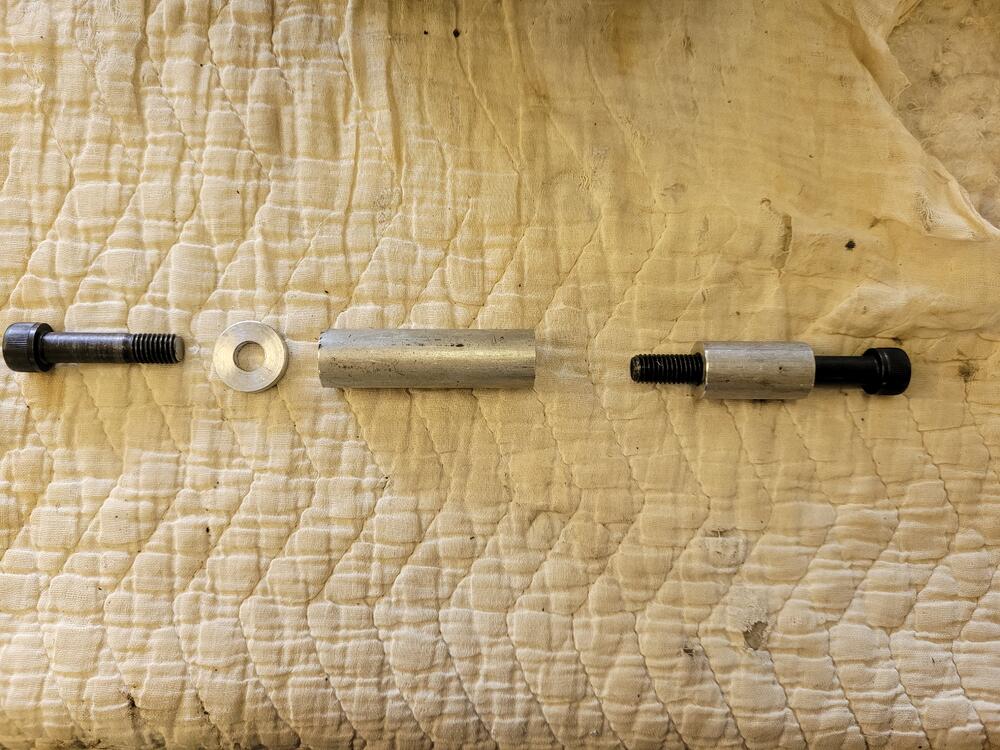
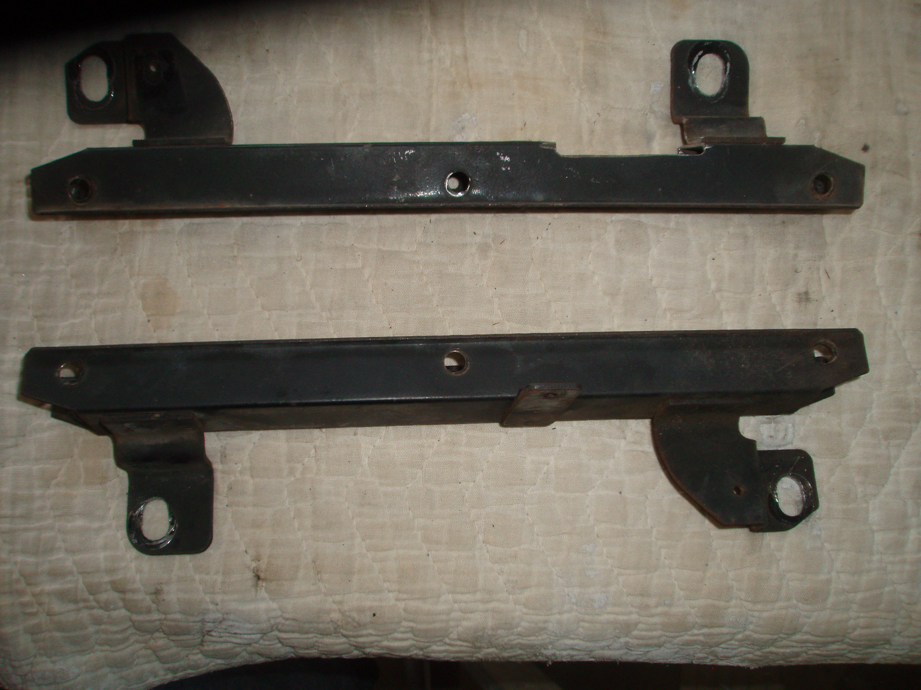
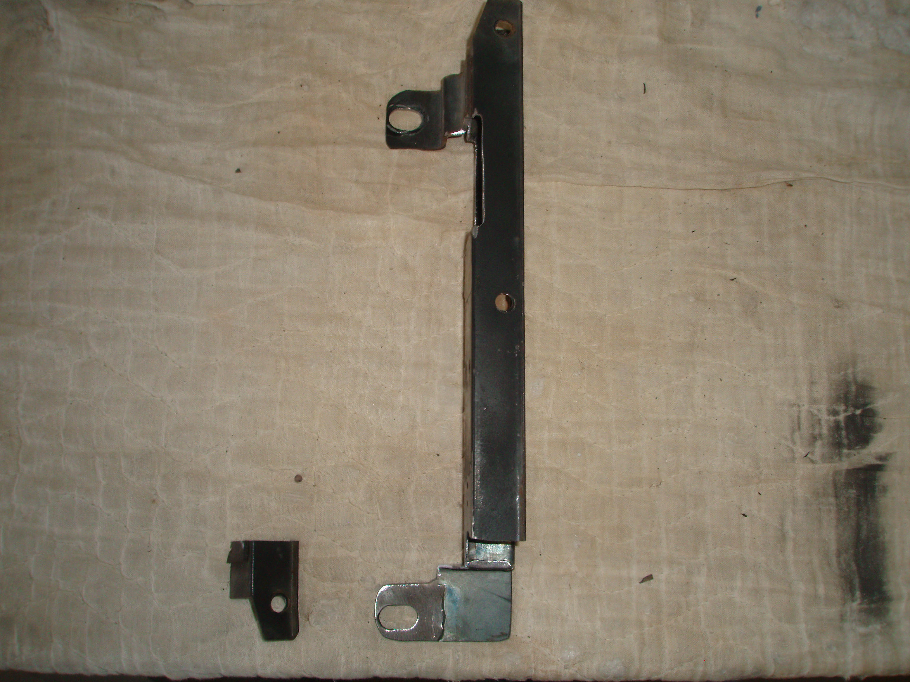
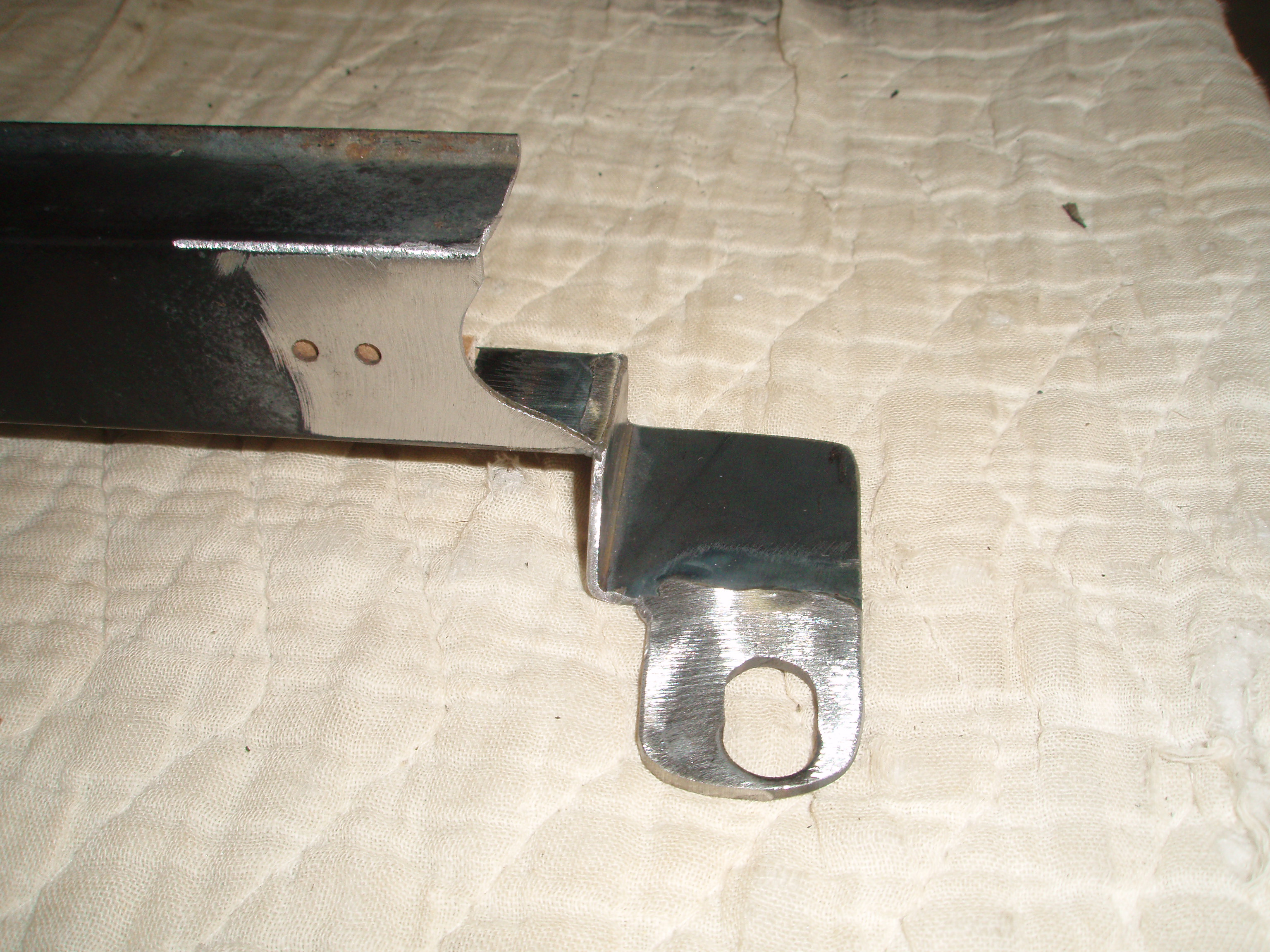
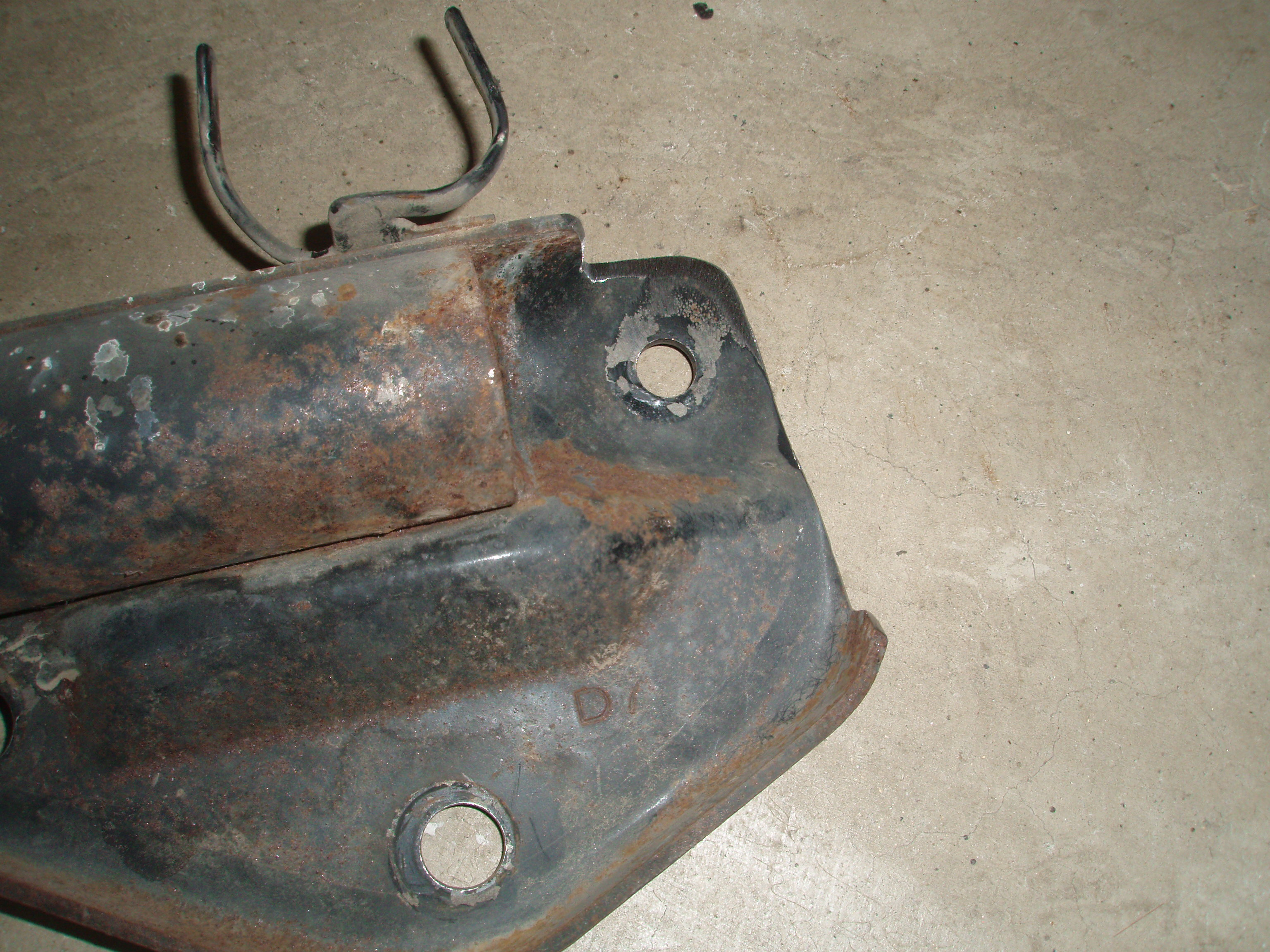
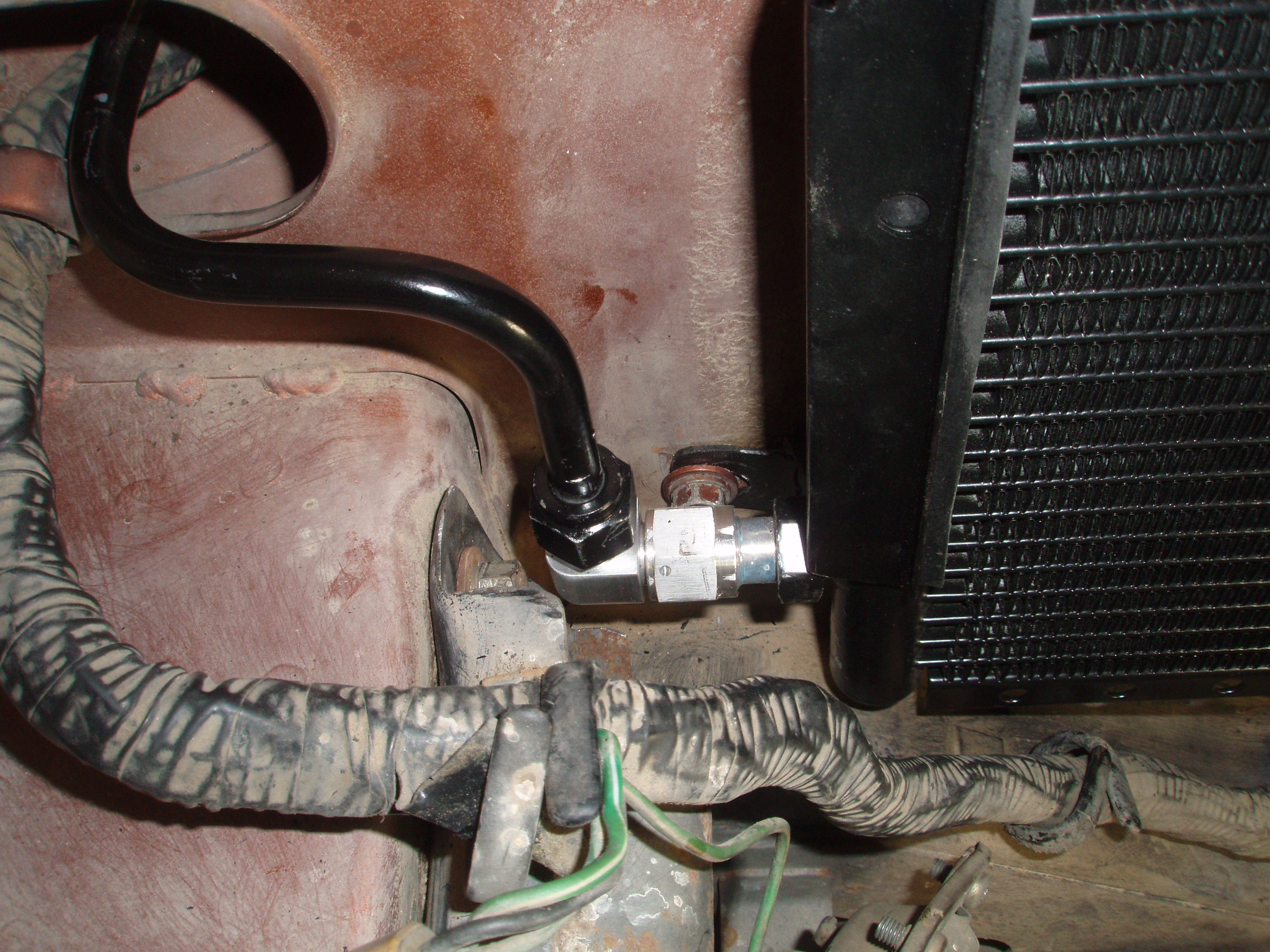
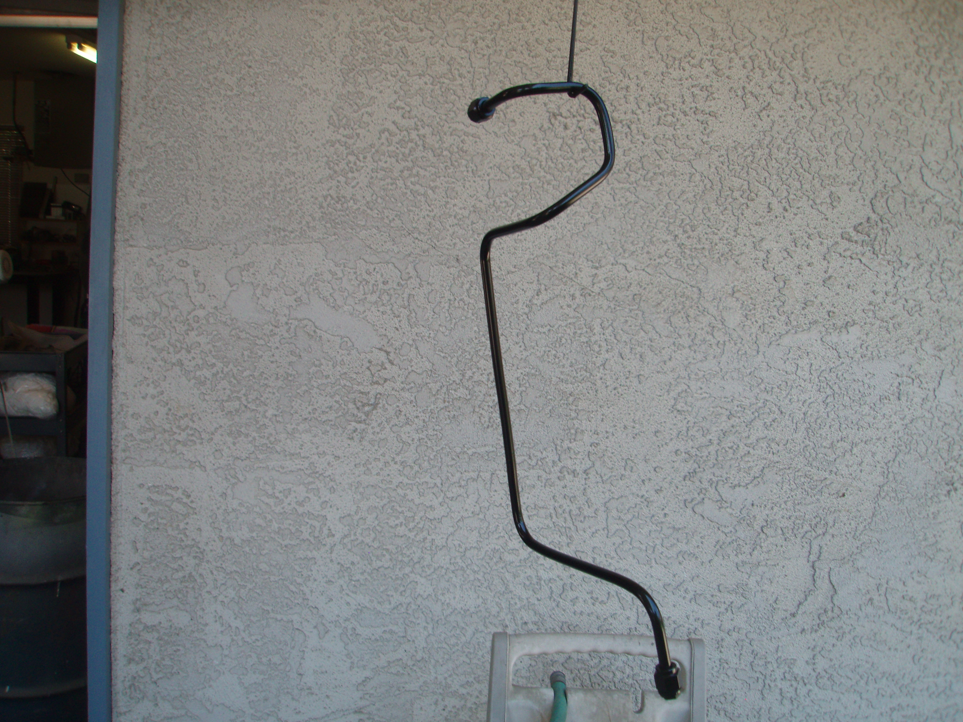
I thought I would post what I have done to complete my retrofit from R12 to 134a. I ordered a Vintage Air 12" x 24" condenser from Summit Racing since the old condenser was a 12 x 24. The new condenser comes with #6 and #8 male o ring fittings. Since I am trying to keep this retrofit stock looking as possible I found that you can remove the stock condenser's brackets and reuse them on the new condenser with a little modification. Since the new condenser is slightly wider you will need to slot the 4 mounting holes about 3/16" toward each other. The only other modification needed is on the left side bracket and you will need to make an opening for the #8 male fitting to go thru and removing a small section of the bottom to make room for the #6 fitting. In the process of doing this last step you will need to remove the bracket that attaches to the core support but you still need this support so you will have to modify the attachment point. I made a small bent piece of metal and welded it onto the bracket that kept the hole location correct before I cut off the bottom porting. Here are three pictures, the first is of the stock brackets after unbolting them from the old condenser, then the modified left side bracket and then a close up of the bottom portion. To attach these brackets to the condenser it is simply a matter of using 3/32" neopreme strips between the brackets and the condenser. If you have ever reset door window glass back into the u shaped window mechanism you know what a grip this process has. Just shoot some Windex window cleaner on the neopreme and brackets and shove them together making sure the four mounting holes align up to the holes in the core support. Upon mounting the condenser you will note that the condenser's #6 and #8 fittings are very close to the top air inlet for the cabin and the front bumper bracket. You will need a tight 90 degree #6 fitting (Summit Racing) and a slight trimming of the front bumper bracket's rear most flange. Pictures 4 and 5. To replicate the hard lines I purchased two 4 ft. premade aluminum (U-Bend-Em) hard lines. The #8 line with male and female o ring ends, the # 6 line with female o rings on both ends. You can order these lines in various lengths but I chose to try to make it look stock hence the 4 ft. length. If you choose the 4 ft. length for the #6 line you will have to be careful when bending that you allow yourself the ability to physically install the bent line in the hole in the core support and around all of the other stuff that is in that area. I used a new drier that came with #8 flare fittings so the original hard line from the firewall to the drier just bolted up like stock. On the other side of the drier going to the condenser I ordered a #6 flare to male o ring adapter which then bolted up to the #6 female end on the hardline from the condenser. On the #8 fitting on the condenser I had to trim slightly the metal that surround the cabin air inlet tube in order to get it installed. I then I bent the tube 180 degrees (use tubing benders on all the the hard lines) so it traversed across the condenser and then thru the core support hole like original where it attaches to a #8 female 45 degree hose fitting. I will use the stock bracket to attach a line clamp onto the tube to reduce vibration as like it did stock. At the end of this hose I needed to attach to the compressor. I could not find a #8 90 degree fitting with the filler port on the side so I took a 135 degree fitting that I already had that had the filler port on the side and very carefully straightened it back to 90 degrees and installed it. For the #10 line going to the firewall I used a #10 135 degree fitting with filler port but on the other end I ran into a problem. The #10 hardline that is stock in the Datsun is a weird size. It is a #10 hardline but it has a #8 male flare fitting end. So finding a fitting that goes from a #10 hose to a #8 female flare fitting could be a problem until I realized that I already had one on the old hose that I removed. I simply very carefully cut off the metal crush sleeve, got a new sleeve and squeezed it on like any other fitting. This system results in both filler ports to be easily accessible and next to each other on top of the compressor. In the following pictures I show the bent to fit #6 line already painted and ready to be installed. The next, the # 8 hard line test fitted (I will paint it before final install), the engine side install, and then a pic the # 10 line with #8 female line removed from the original hose. If I were to do this again I would see it I could find a condenser that had the #6 and #8 fitting closer to the center of the condenser as that would allow more room to get the hardline on without any interference from the car's body. I might also order a longer #8 hardline and bend it to go around the outside of the condenser as opposed to going across it. One last thing I did was to upgrade the blower motor to the 1998 Kia Sportage blower motor. In addition to making the hole about 1/8" larger in diameter you will need to change out the three spacers to new ones to form a good seal. The spacers that I made were out of some 1/2" round stock with a 5/16" hole and .666 long.


.thumb.jpg.afada0a4ce6008ed0c3a35eda4263d6f.jpg)
.thumb.jpg.786451715a9948e161655bcb7dfacd56.jpg)

-
It sounds like you need is a crimping tool that is small enough to put enough pressure on the top antenna section to hold it to the filament. I have made a simple crimping tool using a vise grip pliers and a Dremmel tool with a small cut off wheel. You need to grind a small groove into each side of the vise grip's jaws that is slightly smaller that the antenna's porting that is to be crimped. It would be helpful if you had several test pieces so the amount of crimp could be adjusted but that may not be possible.
-
Just checked the old oil and it looks like clean engine oil. No evidence of oil breakdown or contaminates so I will drain the new compressor and reload with 6 oz. of Ester oil. I am still waiting for some fittings and will post when all is back in working order. Thanks for the tip on the Ester oil, I really didn't want to break the oil ring seal on the expansion valve.
-
Dave, I am replacing: the compressor, the condenser with a PF unit from Vintage Air, the drier and the low pressure hose. I have heard of using Ester oil because of its compatibility with the mineral oil but have never run into a situation where I would use it. I am going out today and draining the old compressor's oil and will take a good look at it to see if there is any indication of contamination, if it looks good then I guess I drain the new compressor's oil and replace it with Ester oil and I should be good for vacuum and recharge. Sound OK or have I missed anything or any other area that should be addressed.
-
My understanding is that the original compressor oil is not compatible with the new pag oil for the 134a. If the mix they have a tendency to coagulate. Do you think if I try to flush with the expansion valve in place that I will get enough volume of cleaner to flush out any remaining oil in the evaporator. The system has always had pressure in it, I am making the change because the original Hatachi compressor was starting to make noise. I don't know what the origin of the noise was but I did not want to chance it plugging up the expansion valve because of its unobtanium supply. I am open to all comments?
-
I need to flush my evaporator and I am wondering if anyone has any experience doing this? The problem that I see is how to backflush. I have never flushed an AC system so any help will be appreciated. I am assuming that I have to take the expansion valve out of the system. can pull the existing expansion valve and flush the #10 line going to the firewall but how do I flush the other direction? How do I insure the flushing liquid goes thru the evaporator coils before it exits back toward where the drier hooks up? Do I need the make a fake expansion valve the will have a barbed end to attach the flushing solution to and the other end machined to bolt into the expansion valve cavity so it directs the flushing solution to the approximately 5 or six evaporator lines? Please ignore the two picture below if the show up. I somehow got them on this post and I can't figure out how to edit them out.

-
I forgot to mention, the correct length belt for this new modification is a Gates XL 9350 (15/32" x 35 3/8" or 12mm x 899mm). I barely fits over the pulleys with the tensioner pulley completely slack and when the tensioner pulley tightens the belt properly it still has about 3/4" of travel up.
-
Switch the two wires on the fuel pump, if they are backwards the pump runs but runs backwards and it will never start. Ask my how I know.
-
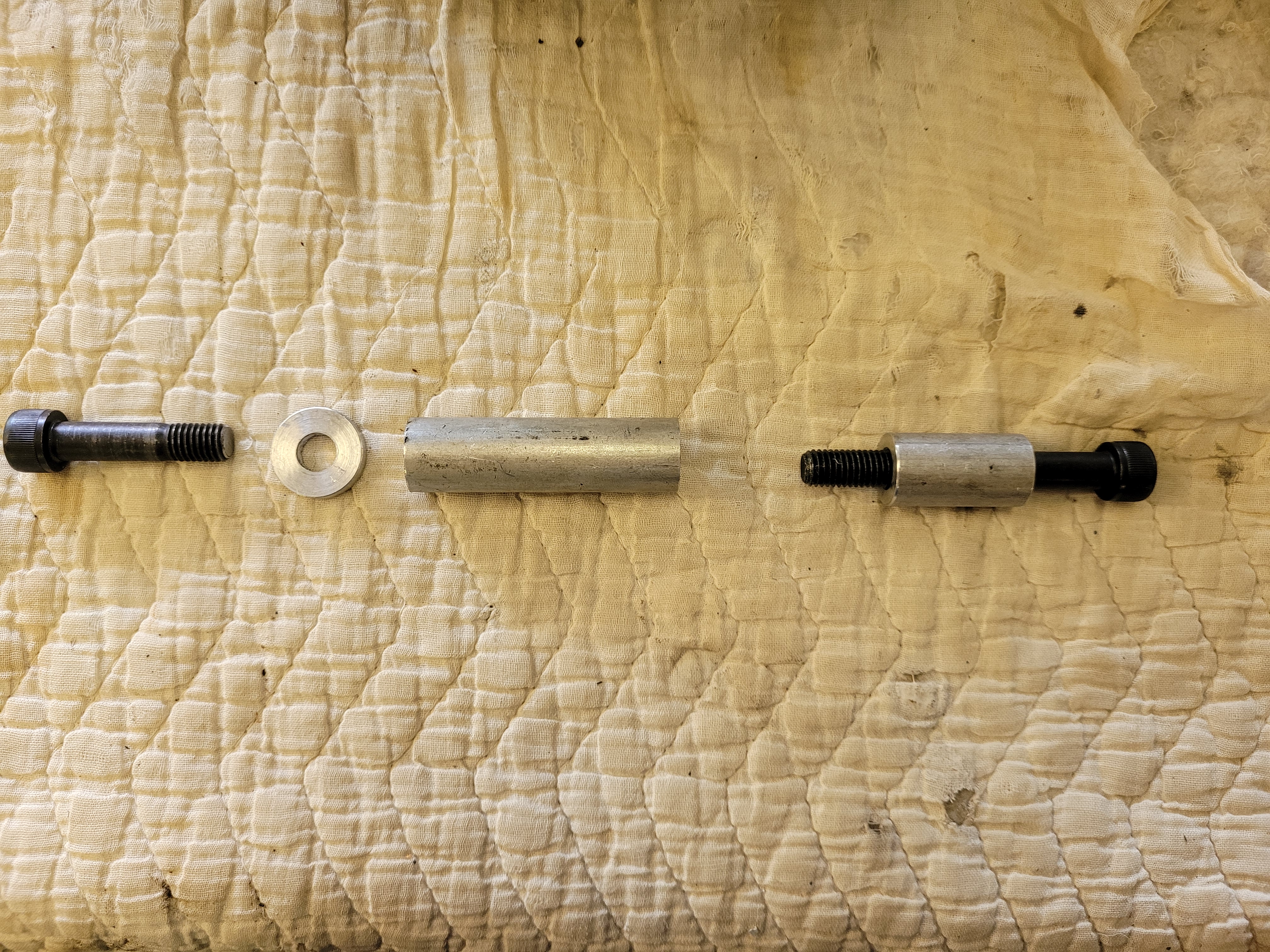
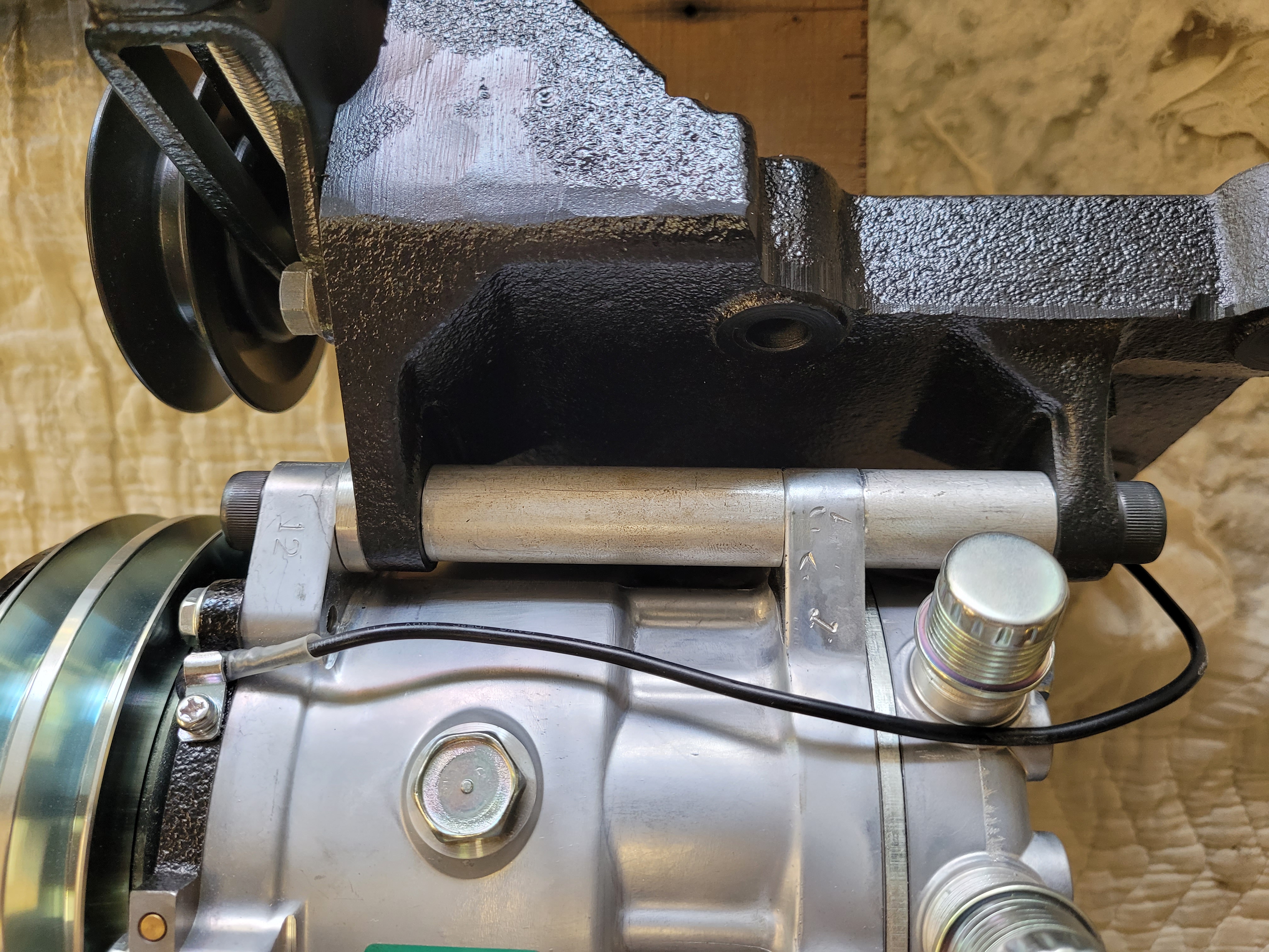
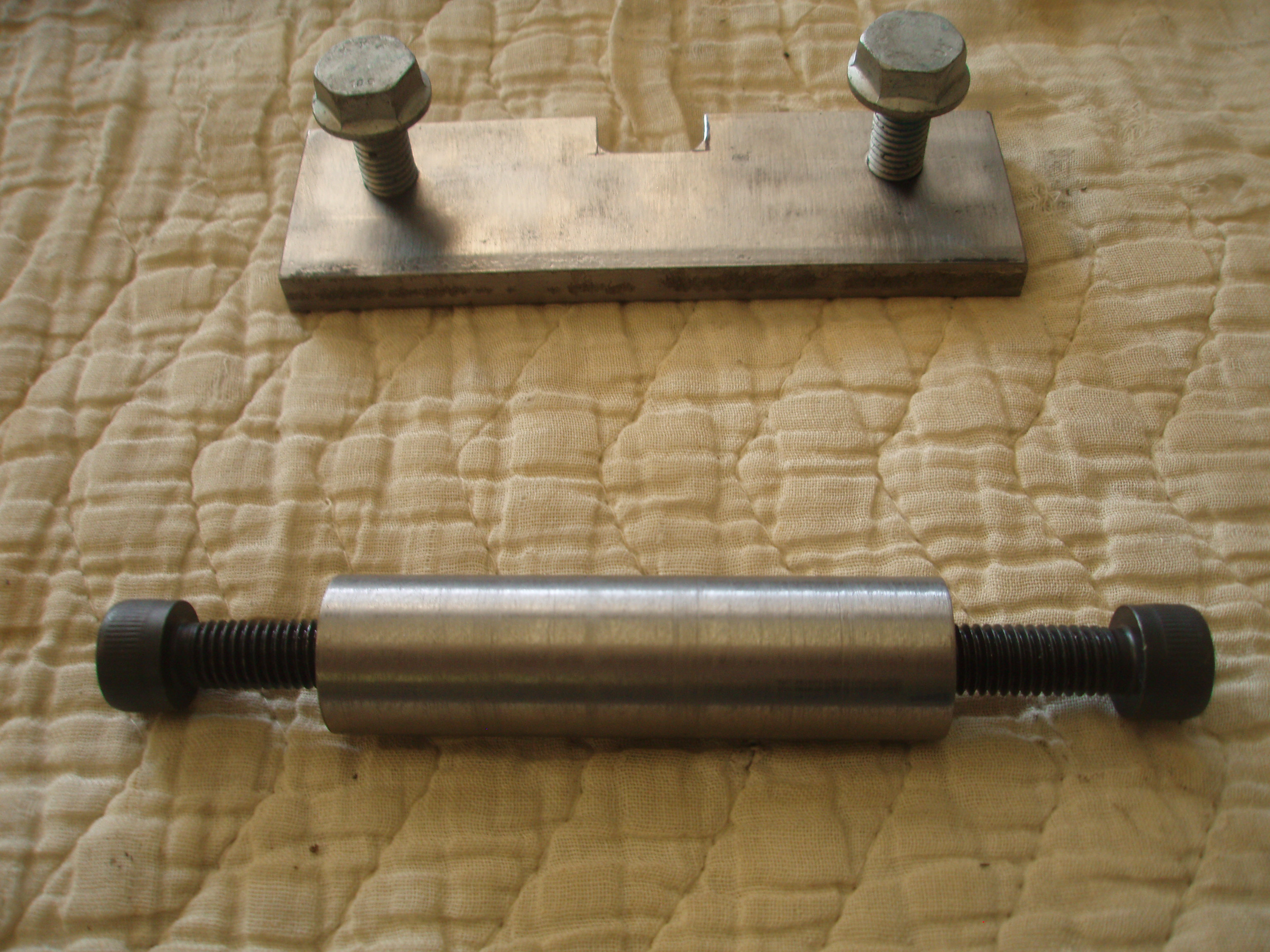
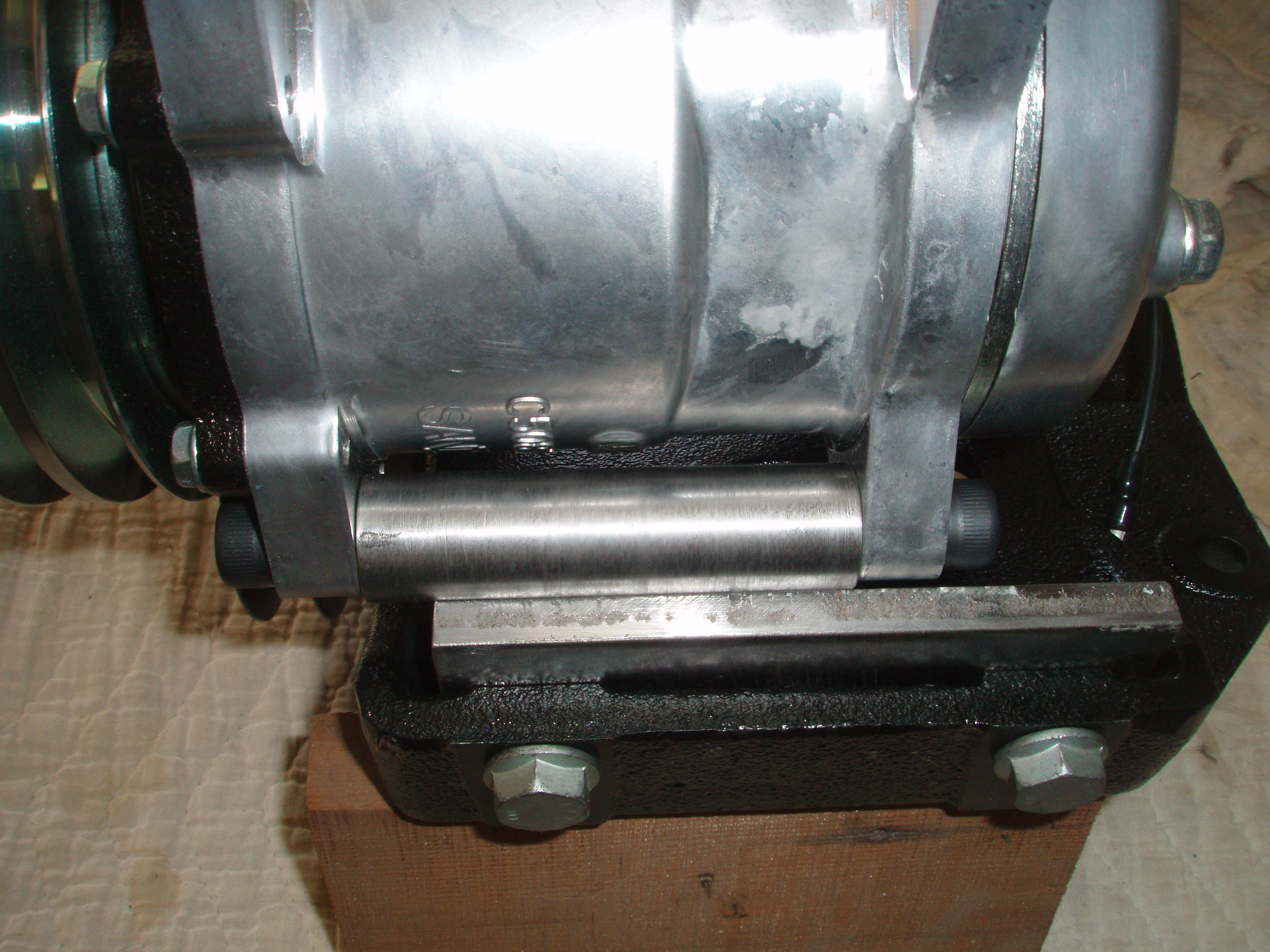
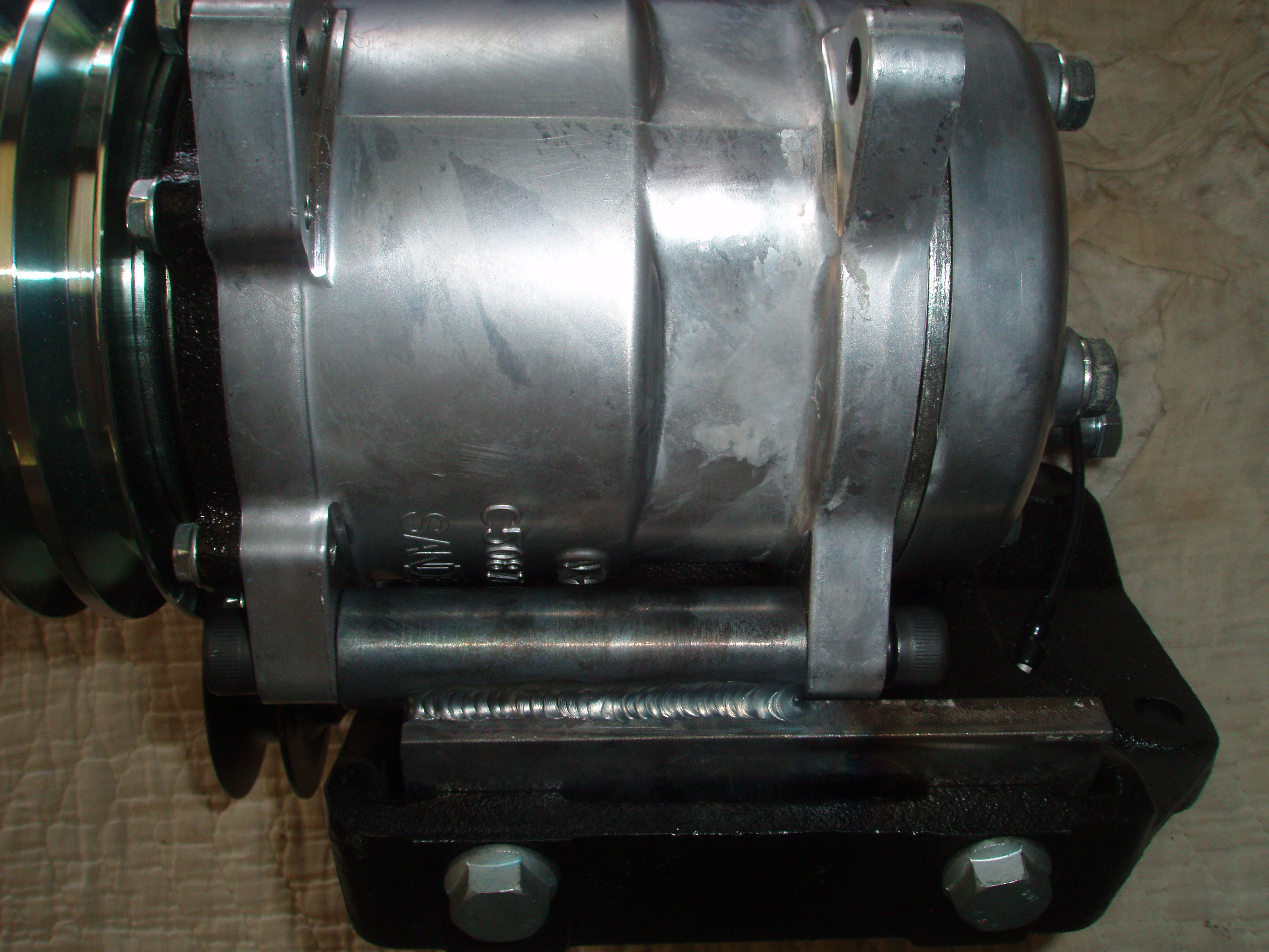
I thought I would share how I went about converting my old R12 system in my 1975 280Z to R134a. My system charged up OK after sitting dormant since 1995. It still had a charge in it but not enough to cool the air. Once charged it put out about 50 degree air on a 102 degree day (good) but the old Hatachi compressor made some really nasty noises (bad). The compressor was louder than the motor while driving down the road. I worried that the dying compressor would contaminate the system and if it plugged up the expansion valve I would be up the proverbial creek without an adequate means of propulsion. I am trying to keep the engine compartment/car looking relative stock. I upgraded to a Sanden 508 compressor and then adapted it to the stock compressor bracket that mounts on the side of the L28 block. I chose to stay with the original bracket because it incorporates the belt tensioning pulley and it is stock. I know that you can purchase aftermarket brackets that will bolt up to the block (and I have to believe that they have to weigh a lot less) but to tension the v-belt you must rotate the compressor and again it does not look stock. I could have made my own bracket but it would have been similar to the stock bracket. Unfortunately the mounting ears/pads for the Hatachi compressor do not match up with the Sanden but by making some spacers and a bottom bracket the Sanden bolt up to the Datsun's bracket with no modifications to the bracket. To do this adaption you must have access to a welder, a metal lathe, some 7/8" round stock, a small piece of 3/8" flat stock and a good caliper to make some accurate spacers. First I made a small spacer out of 7/8" dia. material with a 10mm hole (you can use a 'X' letter drill) that would align the second groove of the Sanden's pulleys with the stock tensioner pulley on the Datsun's bracket. Once this is done then you can make two additional spacers. Each of these spacers must be made so that they just barely fit in position. If you have too much space you risk breaking or cracking one of the mounting ears off your new compressor which would probably ruin your day. In the first picture you can see the arrangement of bolts and spacers. You will need to purchase metric allen head bolts because of the space needed to tighten them up will not accommodate a hex head bolt. From the left I have a 42mm long bolt, a .184 thick spacer, the next spacer is drilled and tapped for a 10mm x 1.5 on both ends to allow the tightening of the two opposing bolts. The next spacer is drilled all the way thru and a 80mm long bolts passes thru it and threads into the previous spacer. Hopefully the second picture will show how all of this goes together. In order to attach the bottom compressor mounts you will need a 1 1/2" x 5" x 3/8" piece of metal that is notched to allow it to fit in the area that the old Hatachi compressor bolted to. Cut your metal, notch it and transfer punch two marks that will be drilled and tapped for 10mm x 1.5 threads. You will also need to make a 7/8" diameter spacer that fits between the two bottom ears of the Sanden compressor (get a good fit with very little clearance). This spacer needs to have both ends drilled and tapped for 10mm x 1.5 threads to accommodate two 10mm alllen bolts that are 30mm in length. You will need to make the flat plate out of 3/8 and the bottom spacer out of 7/8 diameter stock so that when the two come together there will be enough area at their intersection to complete a good weld. Bolt the compressor up to the bracket's top mounts with your three spaces and bolts, attach the flat plate to the bottom of the bracket with 10mm x 28mm long bolts, mount the bottom spacer onto the Sanden's bottom ears and rotate the compressor so that the bottom spacer and flat plate meet. Make sure your pulleys are aligned, my narrow spacer (.184)may be a little different than your application, tighten up the top bolts and spacers and tack weld the bottom spacer to the flat plate. I then pulled off the bottom bracket and tacked welded it on the back side and reinstalled it to make sure it did not pull out of alignment. It was good so I finished welded it, put it back on and checked it again and then pulled it off, bead blasted it and put a coat of paint on it. Pictures 3, 4 and 5 should help explain. Done. Tomorrow, I will start the install of a new condenser with o rings onto my radiator and how I will go about making connections onto the existing flared hard lines.


-
S30, the condenser that I am using (new from Vintage Air, 12" x 24") has #6 and #8 0 ring fittings. I will try to run a hard line from the #6 condenser fitting to the drier. The drier I have has #6 male flare fittings so the exit side of the drier will mount up to the stock hard lines going to the evaporator. I am going to use one of NostalgicAC's flare to o ring adapters. I will probably have to replace the stock Datsun #6 hard line that goes from the condenser to the drier with a hard line that has o ring fittings on both ends.
-
I am aware of using a flex line between the compressor and condenser. My question relates to the hard line from the condenser to the drier.
-
Before ordering you might check with the supplier about the availability of the carpet. I ordered a rear carpet (loop style) from MSA in February and it is still on back order. I have called them on three occasions and they tell me the supplier has not been able to secure the products necessary to make delivery.
-
As mentioned above I would like to keep the engine bay stock looking . I would like to keep the hard lines going to the compressor which would entail using a drier with compression fittings. I will be upgrading to a new condenser that will have o ring fittings. Hooking up the condenser to the drier would require going from an o ring (on the condenser) to a compression fitting on the drier which would be easy if I were to put a hose in the process of connecting the two. If I try to run a hard line between these two then the only way I see that this can be done is to use an o ring to compression adapter. Has anyone ever used one of these adapters? I have never had the need to make a connection like this on the cars that I have worked on and therefor have never used an adapter like this. Adapters are available from Nostalgic AC. Nostalgic AC - Flare Adapters - Fittings & Hose Kits
-
S30Driver, thanks for the links to drier and pressure switch. I have seen this drier on a Utube video. Question: on the second link (for the pressure switch) shouldn't the pressure switch be a high pressure switch not a low pressure switch as what was originally installed ?
-
I need to replace my Hatachi compressor and in the process I will convert to 134a. I need to find a replacement for my drier. Does anyone have a recommendation for a replacement that has ports that are close to matching up with the existing hardlines. I read somewhere that the later Nissan AC systems used a drier that was a close fit. Does anyone have an application or part number to suggest. I know I can just get a generic drier and make it fit but I would like to keep the installation looking as stock as possible. I have a '75 280Z.


.jpg.4d58e289b064783c23e29bccd0c8d0ce.jpg)
.jpg.6b8381aa49777487b08e61b7389aae2d.jpg)