eastcoastz
Free Member
-
Joined
-
Last visited
Everything posted by eastcoastz
-
I kind of doubt it's screwed in too tightly... I didn't torque it... only did it tight enough so that I wouldn't have anything leak out of it. @Zed Head@zKars - is it possible the square headed plug that I’m seeing (next to where the reverse sensor is installed) was put in place of one of those switches? Or is that the proper location of the fill/drain plug?
-
Thank you. I’ll see if I can pull out the reverse switch and take a picture in the hole. I purchase the transmission as a rebuilt/remanufactured transmission so hopefully it was done right. The only other issue I have is that once in a while it can be a little tough to get it into gear when the engine is cold but I just attributed that to being that the engine/transmission isn’t warmed up yet. It always gets better/normal once the engine/transmission is warmed up. The diagram that SteveJ showed me looks like there is a “top gear” switch right next to the “reverse” switch but I don’t remember seeing another switch that close to the reverse switch. is it possible the square head plug that I’m seeing was put in place of one of those switches? Or is that the proper location of the fill/drain plug?
-
@Zed Head thanks so much for these pictures. It’s great to understand what is pushing the sensor internally. I have tested the switch out of the transmission and it works perfectly fine. I push it in with my thumb and the light goes on and I let go and the light goes off. When I put the switch back in the transmission, the light stays on constantly. I can take a picture but my understanding is that I have the 280zx 5 speed. The reverse sensor is in the passenger side of the transmission right next to the drain/fill plug (which has a square end on it). when you say that the rod may be moving inside the fork… what does this mean? Would I have any other symptoms if this is occurring?
-
Thanks for the reply. I’m 99% sure I have it in the right spot because it worked originally when I installed it but after about a dozen or so times of going into reverse and back to 1st gear, the light came on endlessly so I just decided to unplug it. I would love to get it working again so I wanted to find out what specifically inside the transmission is pushing up against that button on the sensor…. and is it possible for it to get stuck?
-
I have a 5 speed out of a 280zx in my 240z. At first the reverse lights worked correctly but now when the sensor (in the transmission) is connected, the reverse lights constantly stay on. I have tried multiple brand new sensors to no avail. When I put my pinky finger in the hole (where the sensor goes) it feels like something is there pushing in the button on the sensor and I guess not moving away regardless if I’m in reverse or now. My question is this… What inside the transmission pushes up against the this reverse light sensor? Is it possible for it to get stuck? I was hesitant to stick a tool in there to try to push (whatever is touching the sensor) back to its resting position. Thanks in advance!
-
I switched back to points and it's running much better. When I removed the pertronix, I noticed that the plastic piece/ring at the bottom of the magnet piece was cracked... not sure if that had anything to do with the issue.
-
Hello... I've been dealing/troubleshooting a stumble issue at 3500-4000 RPM and above and hoping to get some suggestions for where to go next. Here's a little history on my setup: Original L24 engine bored .30 over Triple Weber DCOE 40 Carbs (currently running 55 idle jets, 135 main jets, and F11 emulsion tubes) Electric fuel pump with regulator set to 5 psi Pertronix Electronic Ignition with Flamethrower Coil (bypassing the ballast resistor) NGK Iridium Plugs (gapped to .40) Vacuum Advance NOT Connected Timing is retarded at the (stock) distributor The issue mainly seems to occur when it's hot outside and the car is warmed up. It idles totally fine, but when I push it, I get a stumble/hesitation at around 3500-4000 RPM and above. On a hot day, I don't notice the issue at all until the car gets hot... and on a cold day, I don't seem to notice the issue much at all. It's really baffling me... I've tried different main jet sizes but it doesn't seem to help. I also installed a heat shield for the carbs and I put in hood vents (to help dissipate the heat), but no dice. I read somewhere that a rich condition could cause the stumble/hesitation when the engine is warmed up, but I experience the issue with all of the main jet sizes I've tried, all the way down to a 125 main jet, so I don't know if that is really the issue or not. Any ideas/suggestions? Thanks in advance!
-
I have noticed that when I toggle between the high/low beam, about 50% of the time when I switch back to the low beams, the headlights completely turn off until I lightly touch/press the T/S switch in towards the steering wheel again. Not a full "click" again... just lightly touching the T/S stalk will cause the headlights to come back on. Any suggestions for how to get this to toggle properly without having the headlights shut off? @dhp123166 - just thought I would get your thoughts here too since you rebuilt/refurbished the switch... any ideas? Thanks in advance!
-
Thank you @SteveJ yeah you were definitely right with the analogy. I appreciate it. I have already cleaned the fuse box pretty well with a vinegar dunk, contact cleaner and brushes. My guess is maybe the contacts are dirty in the hazard switch which is causing the voltage to not be strong when it goes from the hazard switch to the flasher unit. Yes I know I should do it the right way and rebuild the hazard switch but is there harm in leaving a new 12v connection (with an in-line fuse) going to the flasher unit for now?
-
@dhp123166 I got the turn signals working. Thank you very much for all of your help! It turns out that even though I had 12v at the green wire coming into the flasher maybe it wasn’t a “strong” 12v. I connected a new 12v lead to the flasher (as a test) and the turn signals work now.
-
I got the turn signals working. Thank you everyone for your help! It turns out that even though I had 12v at the green wire coming into the flasher maybe it wasn’t a “strong” 12v. I connected a new 12v lead to the flasher (as a test) and the turn signals work now.
-
@Patcon they are incandescent - tried two different aftermarket ones (a single filament model and a dual filament). I don’t think the dual filament one is a 1157 bulb like original/OEM though.
-
Thank you @cgsheen1 No I have not tried jumping the green and white together. I’ll give that a shot. I was thinking I could also try running a 12v “jumper” straight from the battery to the flasher. Wouldn’t this essentially bypass the hazard switch and tell me if there’s an issue with the turn signal switch? Since connecting 12v directly to the harness side of the 5 pin connector causes all appropriate lights to light up (solid) that should tell me that the harness connector and wiring to the lights is good. On the ZCarDepot web site they sell a flasher unit which says in the description that it’s different from the hazard flasher unit. Do you happen to know if I should be using different flasher units for both? I have been using the EF32/EL12 flasher unit. One other thing that I noticed today that was odd… with the front turn signals removed, I could hear the flasher unit “click” when the turn signal switch was up or down but neither the rear lights nor the dash lights (for the turn signals) were coming on. Once I connected the front turn signals, I could no longer hear the “click”. The front turn signals that I’m hooking up are aftermarket turn signals that I just bought at NAPA. This makes me wonder… is the electrical system looking for a specific bulb/resistance for the front signals? Is it not working because I’m not using the original factory turn signals/bulbs? Thank you!
-
Thanks again for all of your assistance and suggestions! I've done so many things, that it's hard to remember what I've tested so far. If I recall correctly, I believe I connected the test light directly to the green wire coming into the flasher/relay and it is bright. Is that what you're asking when you say "have you tried the test light at the connector for the flasher"? If I recall correctly too, the test light is bright (and it blinked) when connecting it directly to the 5-pin connector on the switch itself (and moving the lever up/down). Shouldn't that mean that everything is working correctly up to (and including) the switch? When I did this test, it was again just one test light on one pin at a time, so I need to test two lights at the same time. If you connect a single test light to your white wire, does the bulb light up brightly and blink? Just curious if you have tried this before to know what someone else's result is?
-
Thank you @SteveJ! I have definitely studied that diagram for many hours it seems (haha) and have been racking my brain on this issue. I'll have to test it again, but I'm 99% turn that connecting a test light to the white wire (and ground) caused the light to just light up very faintly. Is this what is supposed to happen? If not, do you know what may cause the light not to light up brighter and/or flash on the white wire? In the other thread you had said this when I mentioned that it lights up very dimly on the white wire: When I get a minute to do some more testing, I plan on pulling the wires out of the harness side of the connector and plug them directly into the pins on the switch connector. That way, when I move the lever up/down, I can more easily test the harness side of the wires to see if they are getting 12v flowing from the switch to the harness.... this should be a good test, right? Yea, my brake lights work perfectly. I have not tested the voltage at the turn signal sockets... I will do that too. I was also thinking... I have just been holding a single test light to the pins... I wonder if I need to try to hold two test lights at the same time (to the appropriate two pins) to see if there is an issue with the circuitry lighting up two lights at once. Maybe one light is working, but two lights is putting too much load on it? But if that were the case, I would think the rear turn signals should light up when I have the fronts removed and they don't 😞
-
Hi! I thought I would start a new thread since the old one is now buried with a lot of different info. I have a 1971 240z and the turn signals are not working. Here is what has been done/tested so far: Turn signal switch refurbished/rebuilt Hazard lights work perfectly Confirmed 12v at the green wire coming into the relay/flasher Confirmed that the relay/flasher is working (swapped it with the hazard one to confirm) Relay/Flasher is brand new EF32/EL12 model (also tried LL552 with same result) When holding a test light to each pin on the 6-pin/5-wire connector on the turn signal switch, it lights up when the lever is up or down Held 12v to each pin on the harness side and confirmed that lights work Tried both LED and Incandescent turn signals - both do not work I hear a light "click" of the flasher relay when returning the turn signal lever to the center - otherwise I do not hear the relay "click" when pushing the lever up/down What am I missing? Any suggestions to get the turn signals working? Is it possible that the hazard switch is causing the problem even though I'm getting a confirmed 12v on the green wire going into the relay/flasher. ... or does it mean that the hazard switch working fine because the turn signals light up when I hold 12v to the harness side plus the fact that I'm getting 12v into the relay? Thanks in advance!
-
@dhp123166 Please let me know if this is what you’re looking for. I also attached a video showing you how the ohms readings are reversed from your diagram when the lever is in the up position. IMG_5761.MOV
-
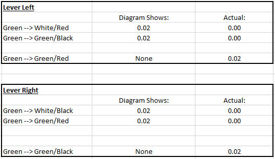
Just to make sure we're on the same page, here is a table showing my values compared to the values that show in your diagram. My values appear to be opposite (reverse of) what your diagram is showing:
-
@dhp123166 - I did some more testing this afternoon. When the lever in up (right signal) and put my multi-meter on the continuity setting, I am showing continuity between green-->white/black and green-->green/red. If I switch my multi-meter from the continuity setting to the Ohms setting, I get .00 on these connections, however if I put one probe on the green and one on the green/black or white/red (while the lever is up), then the Ohms reading is .20. The situation reverses if I have the lever down... meaning if I hold my probes on the green and green/red or white/black, I get .20 Ohms and .00 when the probes are on the green and white/red or green/black. This seems to be the reverse of what you are showing it should be in the diagram that you sent. Do you need me to send you a video showing this?
-
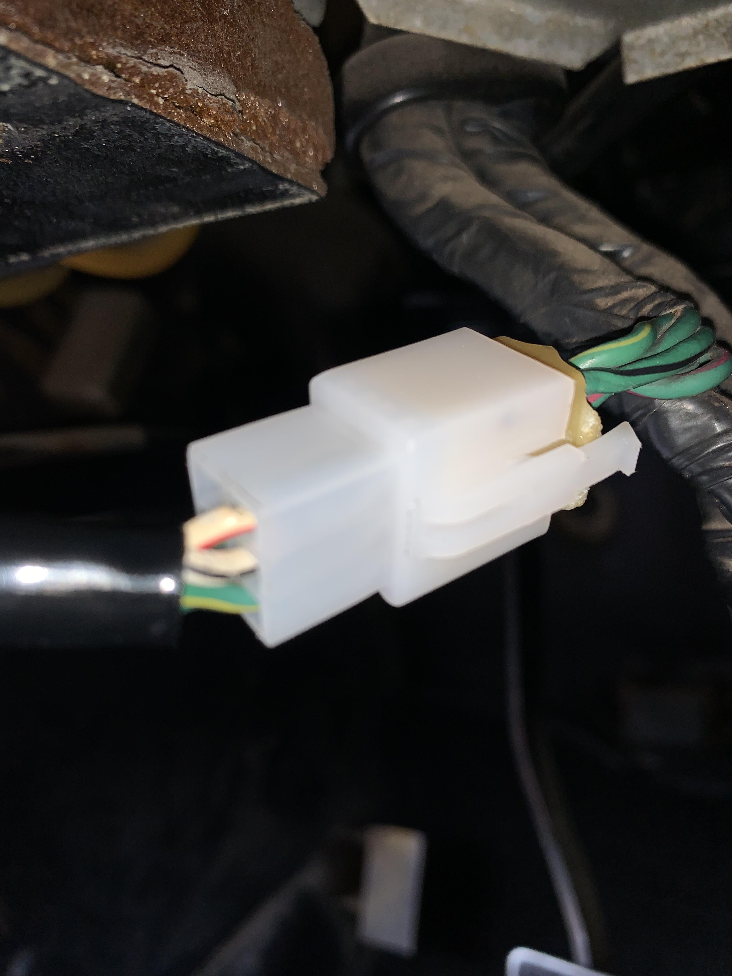
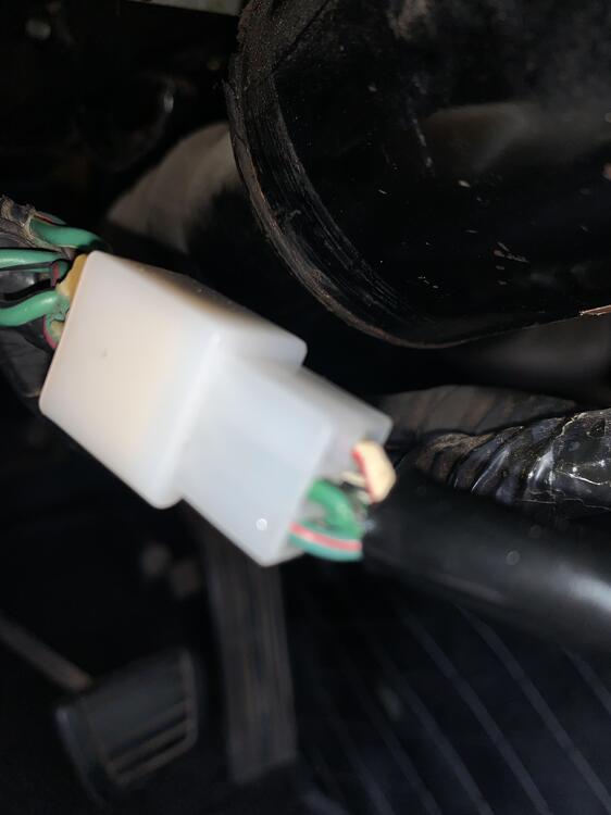
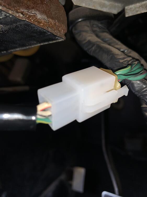
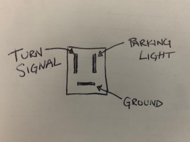
This is a drawing of the "female" side of the turn signal connector. My understanding is that the original turn signals consisted of 2 filaments and 3-wire (one wire for turn signal, one for the parking light, and one for ground). It seems as though the wiring to the turn signals is working properly since the hazards lights work... what am I missing? @dhp123166 - is it correct to assume that the new connector that you put on the turn signal switch should plug into the original stock connector or should I definitely replace the stock one with the new "female" connector that you included?
-
Thank you for the diagram @dhp123166 I only had a few minutes to do some testing today. I pulled the 5 pin connector and connected the test light directly to the pins on the connector. Here is a picture showing what I got: That being said the dash light did not blink/light when I connected the test light to these pins... not sure if it was supposed to or not. I connected the turn signals back into the connectors in the front of the car, plugged the switch connector back into the harness, but unfortunately I'm still not getting turn signals. Hazards are still working and I swapped the (brand new) relays from the turn signal to the hazards to ensure that I had a working relay on both. When I move the turn signal switch in either direction, I don't hear a click of the relay, however I do hear a click of the relay when I return the lever to the center which I thought was a little odd. The turn signal lights that I'm using for testing is just a single filament two wire light. Does anyone happen to know if the turn signals have to be a dual filament 3-wire light in order to work? or should the existing (2-wire) ones suffice? Any other suggestions/ideas for what to check? @dhp123166sent a new "female" end for the connector, so I'm going to try to replace the original one to see if that helps at all.
-
I have not had a chance to do any further testing yet. Hopefully today or tomorrow and I will write back soon. Thank you for not locking this thread. I would appreciate being able to write my findings here to get additional help/suggestions.
-
Thank you @SteveJ Once again @dhp123166 is putting words in my mouth. If you took a second to look at the picture you would see the caption from the WoodWorkerB site in the bottom left. Not to mention the fact that I never said this was my switch. How is my methodology half right? You’re not making any sense. I’m telling you that when the switch is either in the up or down position. Neither of the left or right blinker solder points are showing any voltage. I have tested all 4 points when the switch is up or down.
-
I have never suggested that the whole switch is defective. Please do not put words in my mouth. Not once have I ever said anything about the other functions (like hi/low beam) not working. And again, I have never spoken negatively about you. Why don't you tell everyone how I have repeatedly thanked you for your assistance and work on my switches. I simply came to this community/forum to ask for other suggestions. I never once mentioned who rebuilt the switches, so you can see that I never had an intention to single you out... you came out yourself to display that you were the one to rebuild them. When I am saying that the top 2 and bottom 2 wires are not showing any voltage, it does not matter the orientation of the switch... there will always be a top 2 wires and a bottom 2 wires and I was simply saying that I tested all 4 wires (when the lever is up or down) and none of them have voltage. That being said, when I made that comment, I was referring to the orientation showed in the following picture: You say my feeling are not facts, but I have owned 4 others 240z's and I'm just basing it off of how I remember the turn lever "feeling" in my past cars. Thank you for the information about the 2 small screws... I did not remember about those. I am not saying that your restoration process did not work. I am simply trying to get suggestions for how to resolve this issue and to find out ways to properly test the switch. I'm just trying to cover all of my bases. The car spent most of its life in Nevada so I'm not surprised by the cracking and fading that you spoke of. All that being said, I have not had the time to do any additional testing. As soon as I do, I will reply here with an update.
-
Ok thank you! I’ll give it a try tomorrow.