HusseinHolland
Free Member
-
Joined
-
Last visited
Everything posted by HusseinHolland
-
 For me, this can be cheap and effective. The point is, wiring is required. Anything remotely plug & play is going to cost more, since you are paying the creator. The only additional element is figuring out the settings for the timer relay.
 -
That's not cheaper than the $5 programmable relay. It still has to be (self) wired into the car, it's not plug & play
-
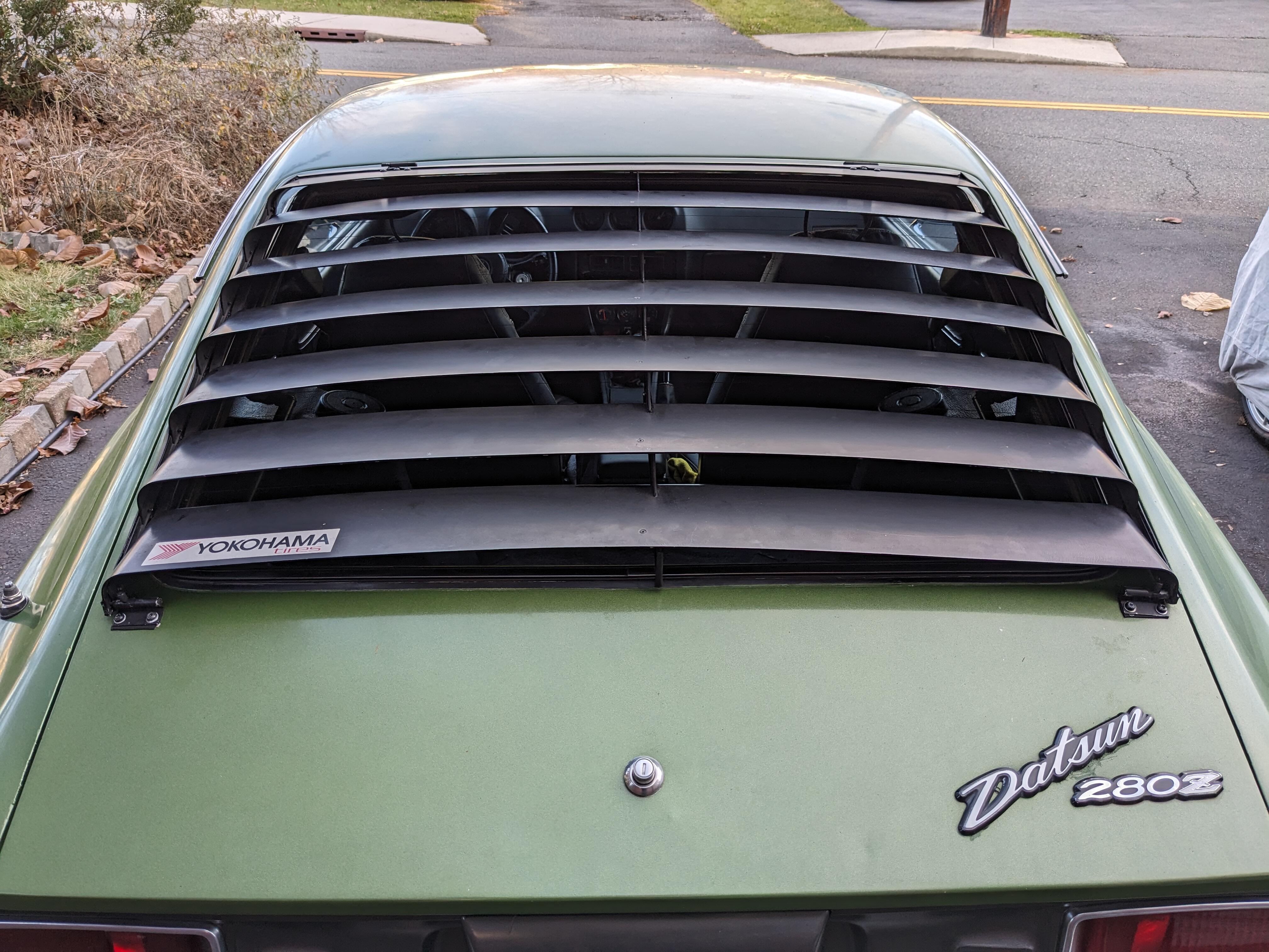
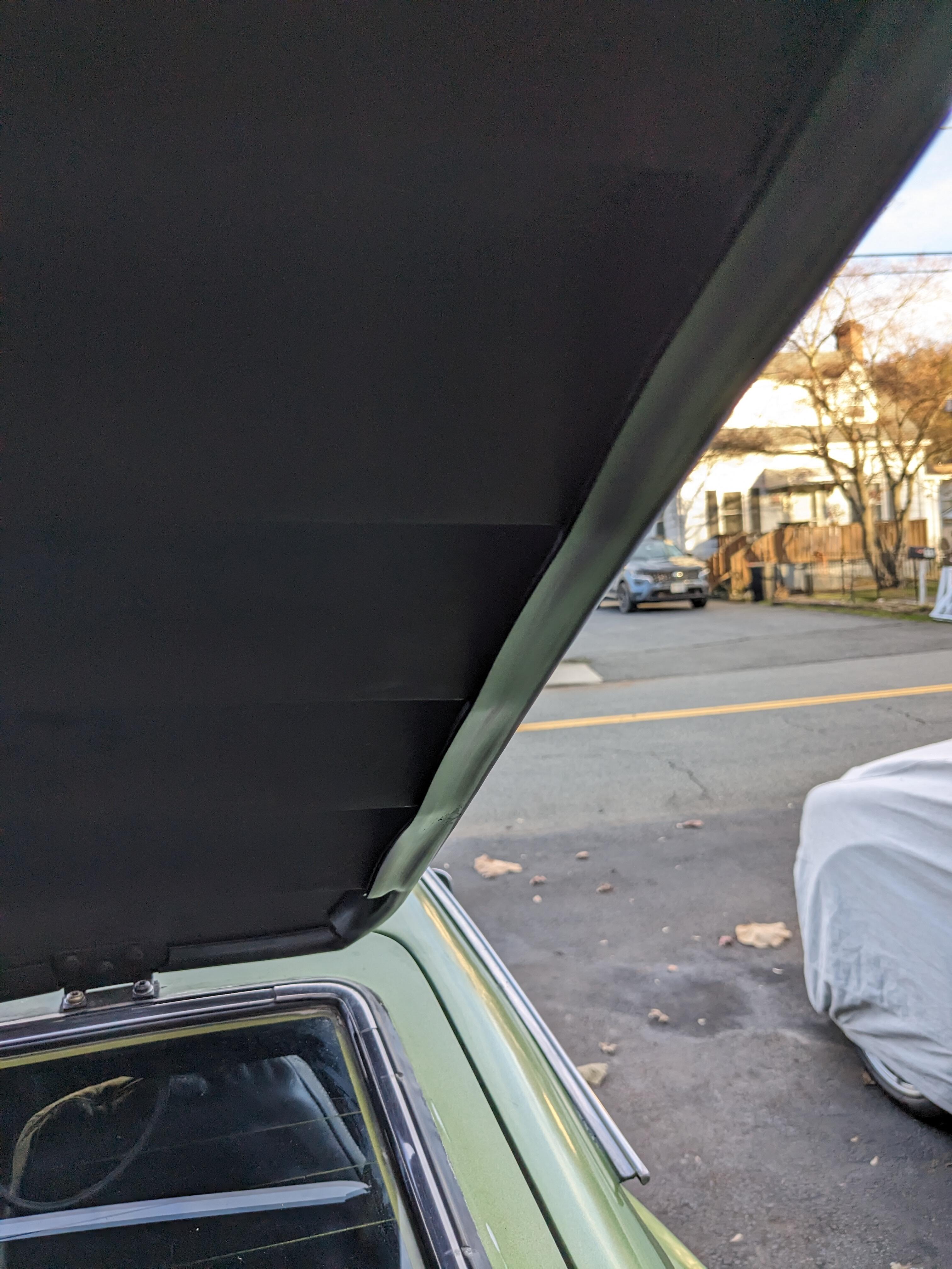
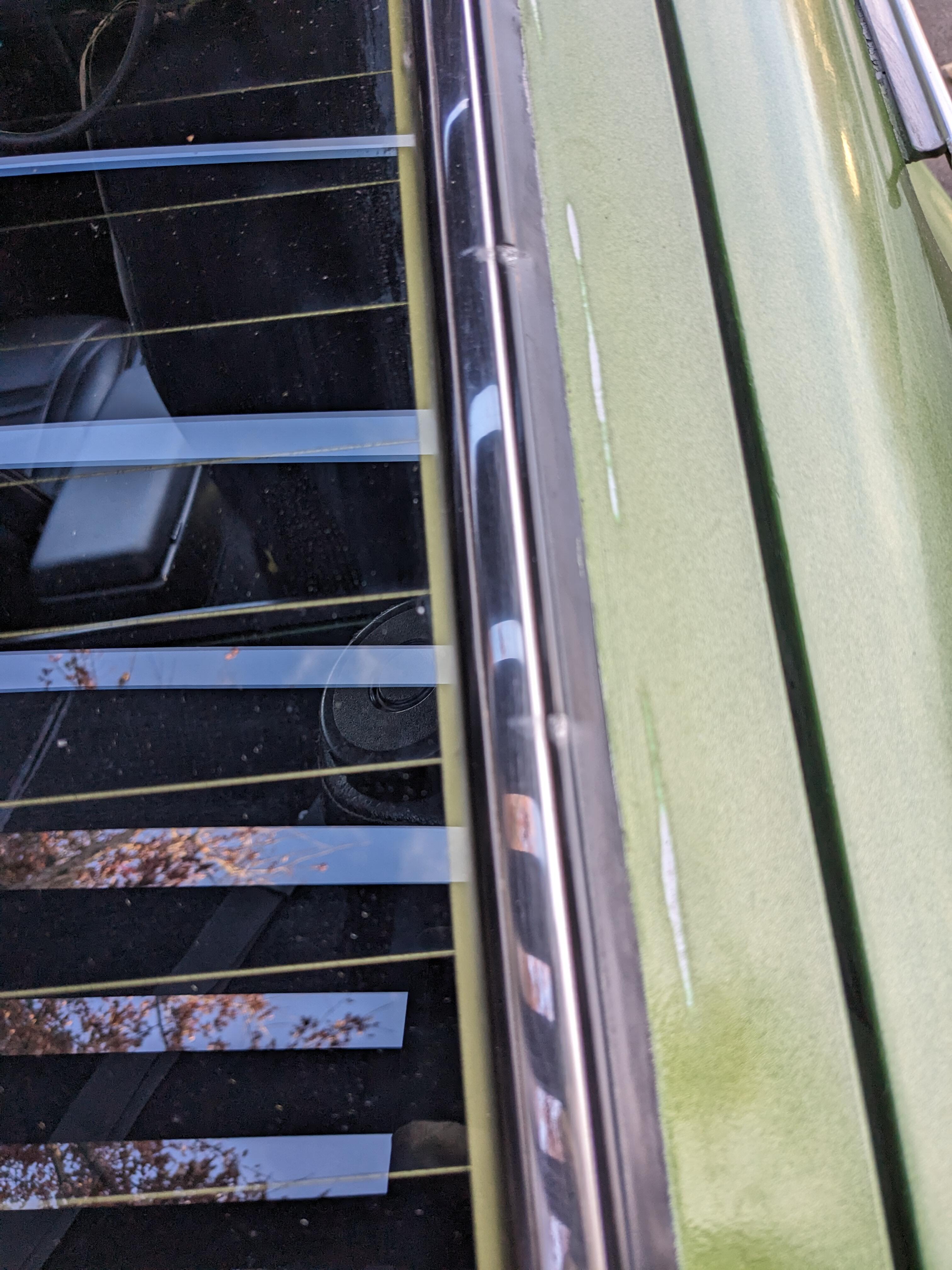
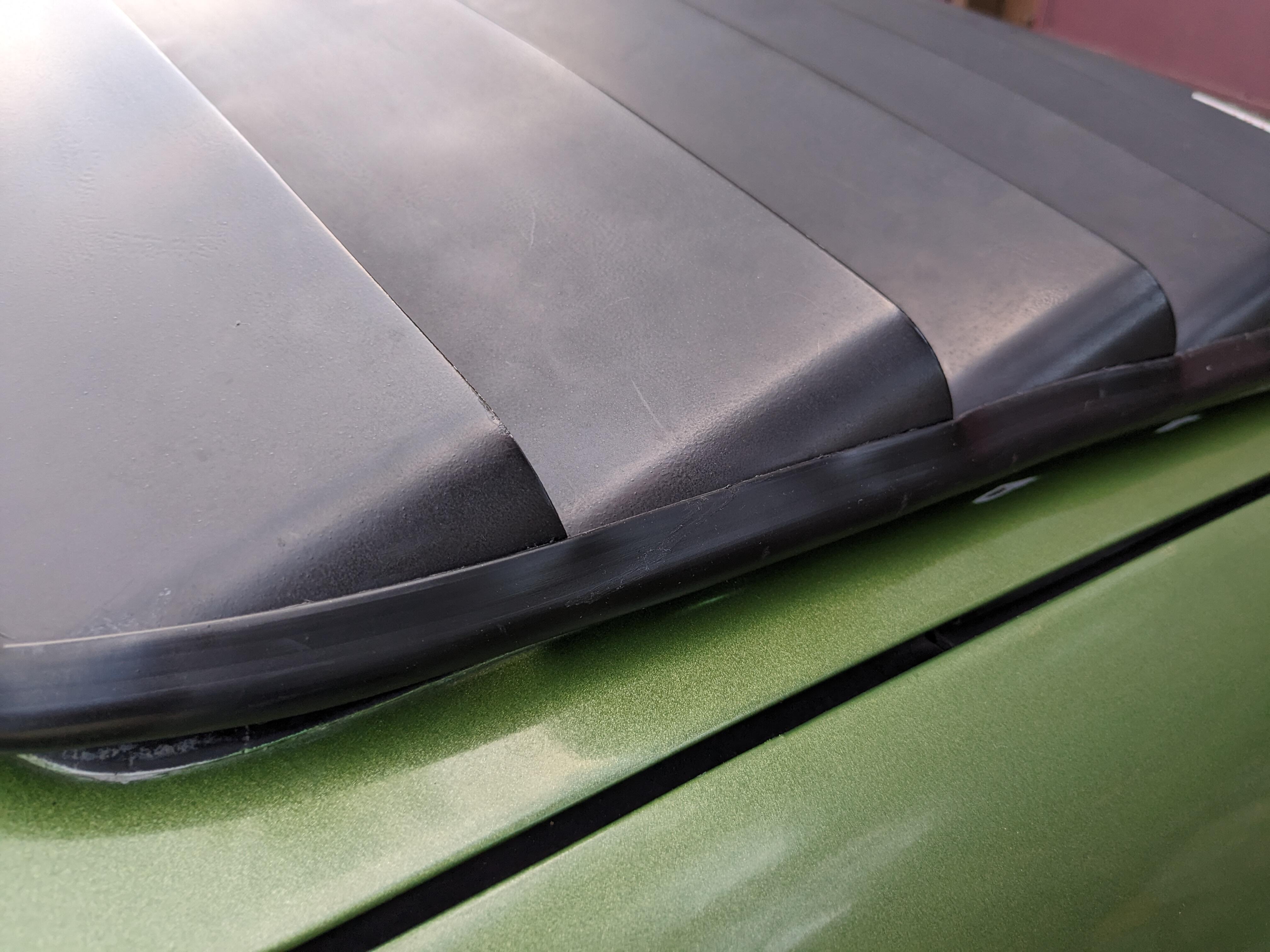
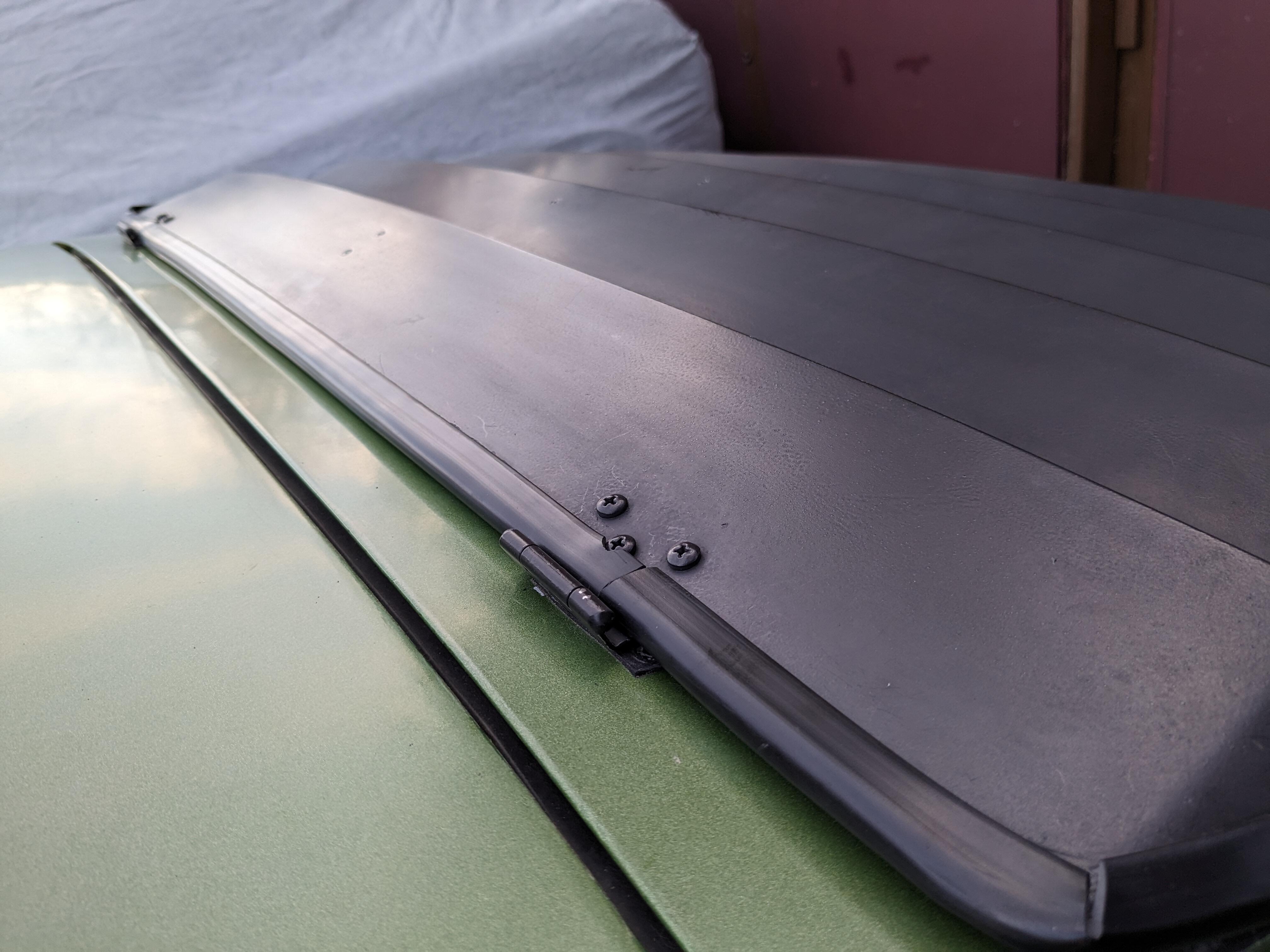
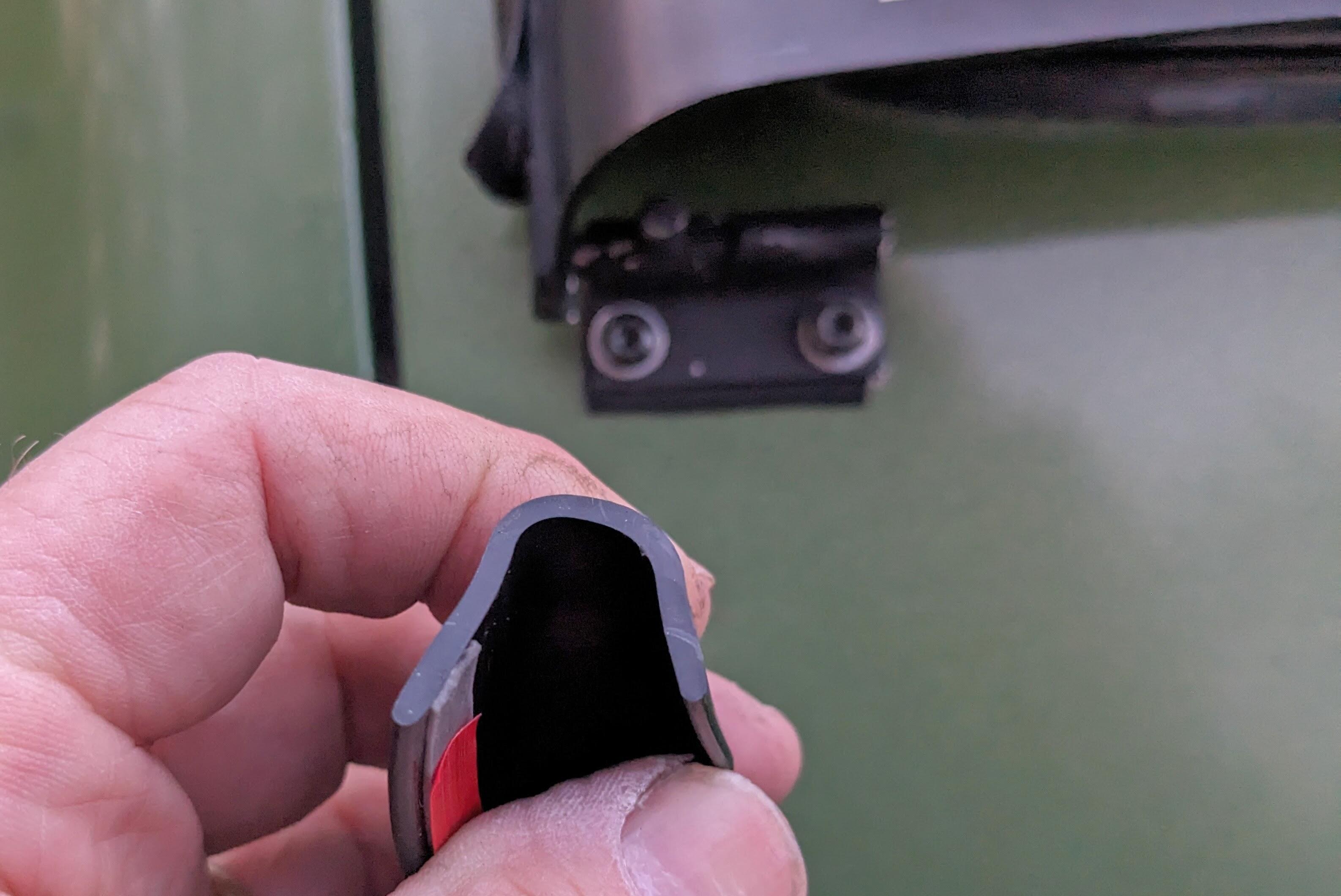
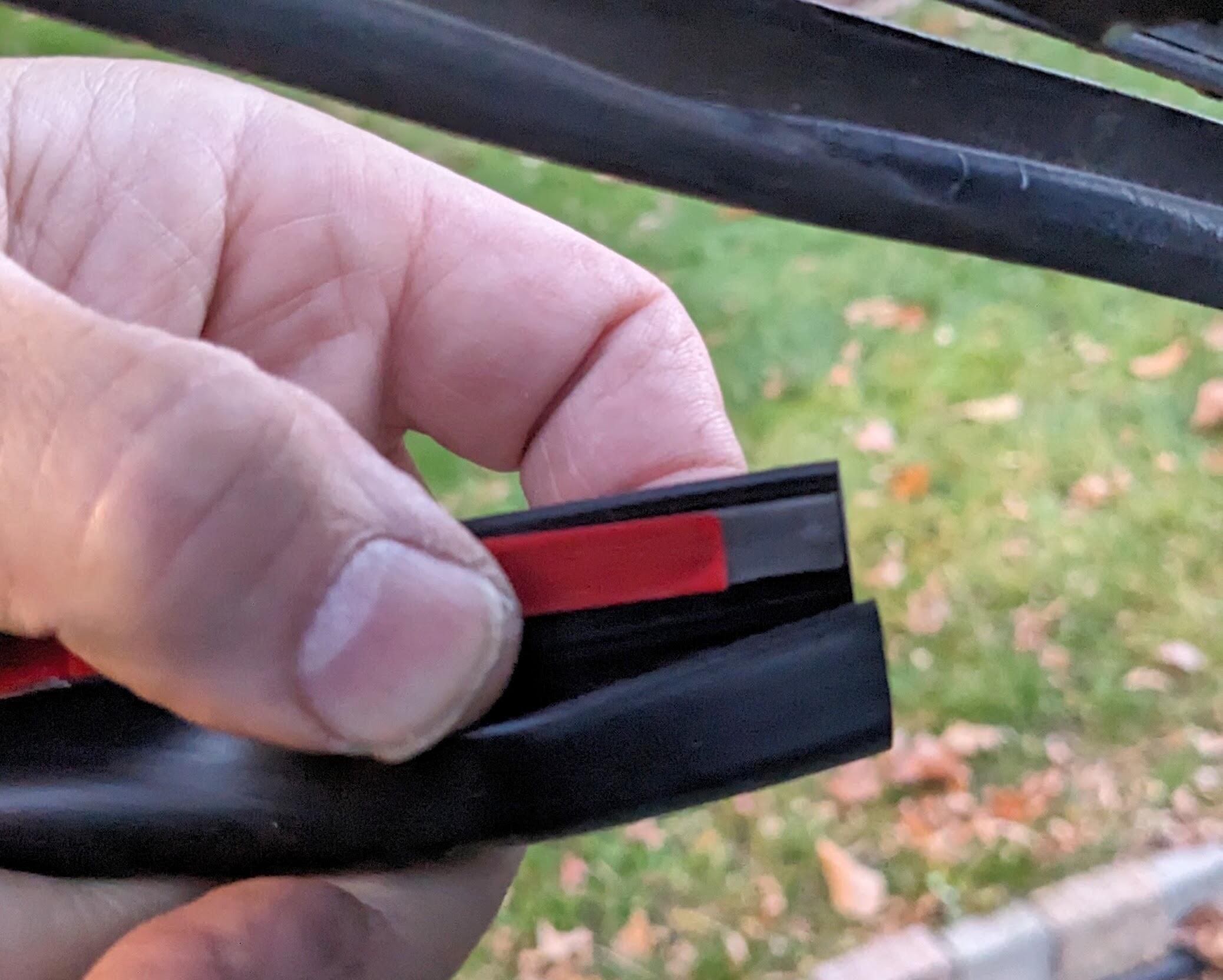
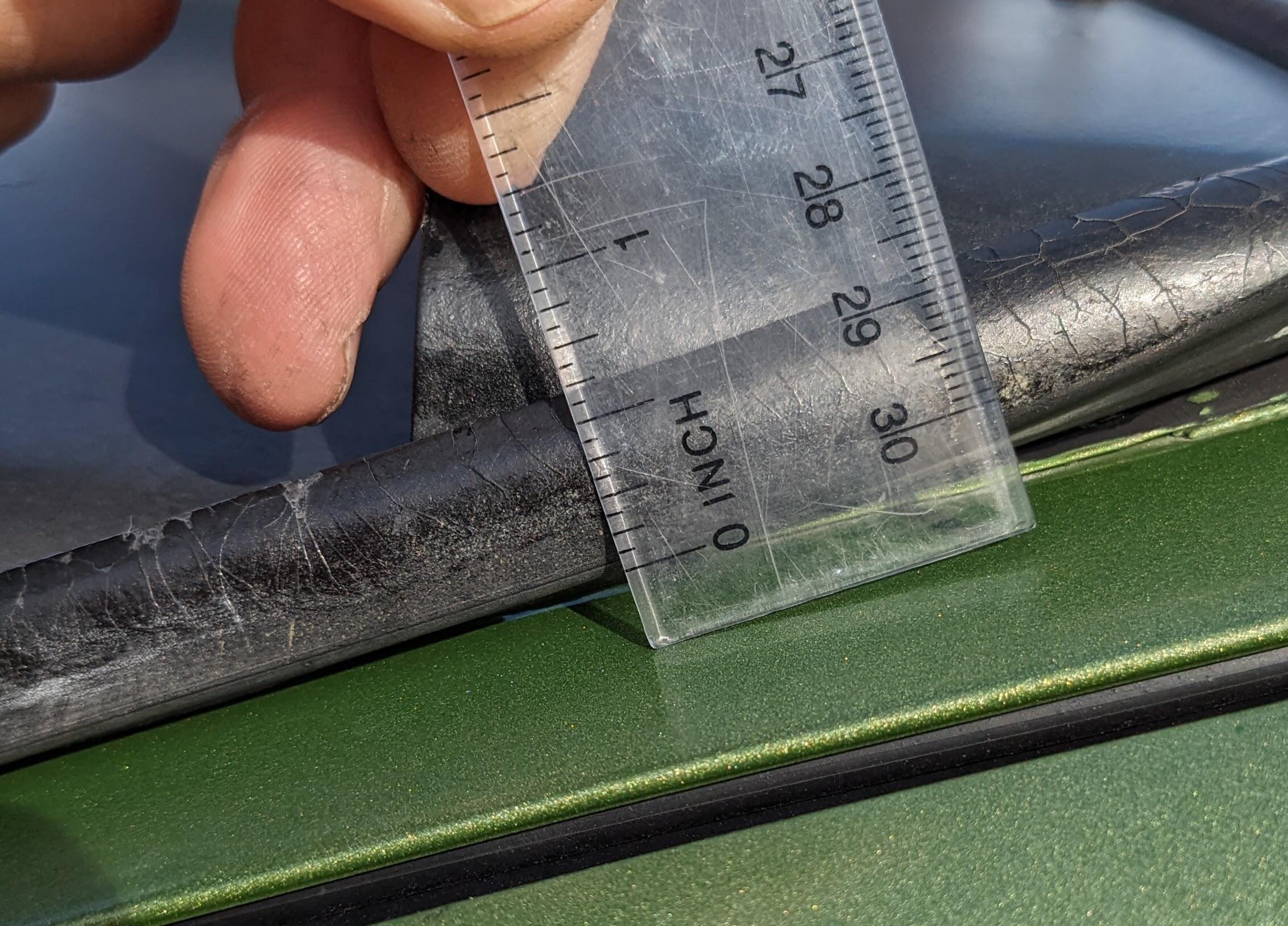
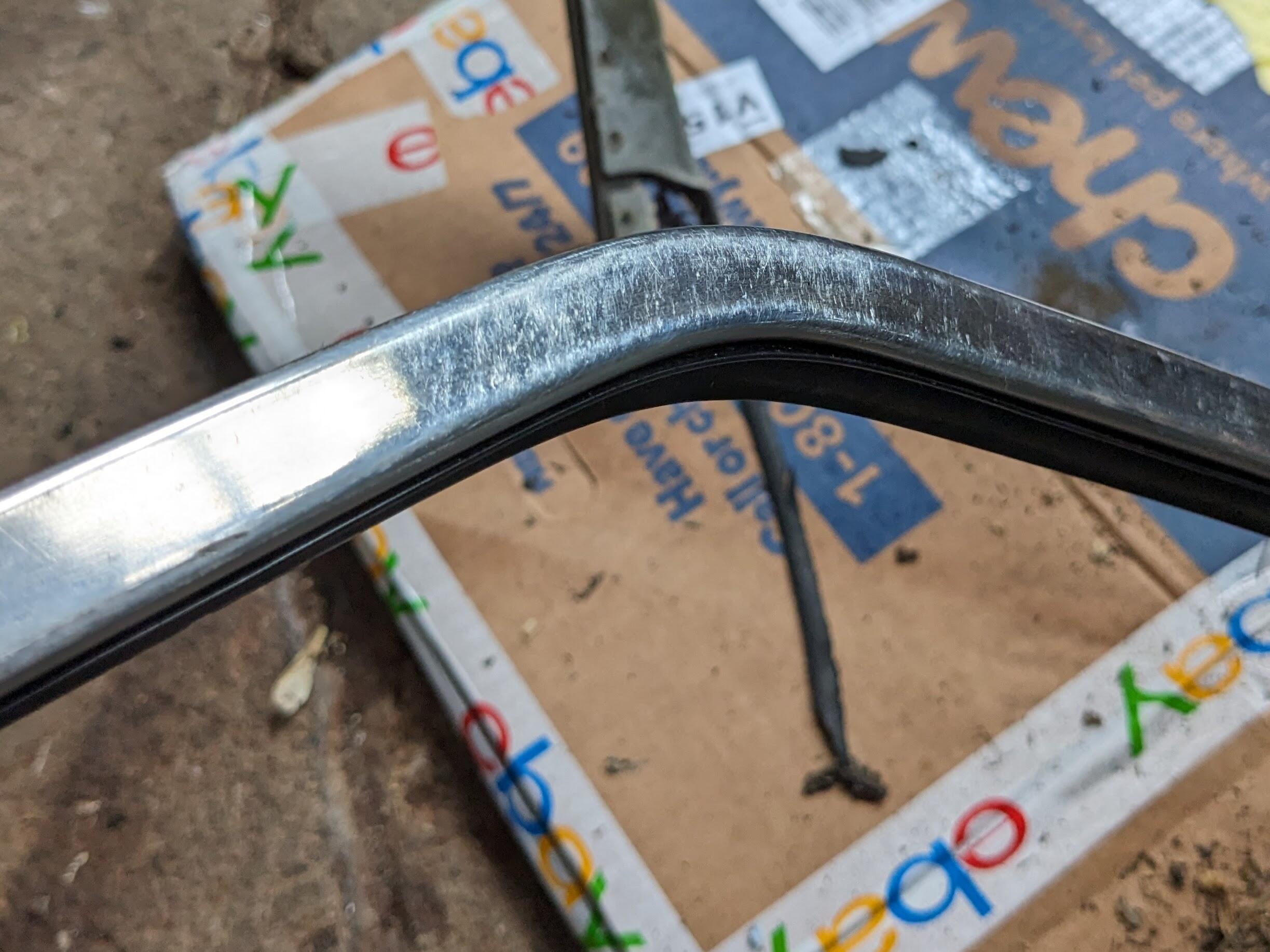
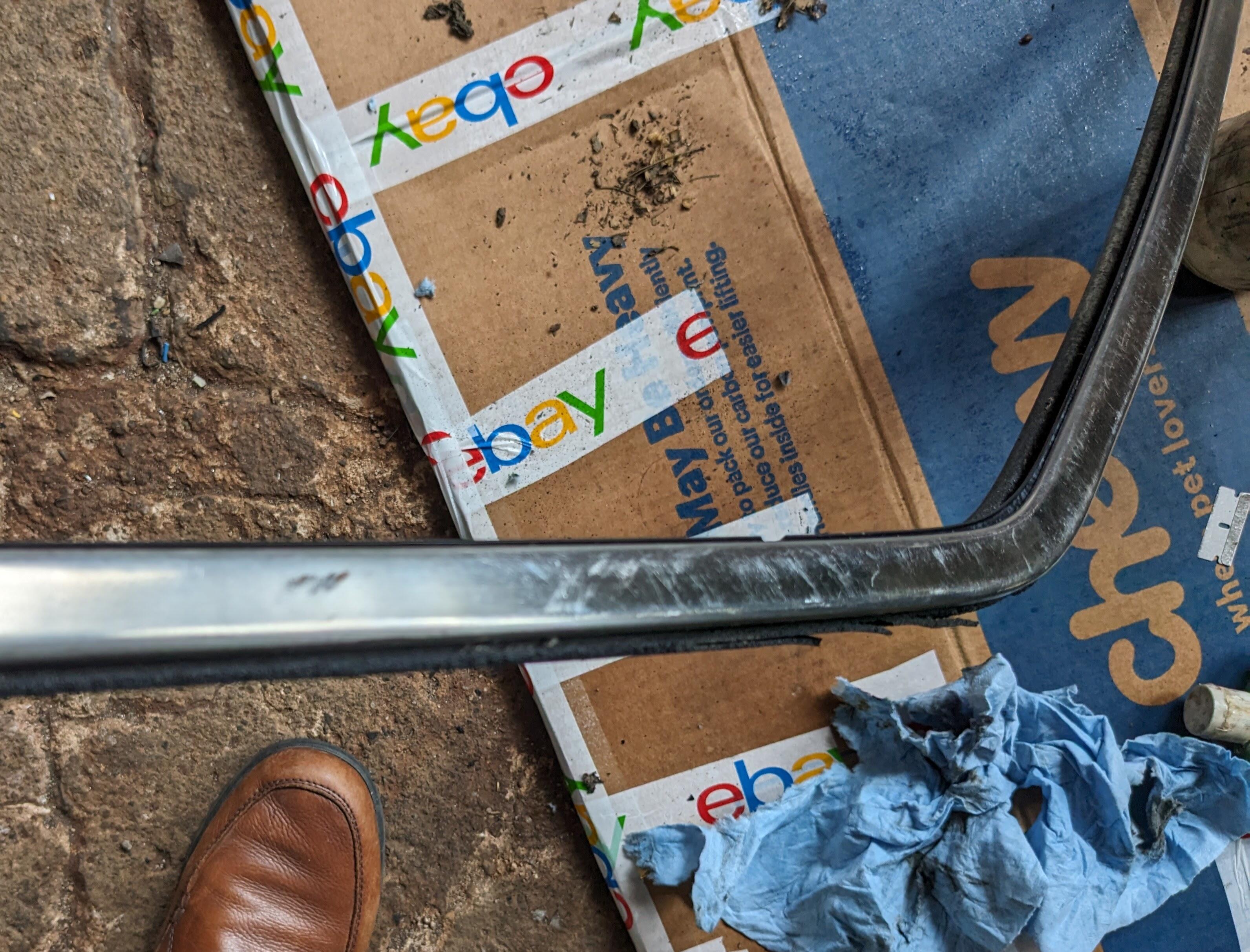
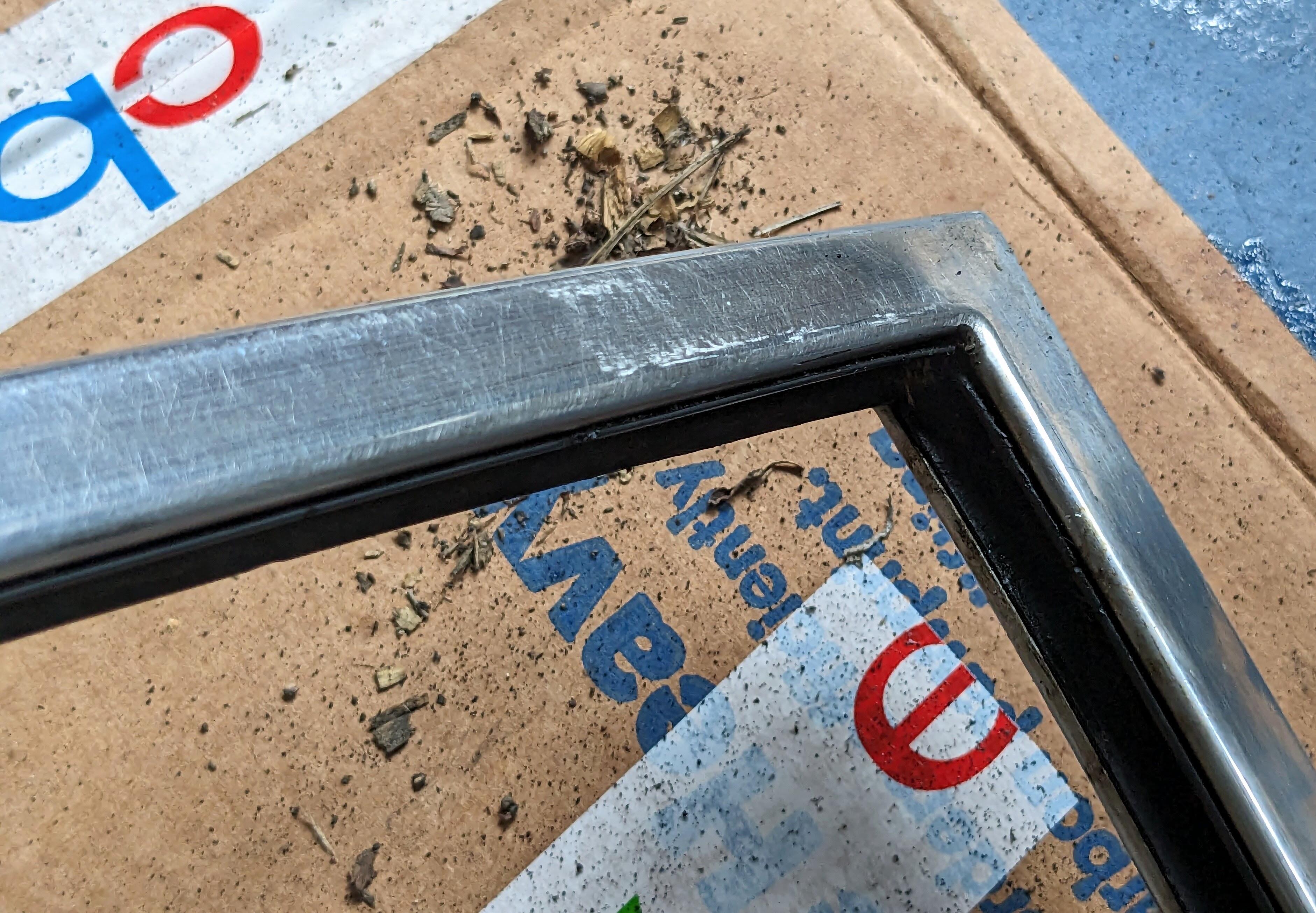
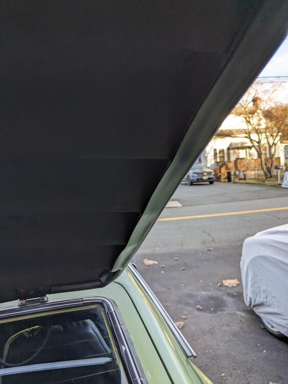
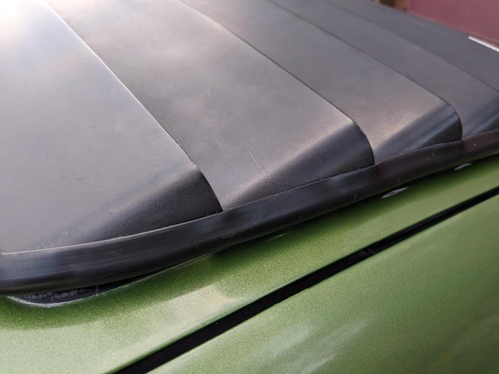
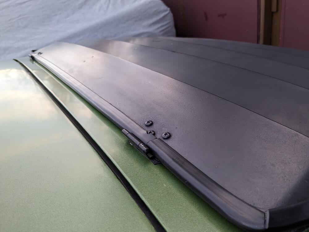
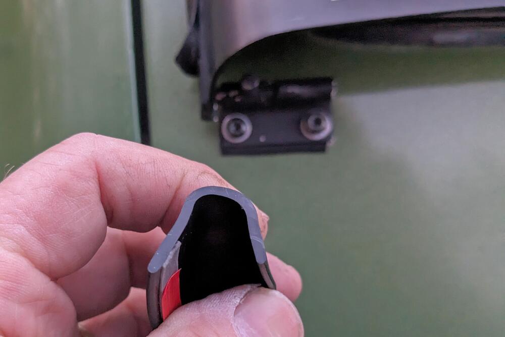
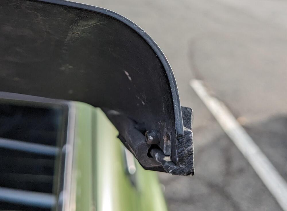
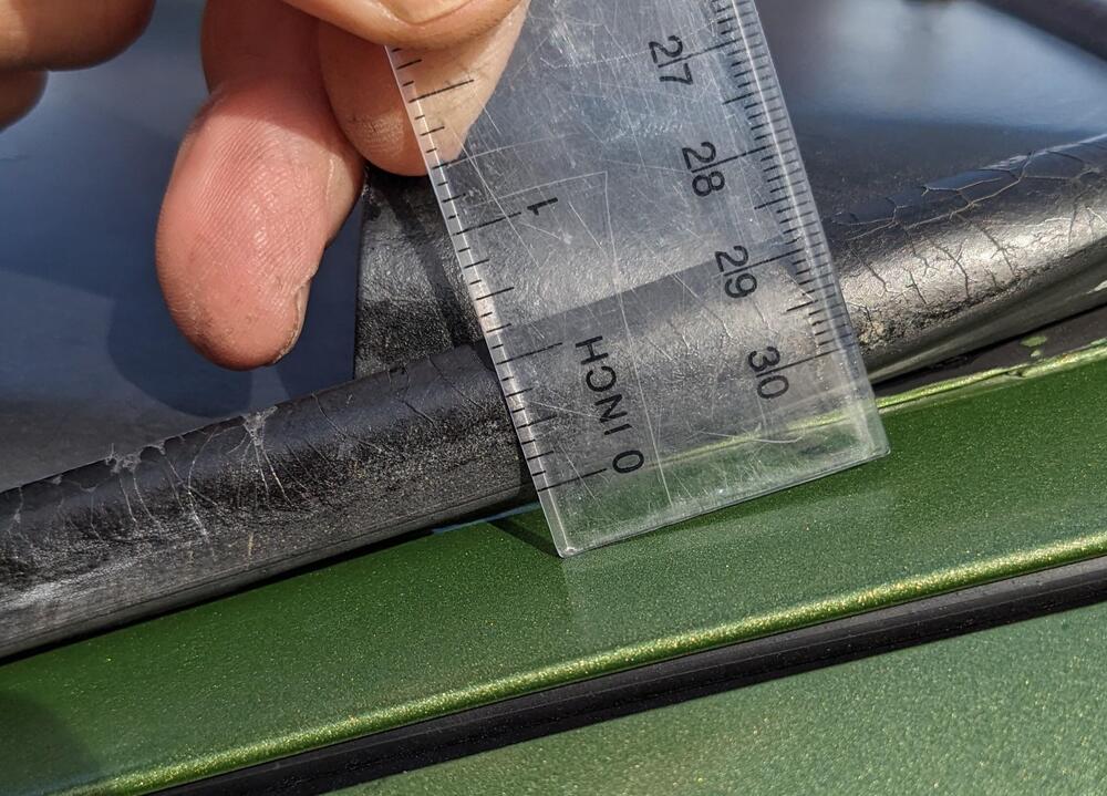
Redid the Louvre outer edging/seal The channel I bought worked, however it's not pliable to the extent of the original, so I had to cut slots where it wraps around at the top. I reversed it so the wide strip is on the inside, and works as a isolator to prevent the louvres from whacking the glass trim as it has been doing for the past 48(?) years


-
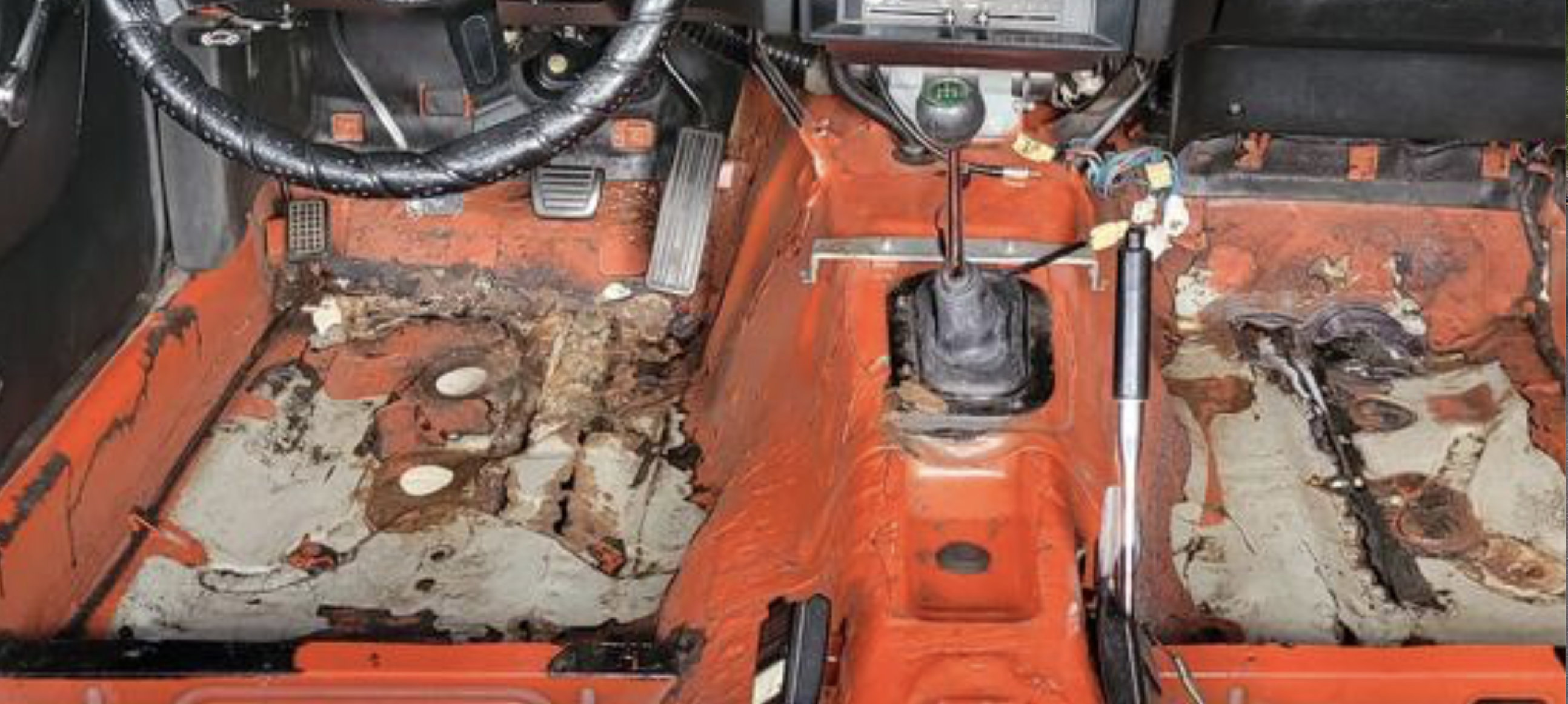
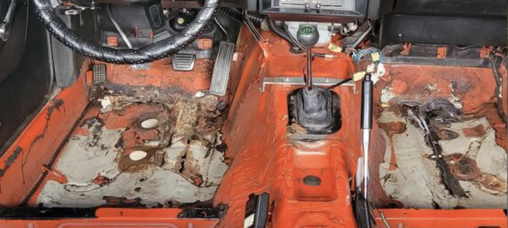
Do you have better quality/clear pics of the floor? The shots you posted are either unfocused or poor quality, so it's really hard to tell what's perforation & rust vs. shadow/tar etc., since we can't zoom in & get any clarification. For the underside, unless you remove the undercoat you mentioned as being added, you are not going to know how extensive the rot is. It's been my experience it's always worse than what is apparent. In this pic, it looks like the rust & perforation goes all the way across the from of the floor beneath the pedals. In one of the other pics, it looks like coffee can under the seat rail. If you are doing it yourself, and have some prior MIG/TIG experience, it's really just a question of stripping all the undercoat, cutting out all the obvious rust back to clean metal, then evaluate whether you can patch or if you need to replace entire panels. The metal used on these seems to be very thin gauge, I'm surprised how easily the outer panel flex on my 75.
-
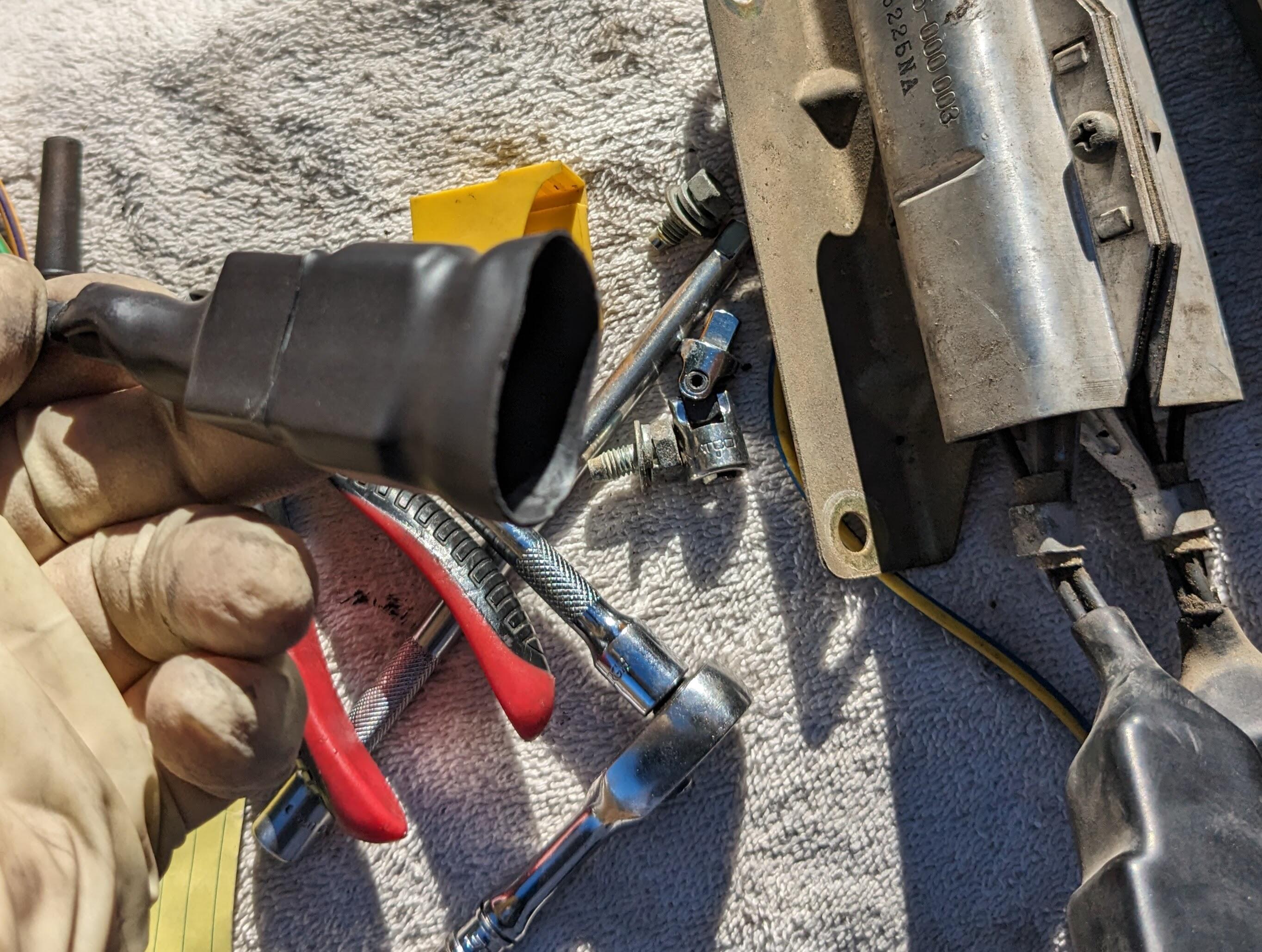
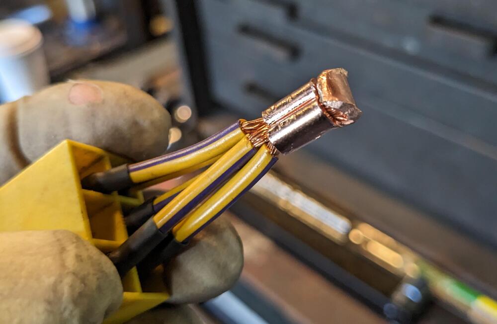
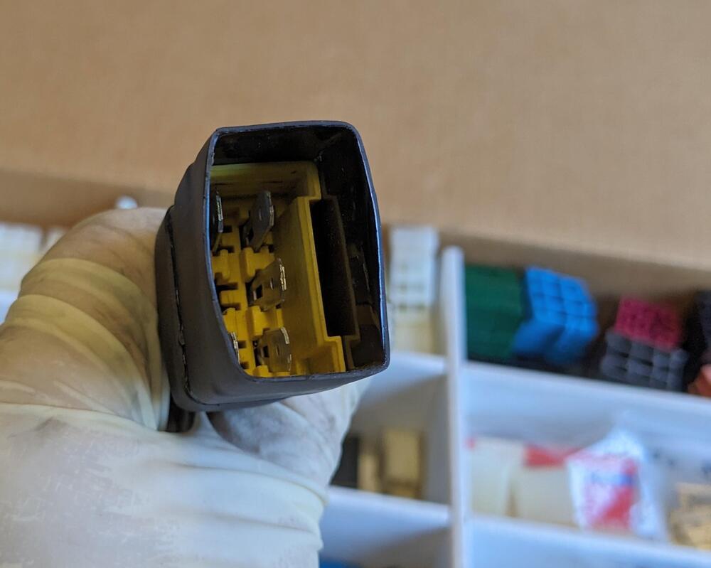
I'm going to add the relay - it's just a bit of a PITA to work with the relay end of the FI harness in the space under the dash. I really should have thought about this while the dash was out. Hindsight is always 20/20. I'm going to add a bridge harness to take the AFM pump trigger, run it through the timer relay, then back to the factory relay. So, I need to extract the trigger wire from the existing relay socket. The constant and switched power for the timer can also be drawn from the main relay, to avoid running lengths of new harness from other sources. It would be possible to make an entirely plug & play insert to redirect as needed from the factory relay sockets, however that would end up occupying much more space up under there, which I really don't have now that I added the 2 adjustable flasher relays. Working on my back and/or twisted up under the dash is not good for my lower back issues, so in part I am avoiding it for that reason. I will get to it eventually.
-
Much better viewing inside. Got any pics of the underside where those rails & floor meet the bulkhead? The type of issue that can arise is where there are multiple overlapping panels. This was on my X1/9 Once I removed that perforated forward section: multiple layers to address. That would be my concern with your level of visible floor rot When you patch panels you have to consider how the new & old are joined - butt, lap, etc., you want to make sure you don't create water traps. In the end, I cut pretty much all of it out, so I could fit the panel inside at the leading and inner edge and under/outside along the rocker & seat frame area, to match the original flow of the panel welds. You do want to investigate what path makes the most sense. Your DS looks like most of it should go, depending on what it looks like under the seat frame rail....
-
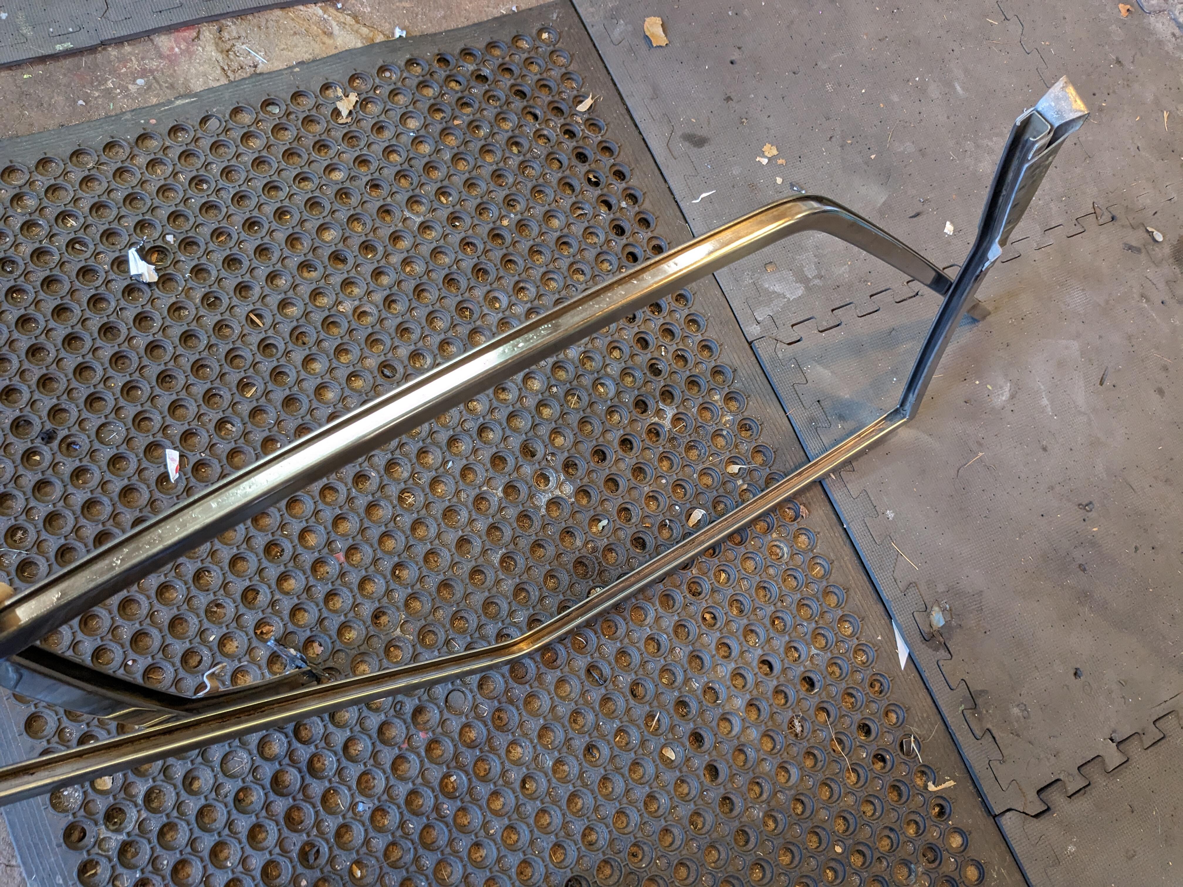
ProTunerZ is sending me another rail. They said they will send one with a more obvious chamfer, as they do seem to be variations. Apparently none of them have a significant chamfer on the ORB-6 port, and they said I am the first one to indicate it is a problem. The "chamfer" such as it is on mine is not uniform, and where the thread is visible close to the surface is where the o-ring pushed out. Perhaps most ppl block it off instead of using it as an active port? I dunno. Anyway, I'll swap it out when the new one arrives. The Allen heads are where the rail is bolted to the provided standoff brackets. The website illustrates the old brackets, which apparently bolted to the head/manifold studs (Yuk) - the new version bolts to the stock rail mount points.
-
Dang. That layered rust is giving me PTSD. Even my X1/9 rot pales in comparison. How do you get through all those layers without completely removing everything inside & out?
-
Finally found a rubber seal that should work to refurbish the rear hatch Louvre. Also found a thin U-channel that will work for the center ridge.

-
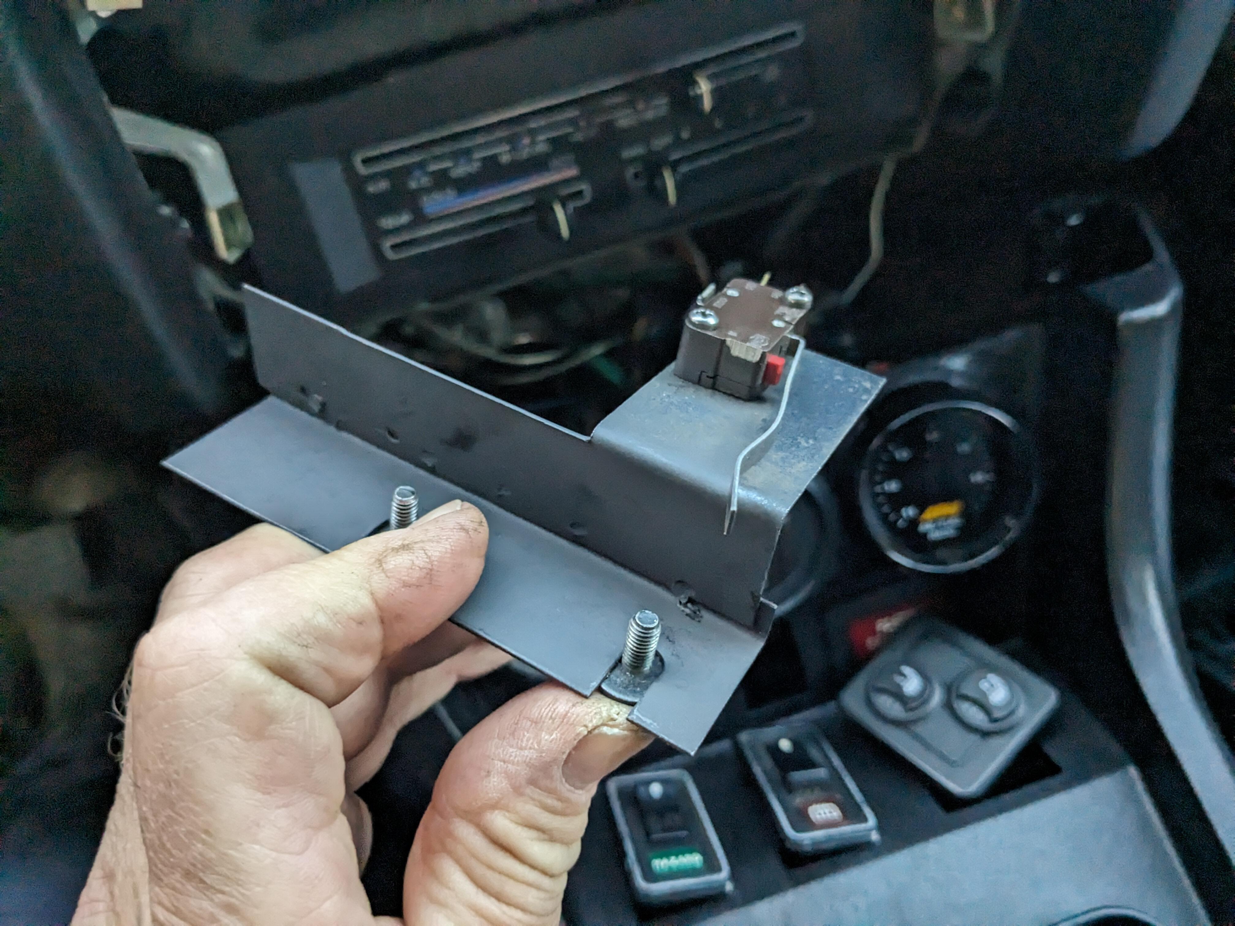
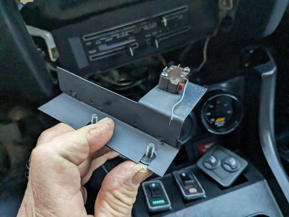
Finally figured out how I can use all the 5 speed settings of the Volvo resistor pack. Been looking for a 4 speed switch without any success, ones I did buy listed as 4 speed, were not so. I decided to add one of the micro switches originally installed with the aftermarket AC. Modified the supplied bracket (sectioned, spot welded to correct the offset) so the microswitch lever sits behind the fan speed switch in the off position, and turns on between off & first speed detent
-
All the others I've seen are $80 or more, so it's still cheaper even with the higher shipping
-
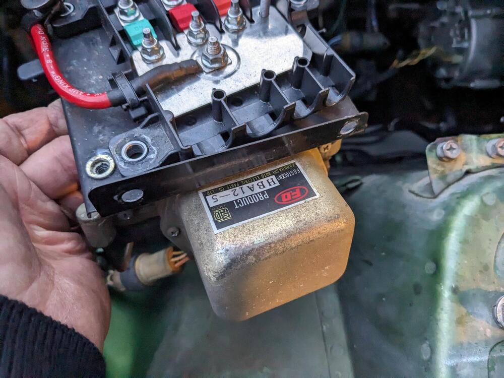
Nice find - I searched for V/regs , and that one did not come up. For the price, I think I'll just get one. As I mentioned, mine has pitted contacts, so even with cleaning it is not perfect
-
Standard Motor Parts, from RA. Actual part is unbranded
-
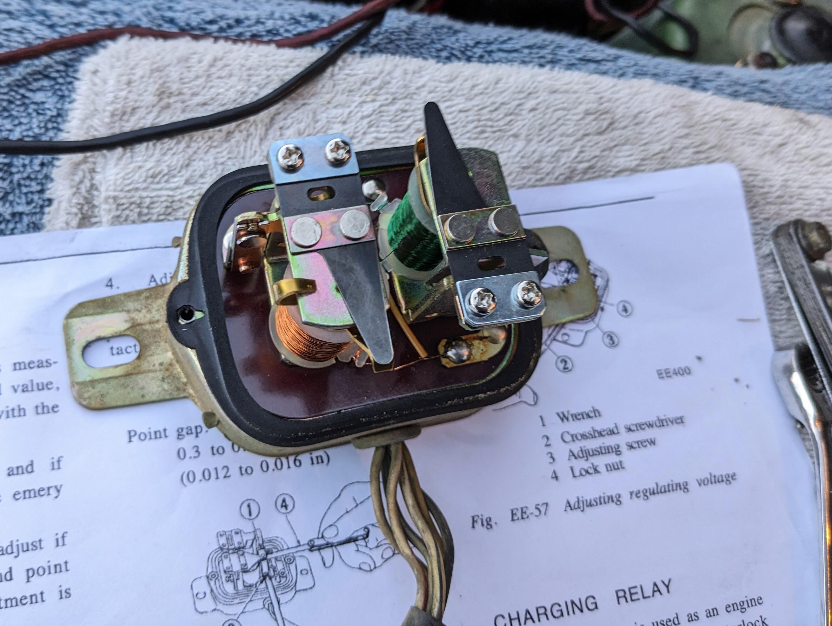
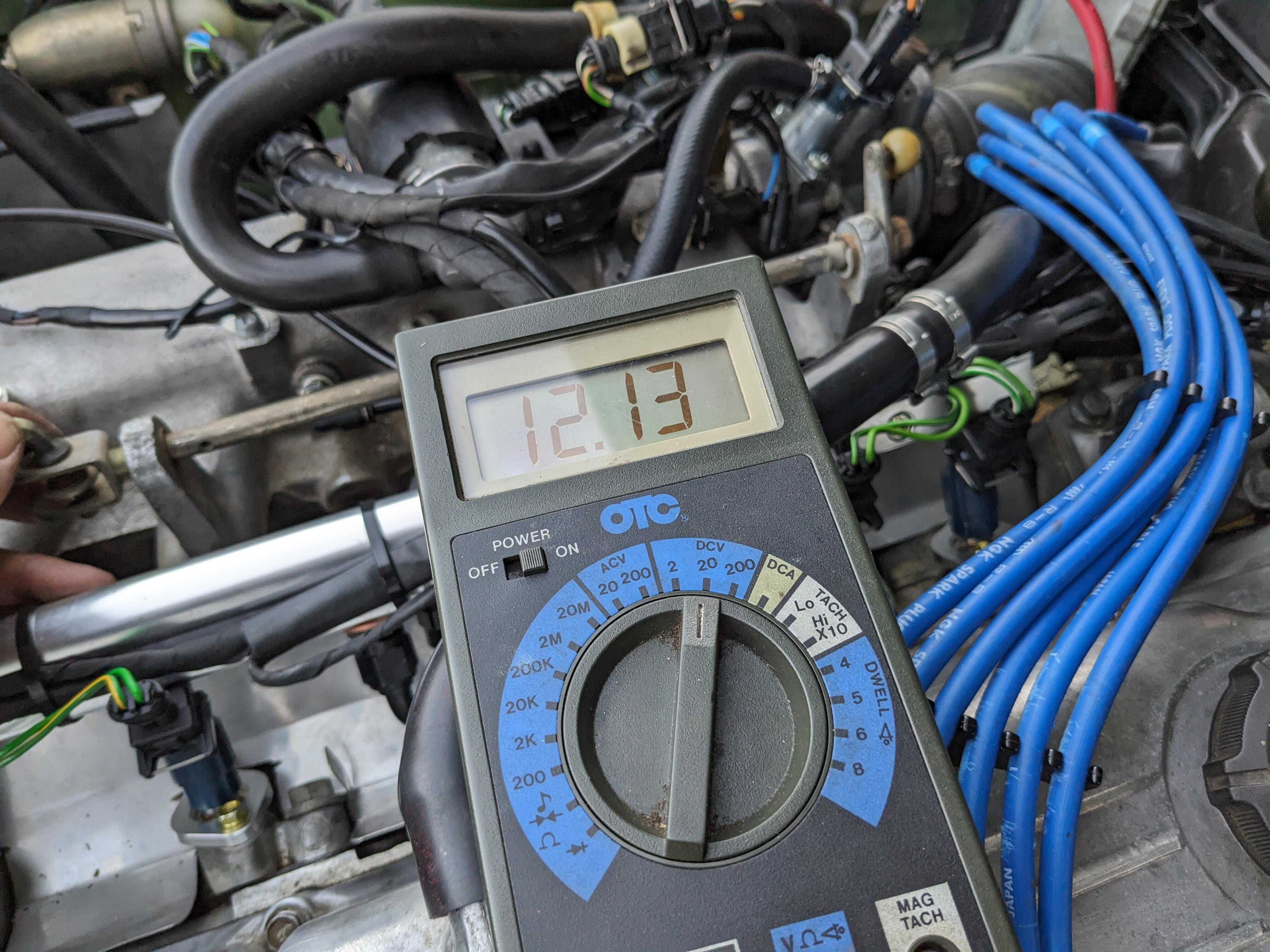
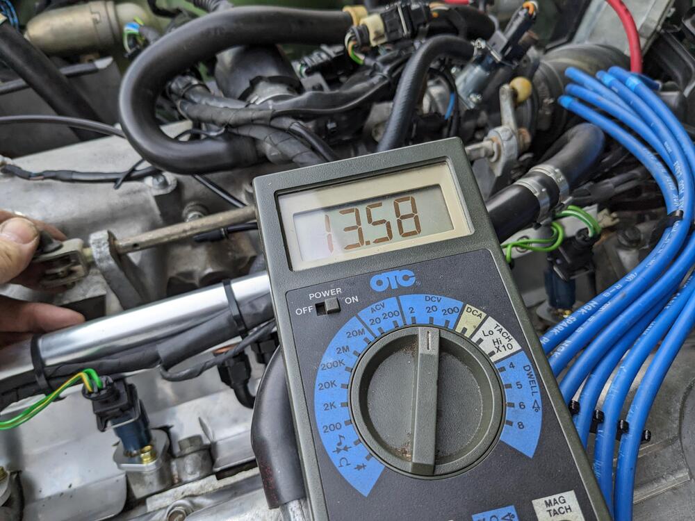
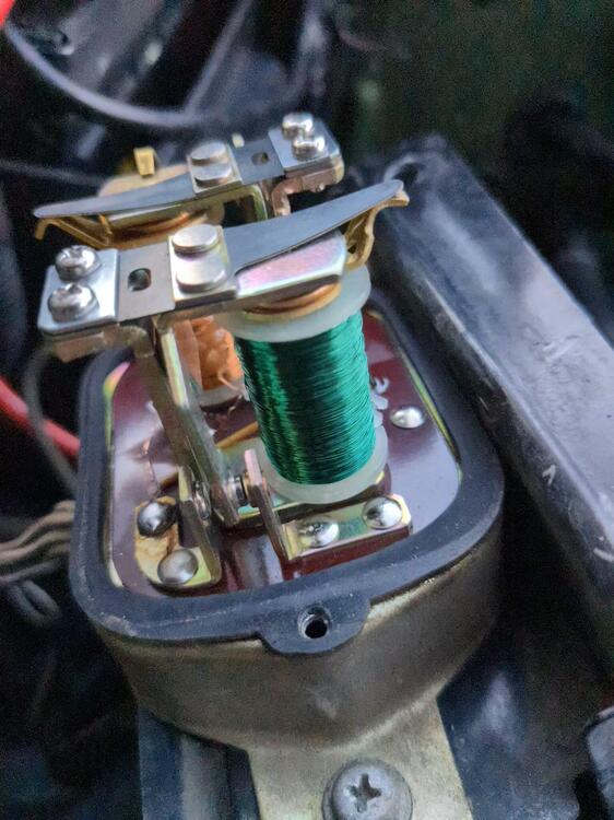
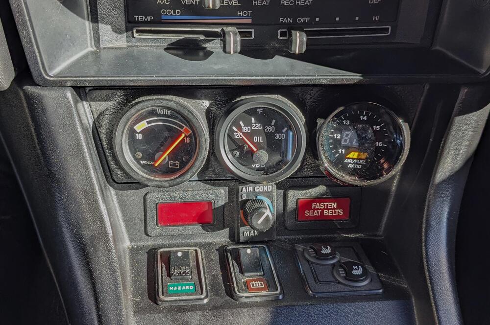
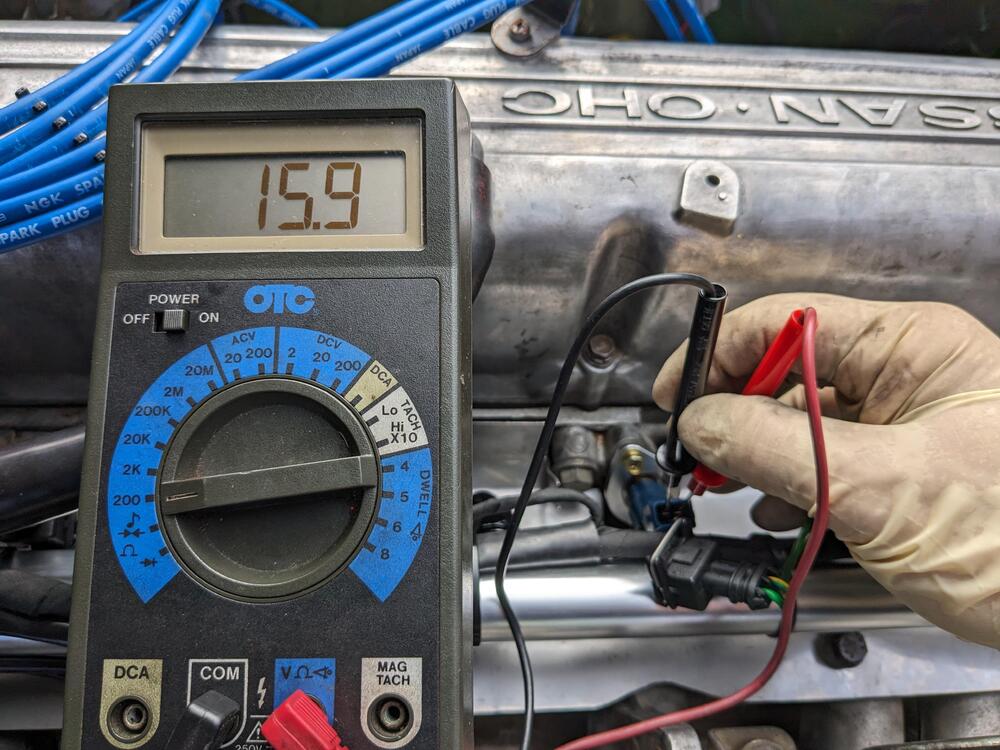
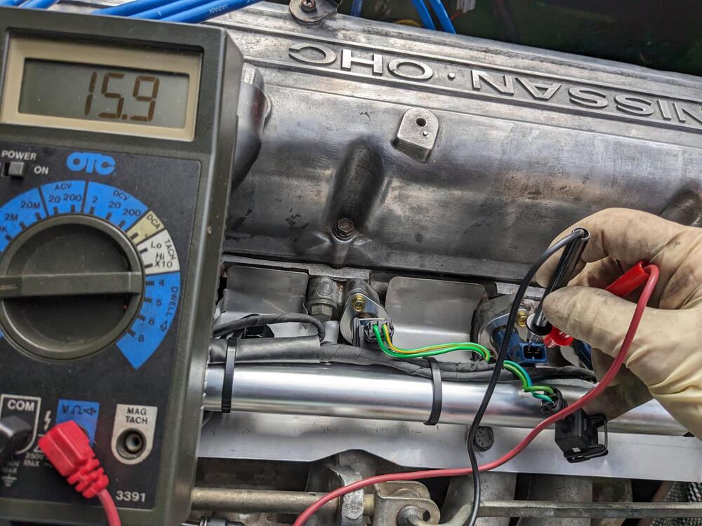
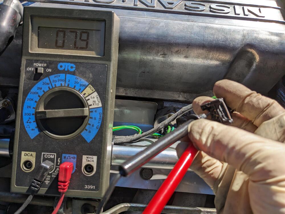
Adding to this rather than start a new similar thread. My system puts out 15.5-16v as soon as the engine is revved over 2500rpm, regardless of load. Sometimes it spikes to that off idle. Seems hair-raising to me. I'm used to 14.1-14.5V being optimal on my Swedish & Italian cars. This was around 1800rpm I read how to adjust it in the service manual, however mine did not match the diagrams. I had to adjust the point gap by loosening the two top screws. It was unclear which side of the points was supposed to be checked @ .012". After initial adjustment I was only getting 12V any any rpm, so I decided to adjust it while running - that way I was able to check idle & high rpm values for consistency. I settled on 13.8-14.5 range, as tweaking it outside that just need up with either too low or back to 16V range. My points do have some pitting, so I sanded them to remove the peaks at least. core gap on left, point gap on right Point gap seems to be the left side standoff on mine. When I set the larger gap on the right side, it didn't charge at all initial adjust final setting - goes from this to about 14.5-7 max. Seems good to me


-
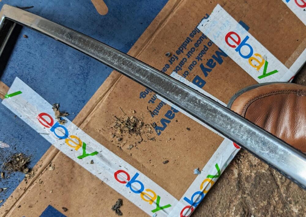
I did see that - however the chrome on mine is burnished/marred where they sanded the car for paint 30 years ago. I don't throw things away, so I was planning on saving the old ones in case the new construction doesn't past muster.
-
ZcarDepot
-
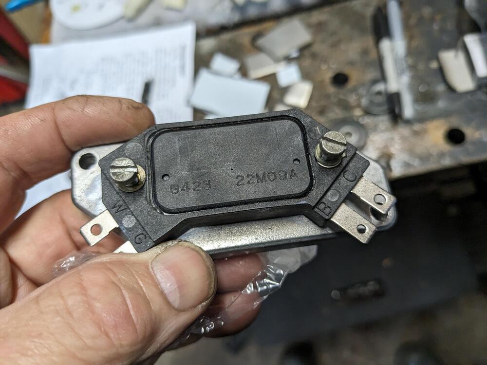
To conclude this for me at least, using the GM-branded module, the symptom has not returned. I've been driving and commuting in the car everyday (except a couple of rainy days) and have had no break up / cut out. Other issues, but those are fueling related 🤪
-
They are, but clearly they can still rust depending on the grade. Mine have rust "powder" on the inner surface that presses against the door seal.
-
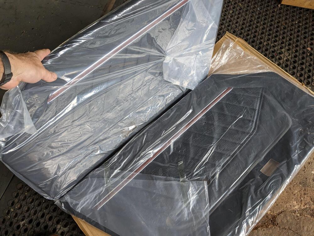
New panels came - not going to install them until I get the sashes done
-
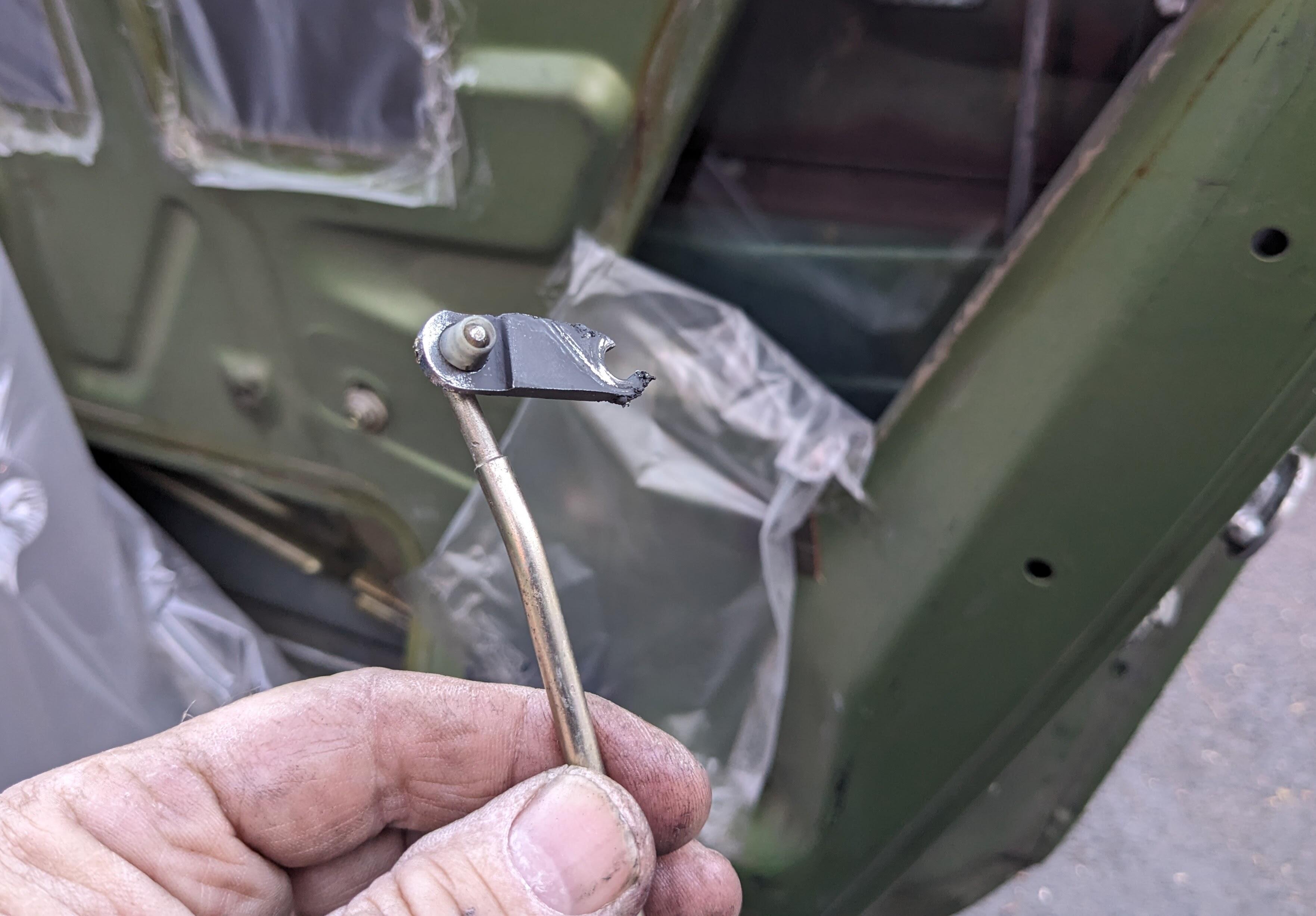
Also - took the pass door card back off to get to the outer handle link rod - I though that was ht issue - turns out the door handle lever snapped off I'll have to order new handles

-
Cleaned up the 78 window frames (sashes) I bought. Certainly not 'excellent' condition - multiple scratches from storage. Hopefully I can polish most of them out, never tried before. He didn't pack them with any buffer between them either. Have to figure what compound may work without removing the coat. My existing frames are worn thin & have surface rust on the seal surface, which is why I want to replace them Stripped all the old inner & outer seals


-
10-11 is just dumping gas. Even with a high pressure Turbo, you really don't want much under 12 for good power. I was mainly checking that I had uniform values at all the injector sockets, since they all originate from those 2 wires that feed the ballast. Just to be clear - the AFR's weren't on target with the ballast in place - I had the lean condition at warm idle, and some unevenness under load conditions. It did feel better than the stock injectors, but now it feels really smooth by comparison, so I'd say removing the ballast is wise with high impedance injectors.
-
Warm idle, AFR's are now steady 14.7-14.8, with the pot set back at .8 (800ohm). The last few days, I had to enriched the pot value to 1, 1.1 1k-1100ohm) to get the AFR back down form 16.3-16.7 YouTube Vid EDIT - test driving under varied conditions, including WOT - AFR's are good across the board, until I go WOT, then it's way too rich (high 10's-11), so I reset the WOT TPS contact so it's not in effect until 70-75% YouTube Vid
-
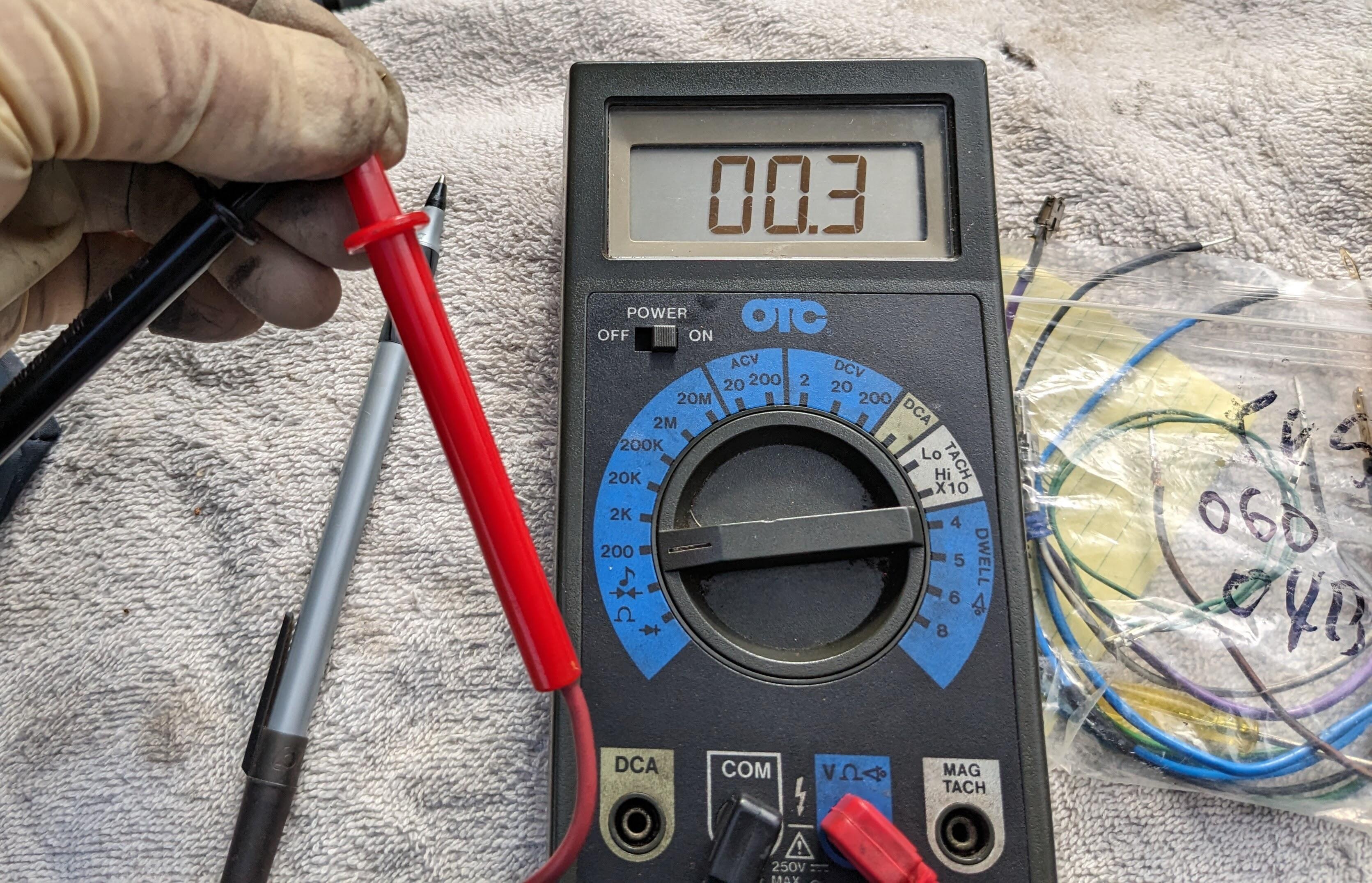
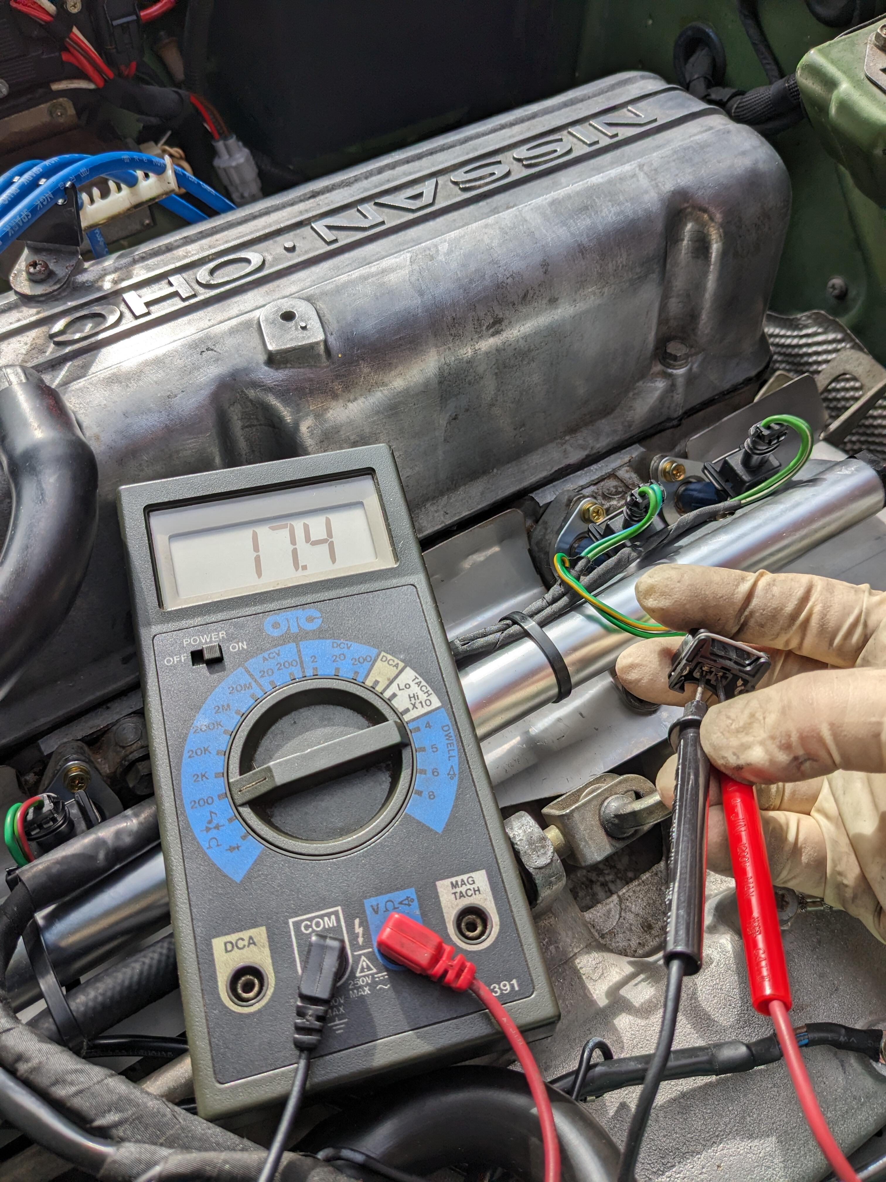
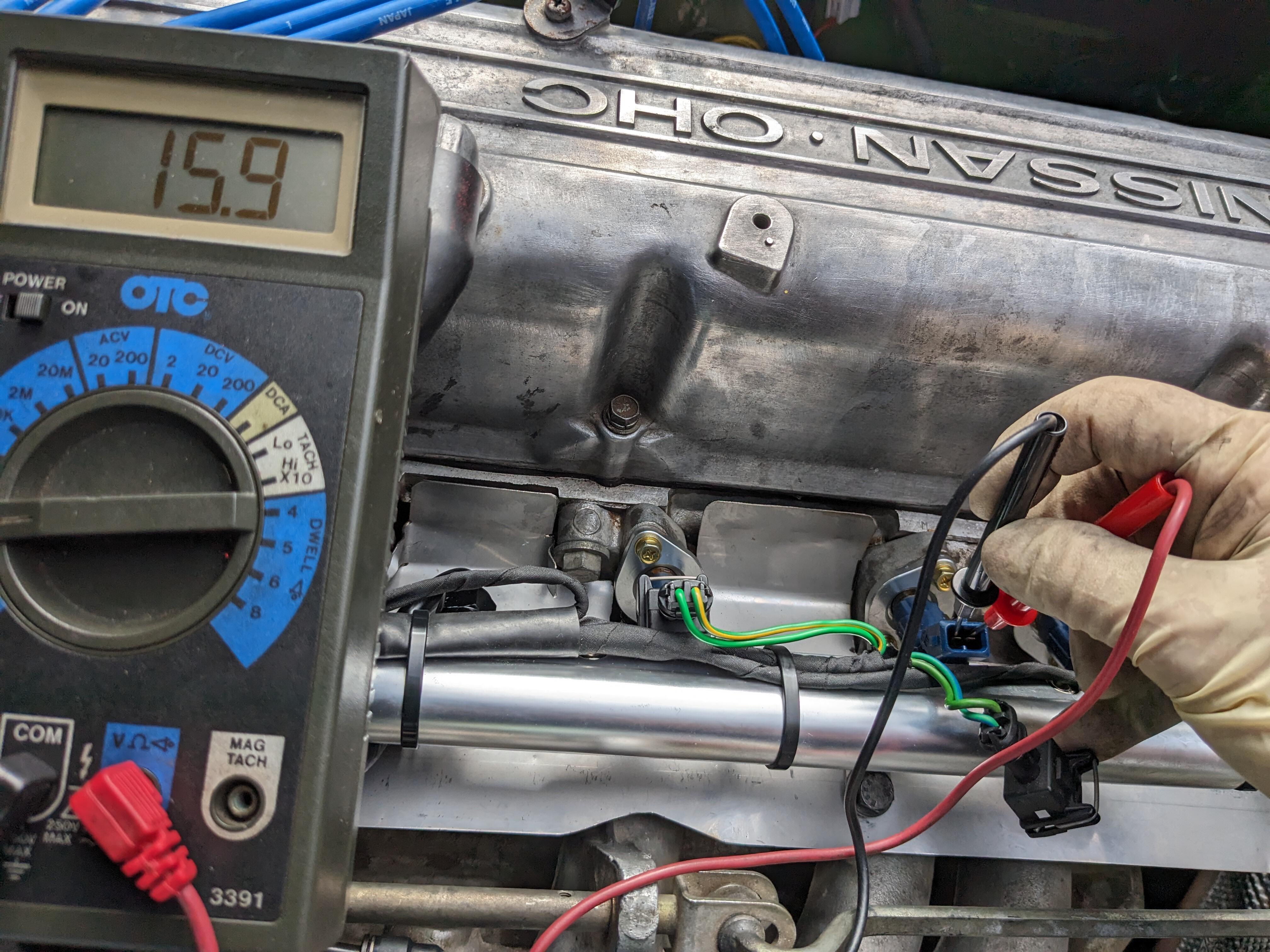
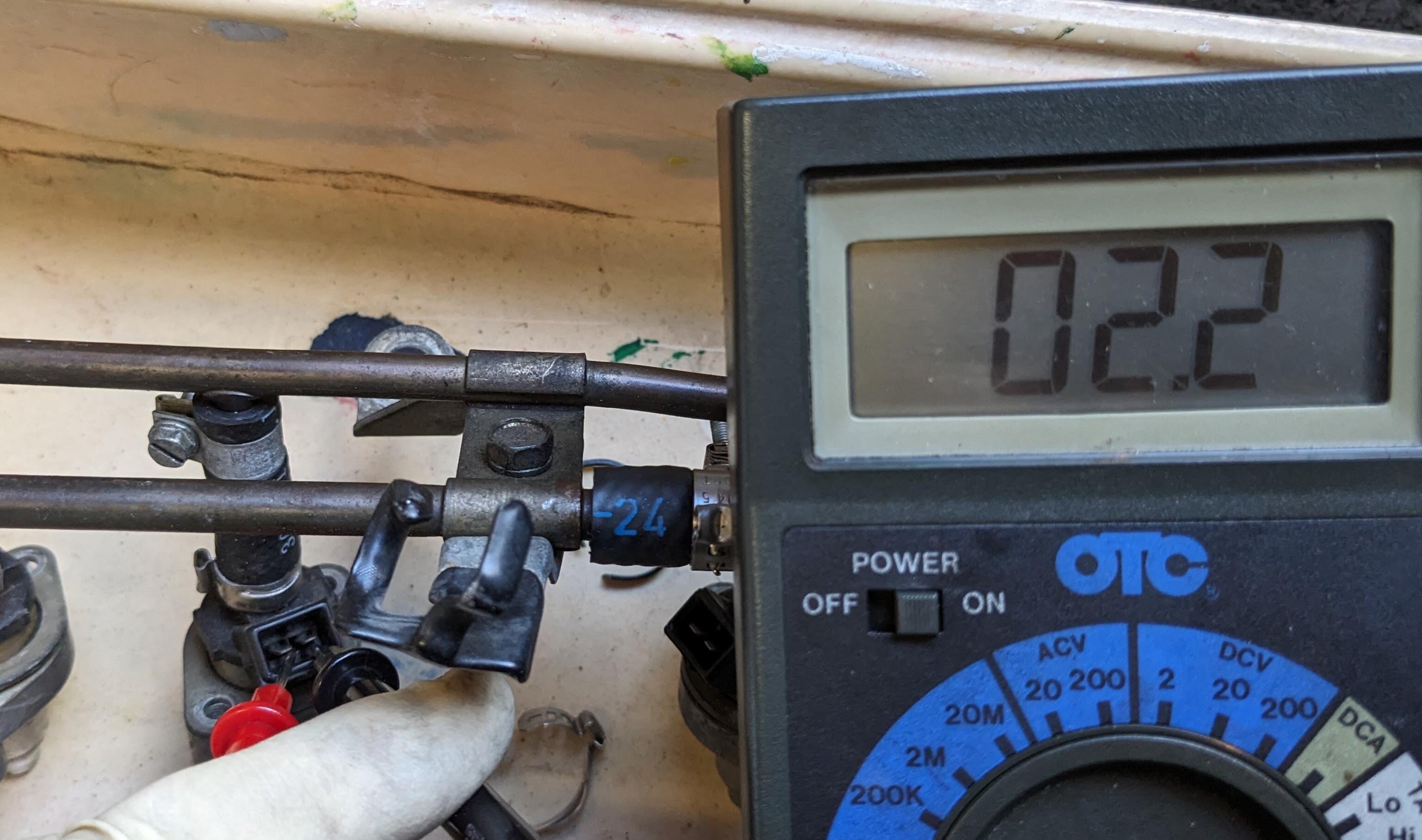
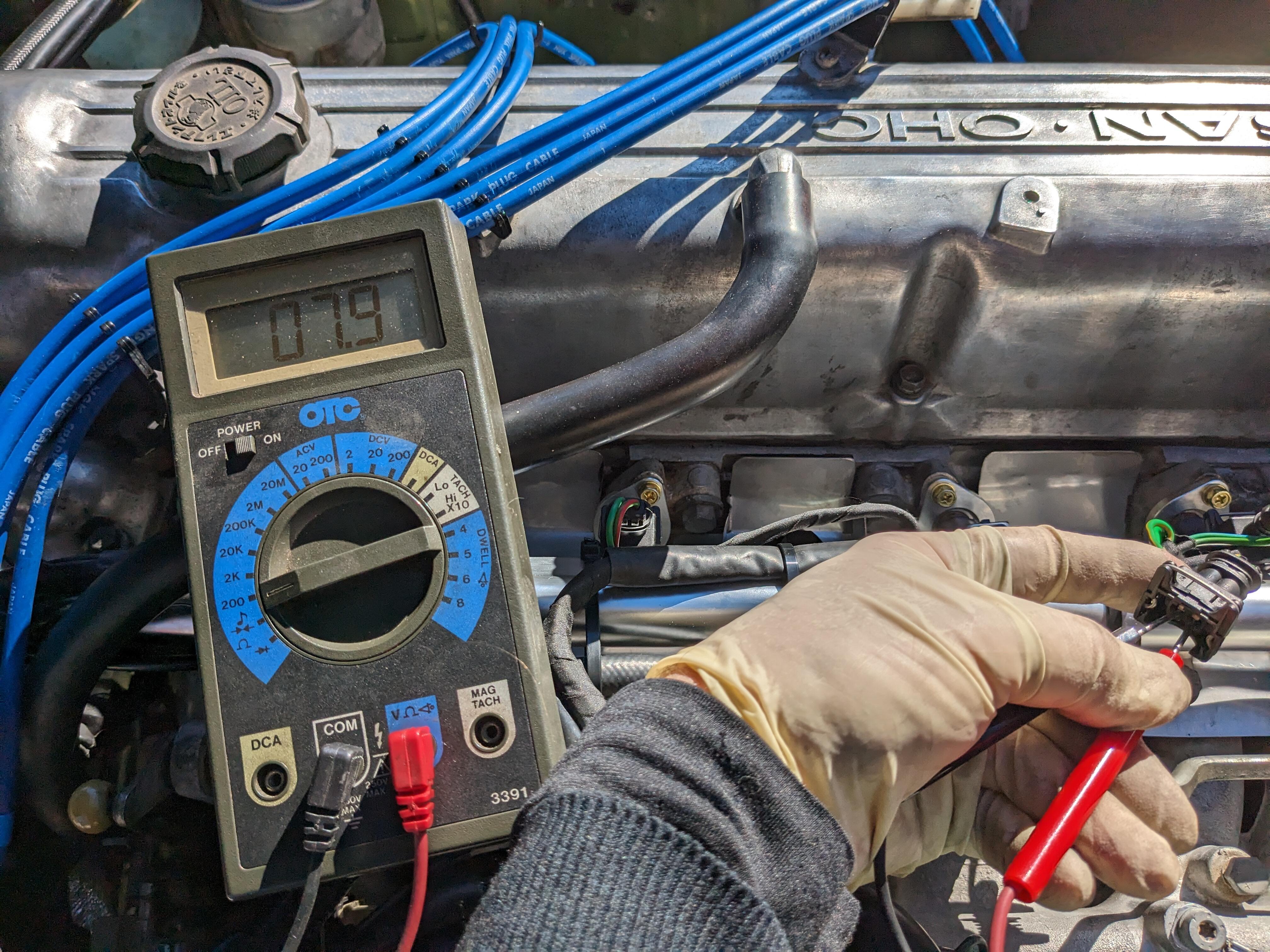
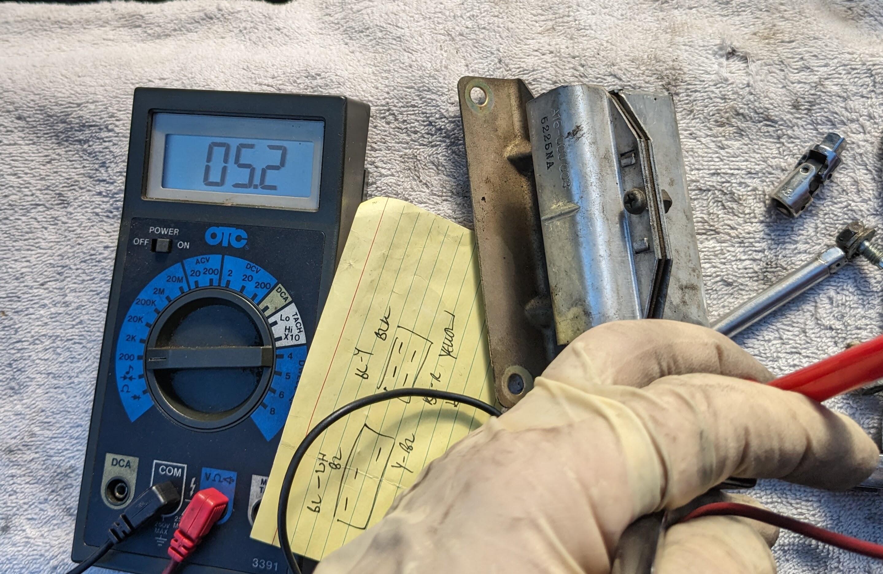
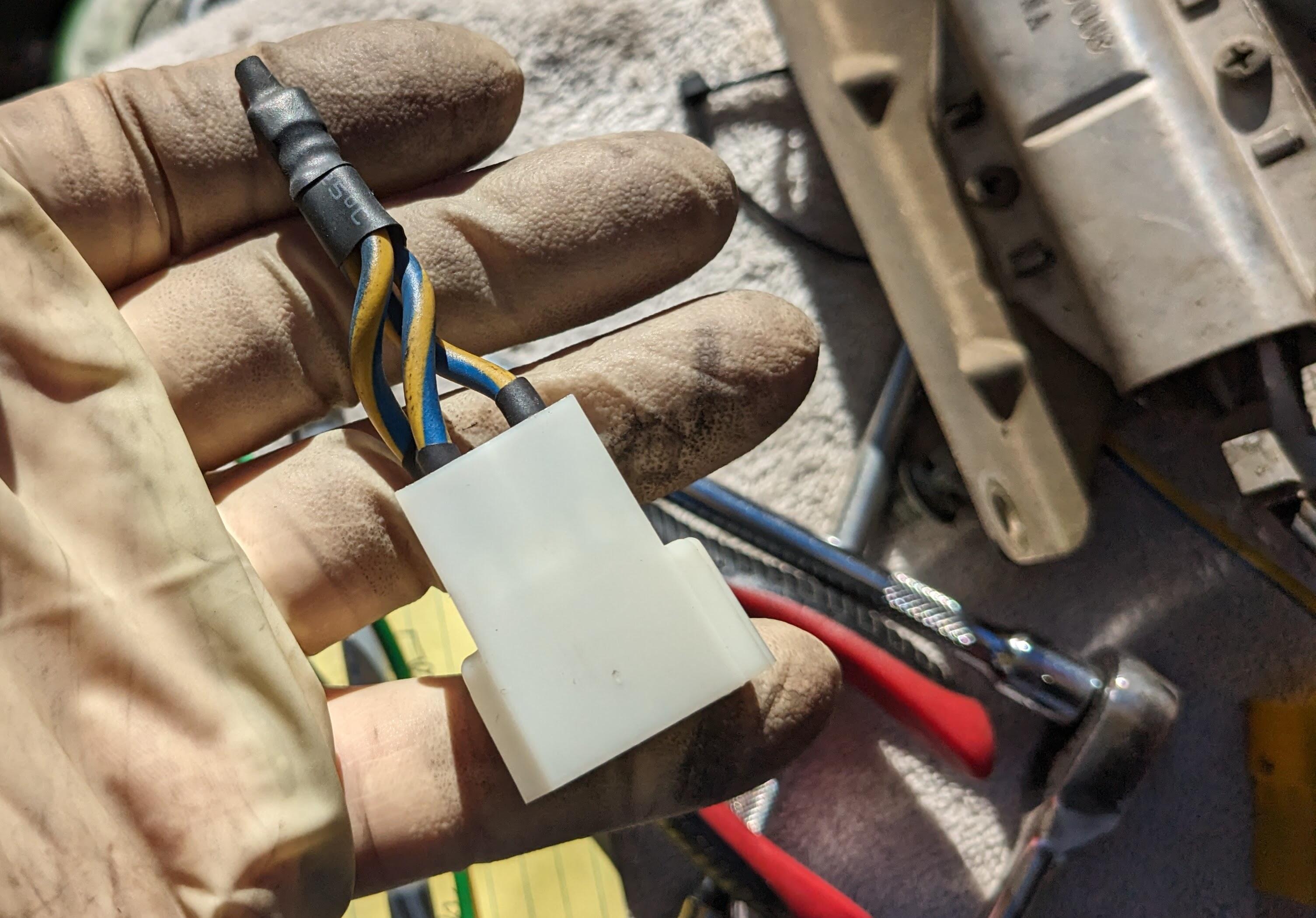
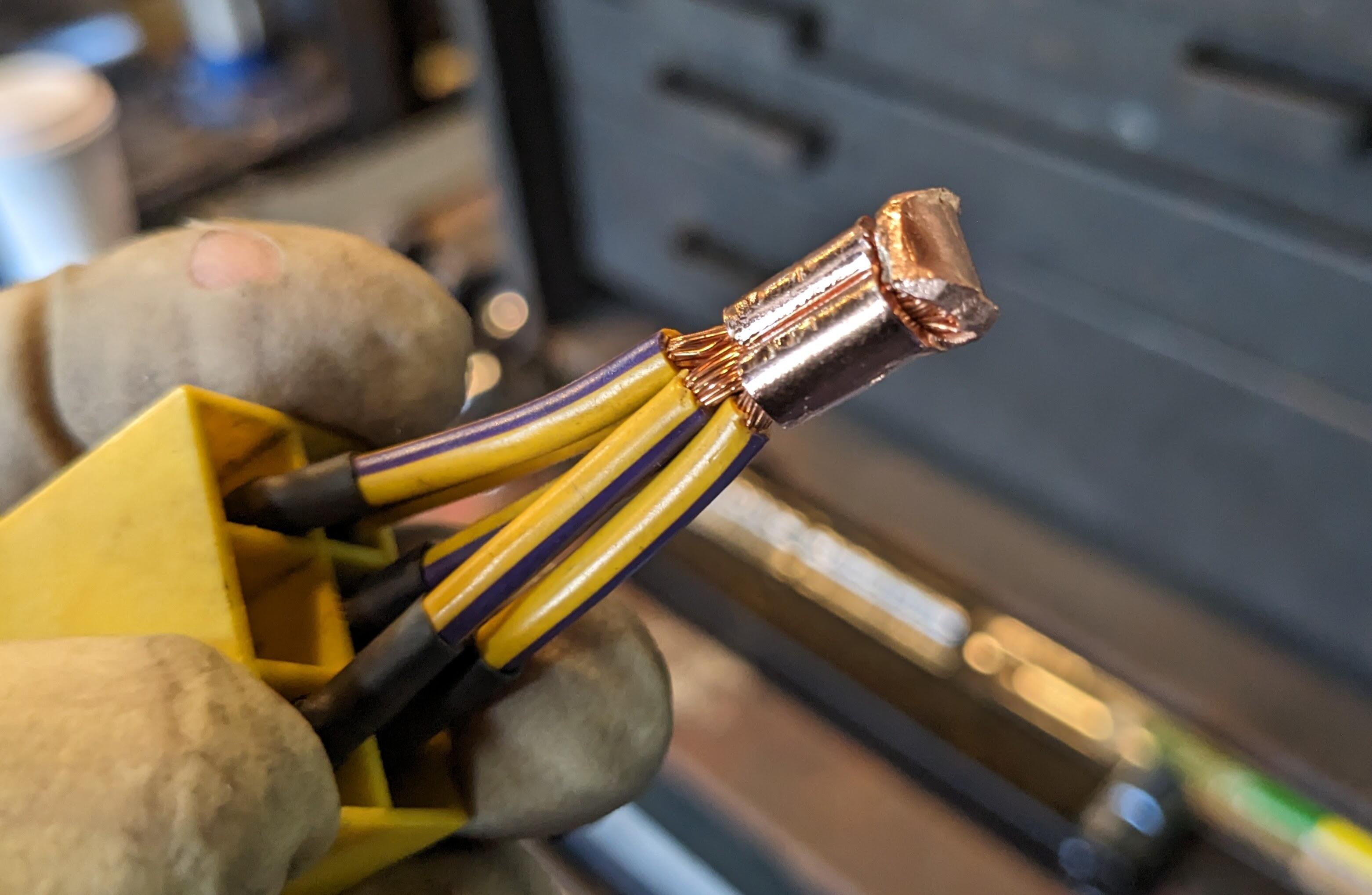
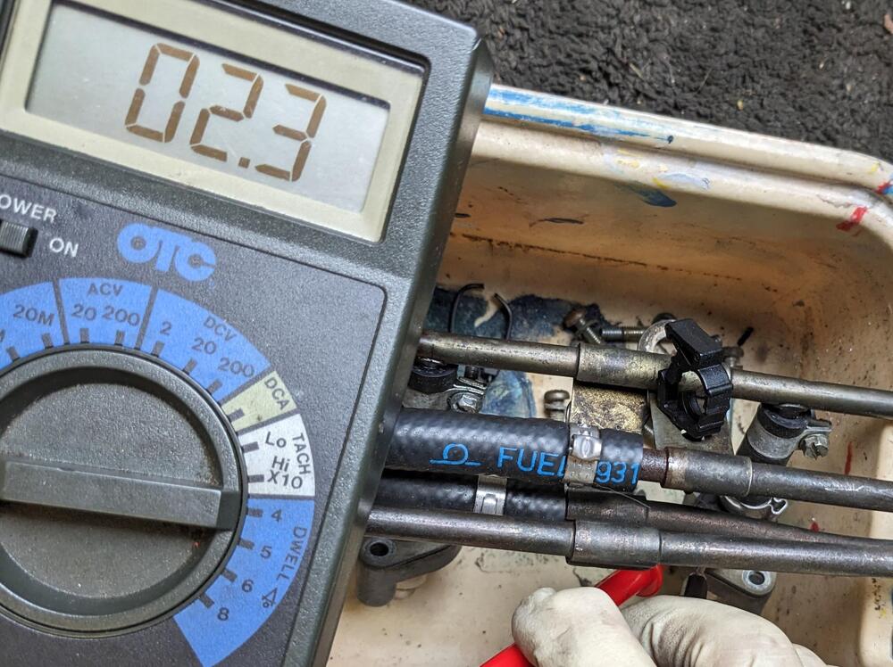
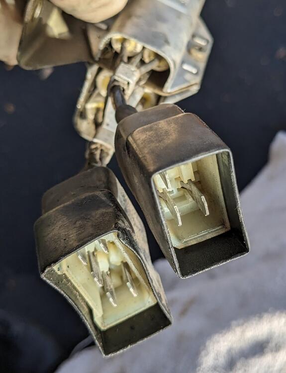
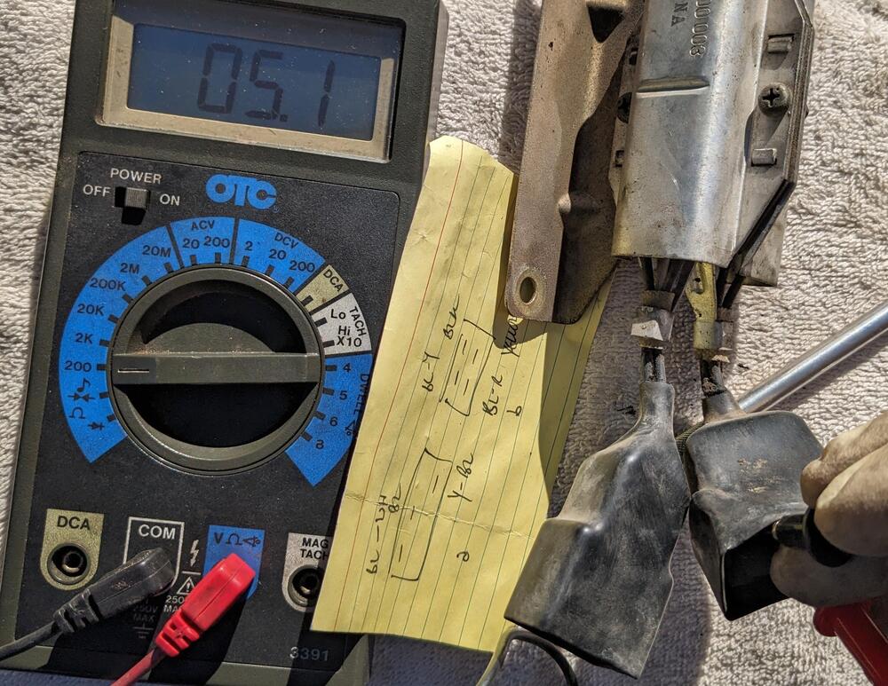
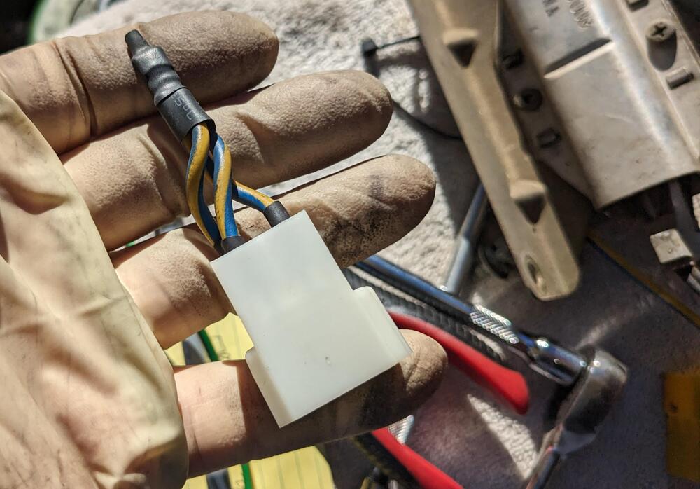
Took a number of resistance measurements today lead resistance .3ohm harness resistance, with ballast 17.1ohm (all the same) Injector resistance - All 15.6ohm stock injectors 1.9-2.0ohm Ballast pack - very clean terminals 4.8-4.9ohm Harness resistance with Ballast pack bypassed 7.6ohm 2 bypass plugs to maintain the integrity of the original harness. 4pole (3 wire) sleeved with heat shrink to approximate stock boot 6pole (5 wire)


-
I asked about the high/low ohm injector combination issue on one of the Volvo forums, as this applies to some early Volvo LH systems. One of the members had this to say: "sorry, you don't want to do that. If you use high impedance injectors with a resistor pack, it roughly doubles the resistance. This means the current flow through an injector is ~1/2, which results in ~1/4 the opening force on the injector pintel. This can cause slow injector opening and/or the injector not fully opening." Another gave more detailed response: "Your injectors are clearly opening; but, the injector offset (which some people refer to as injector opening time) is affected by the injector operating voltage which is now much lower than design. When you reduce the injector voltage the offset increases and the actual injector pulse width is reduced compared to the commanded pulse width. At wide open throttle or close to wide open throttle where the commanded pulse widths are large the error caused by the increased offset may be less significant although the engine will run with a slightly leaner fuel mixture. At idle and low engine load where the injector is operating with small pulse widths it will have a larger % effect on the actual pulse width. At worst, if the reduced pulse width intersects with the injectors non linear region you can cause extremely unstable idle. At best, the reduced pulse width will result in a leaner than ideal fuel mixture at idle and low engine loads." and "I assume that 205CC means 205 ml/min flow rate for the injectors. If so, that is not a particularly large injector which means that your idle pulse widths are fairly large and probably well out of the non linear region which means the increase in injector offset may have a less significant effect. So, the car may still operate right now; however, if you ever have to do a cold start on a cold day with a compromised battery you may run into a no start condition. The reduced battery voltage may result in a complete injector non opening condition at worst or really difficult starting" finally "The good news is that this should be easy to correct. This may be as simple as just deleting / by-passing the original injector resistors. What you need to do is measure the resistance of the original injector and the injector resistor. Add the values together. The 0280 155 712 injector appears to be really high resistance - 16 ohms. As long as the added value of the original injector and injector resistor is less than the resistance of the new 0280 155 712 injector it is 'safe' to just delete / by-pass the injector resistor. I suspect that this will be the case because most low impedance injectors were around 2-3 ohms with external injector resistors in the 5 - 10 ohm range so a total resistance in the 7 - 13 ohm range." I'm going to go ahead and bypass the resistor pack, after I measure the values.