HusseinHolland
Free Member
-
Joined
-
Last visited
Everything posted by HusseinHolland
-
 OK - I 'll mark it up carefully & see how it goes.
 -
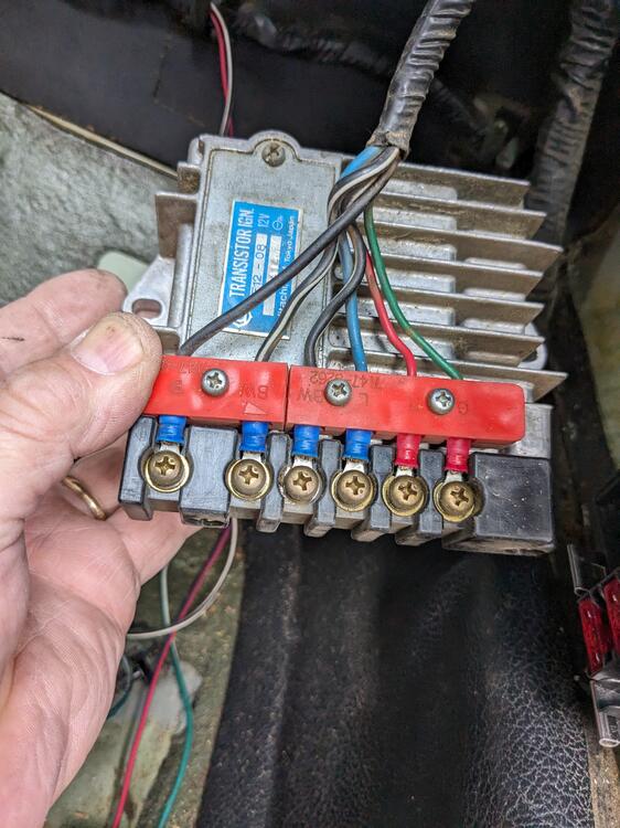
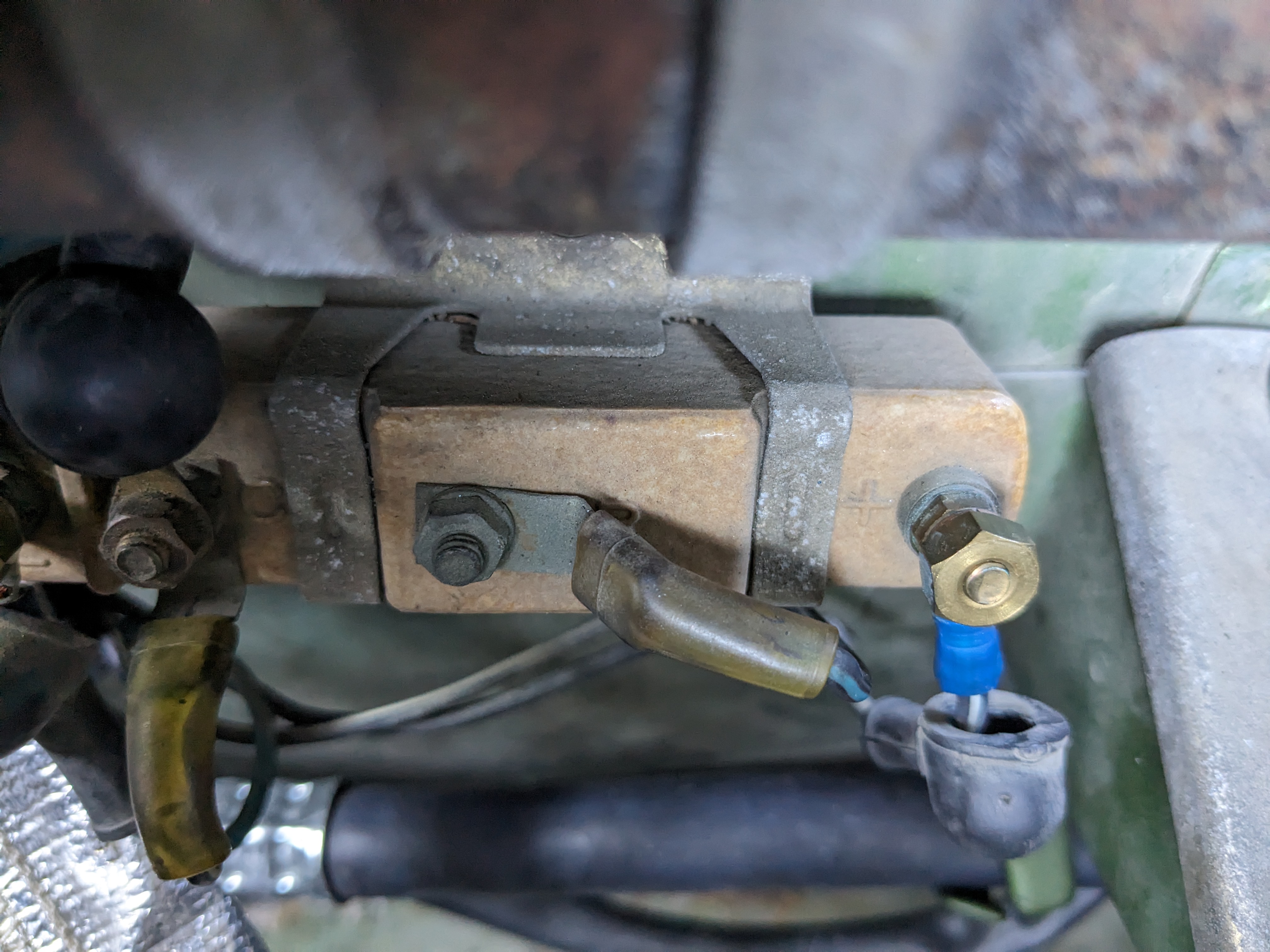
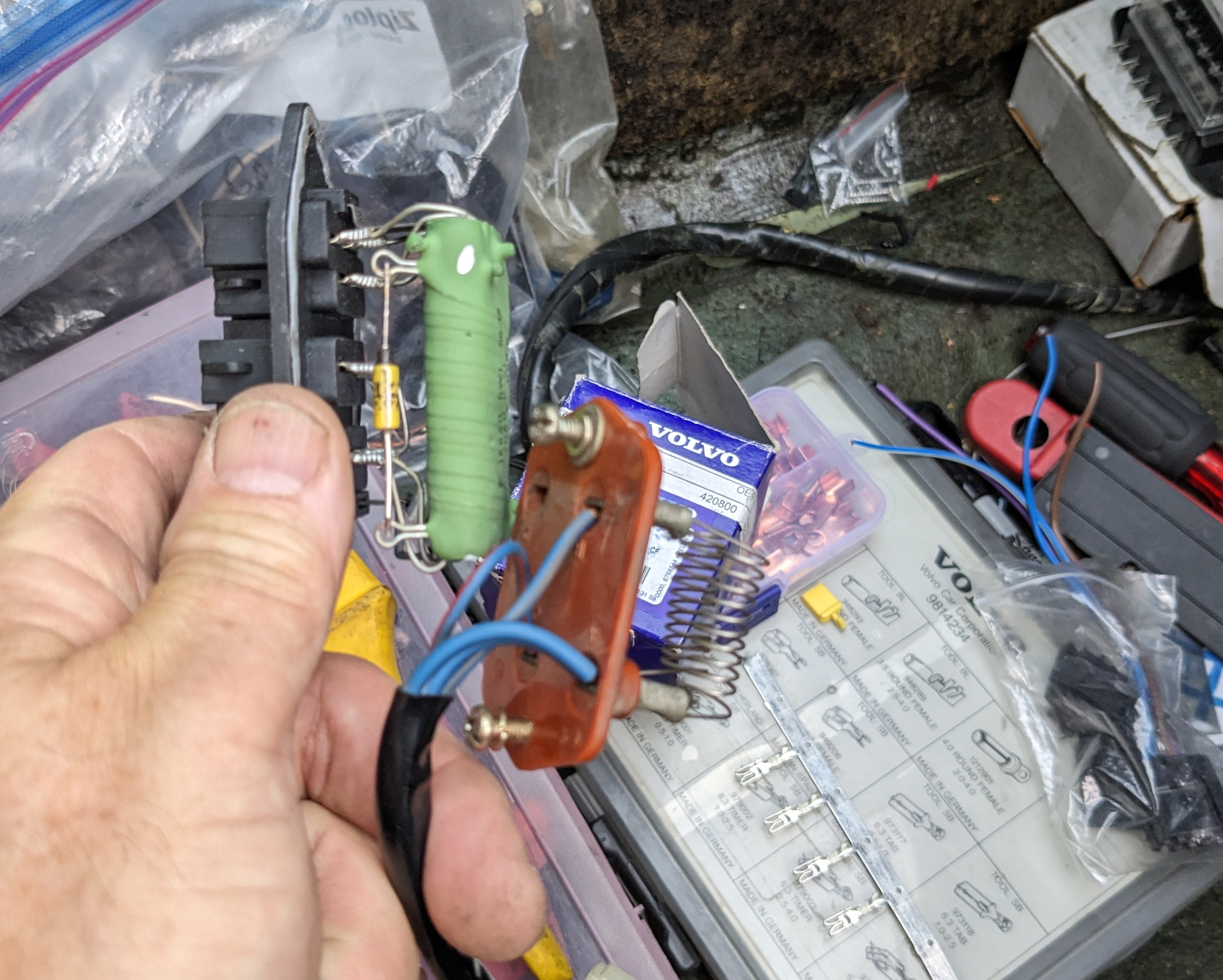
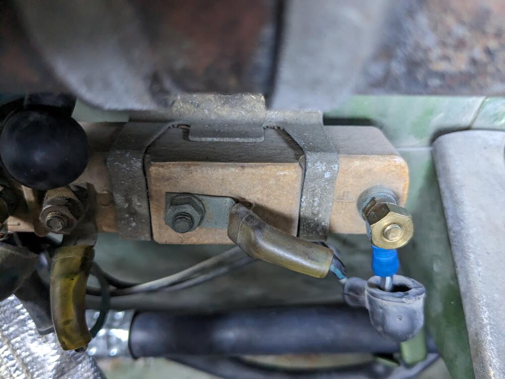
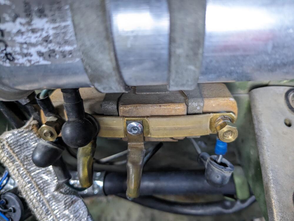
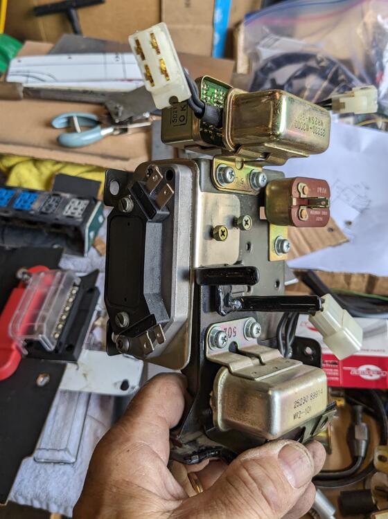
Did the resistor bridge today, and installed the Bosch coil original center post snapped off, so I riveted the spade tang to the bridge. Doesn't really matter since the coils gets full battery voltage at any of the connections
-
I see - my 75 didn't have any under dash panels, period. I was interpreting the schematic as illustrating complex bracketry for the floor panels - that would have sucked 😄
-
Thank you, Steve. Certainly better than nothing, just not clear Eurodats' pic from his 280Z
-
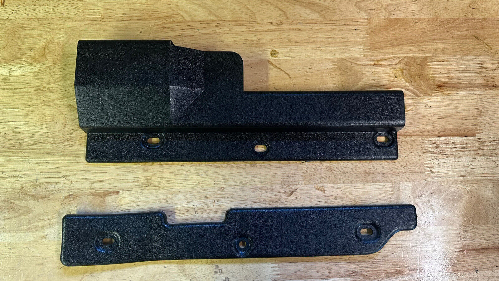
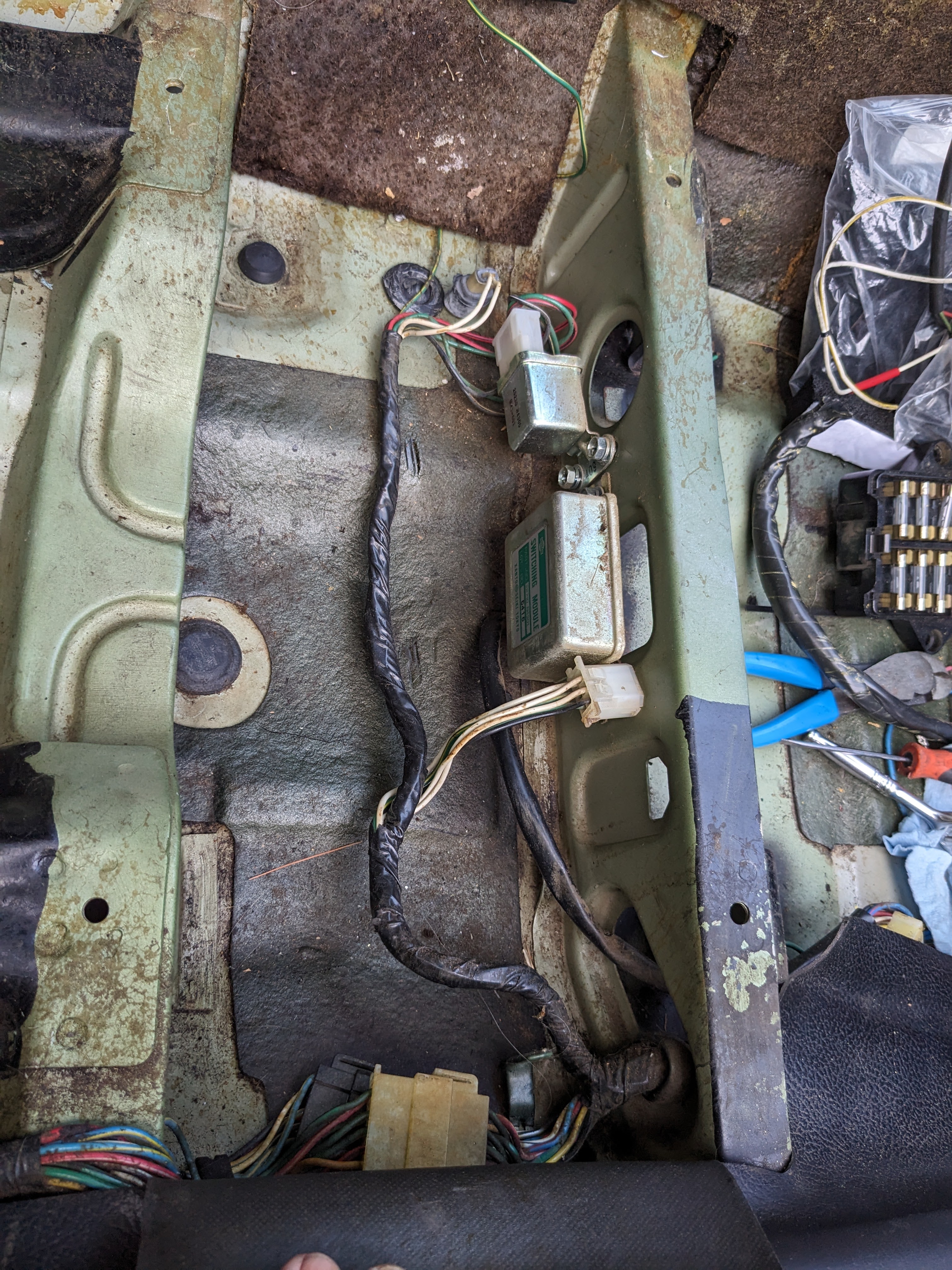
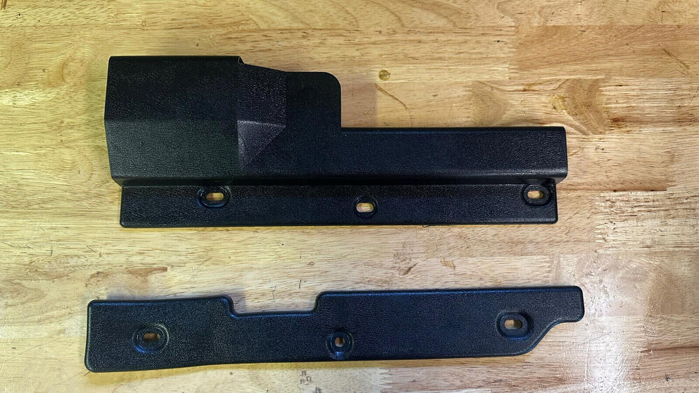
I've seen pics of interiors that have the trim panels under the pedals & covering the wiring on the right (for example in EuroDat's HEI conversion thread, pic showing his ICM wiring). I'm going to add them to my 75, I just can't find any pics that show the mounting point itself. Are they secured directly to the floor/bulkhead, are there raised mount tabs? If anyone has pics with the carpet out where the mounts are visible, that would be awesome. There are 3 mount points per side.
-
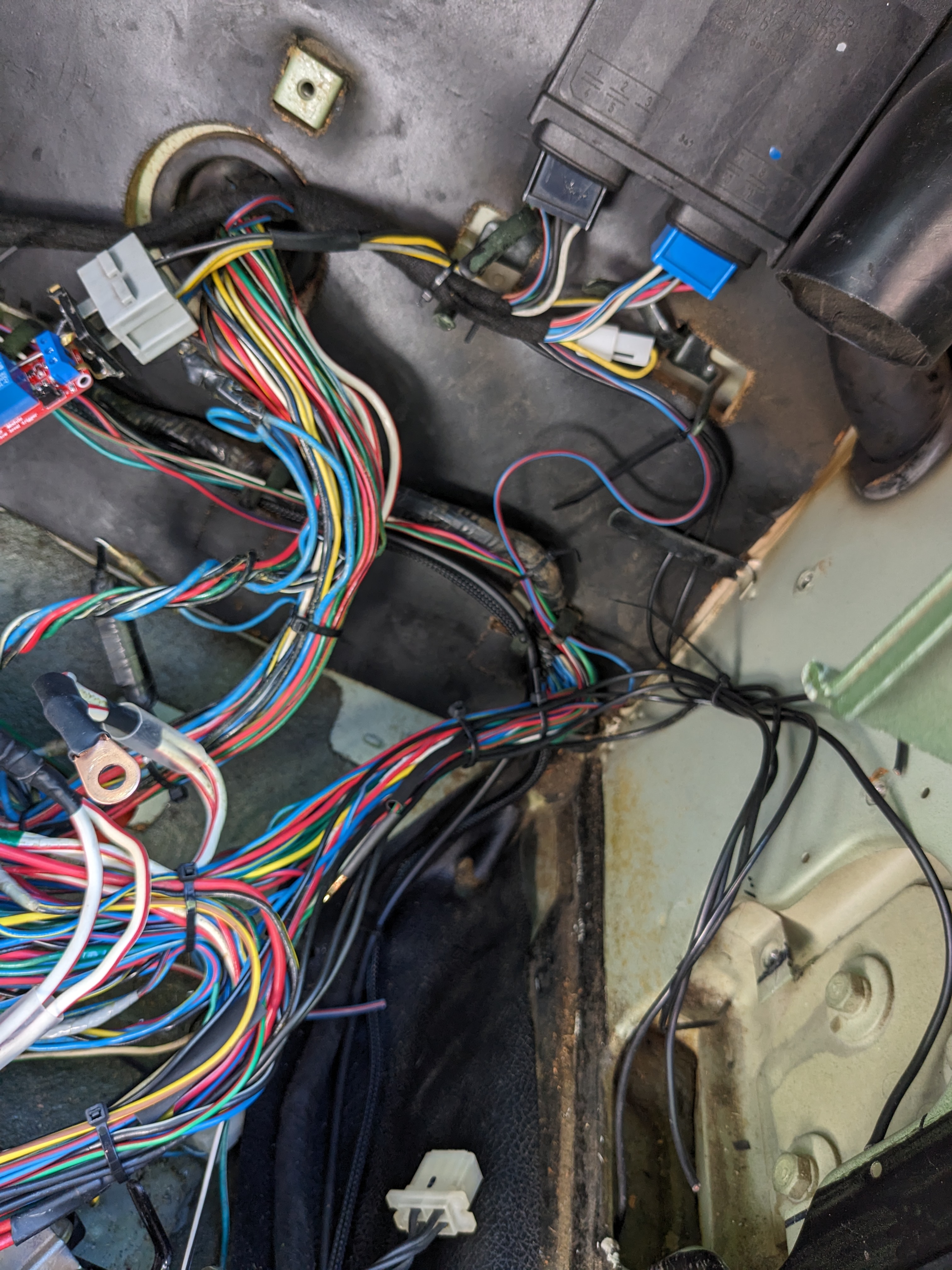
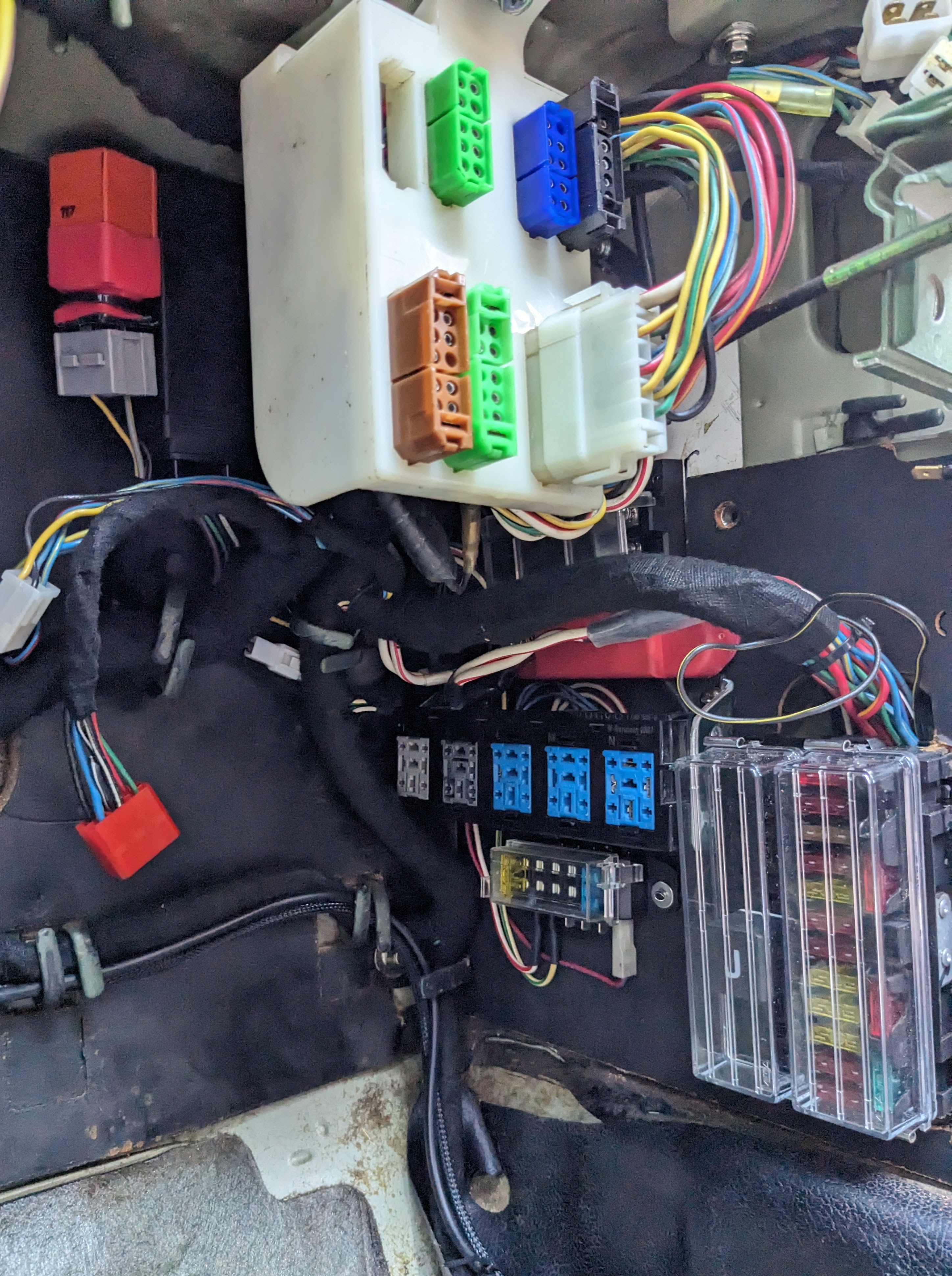
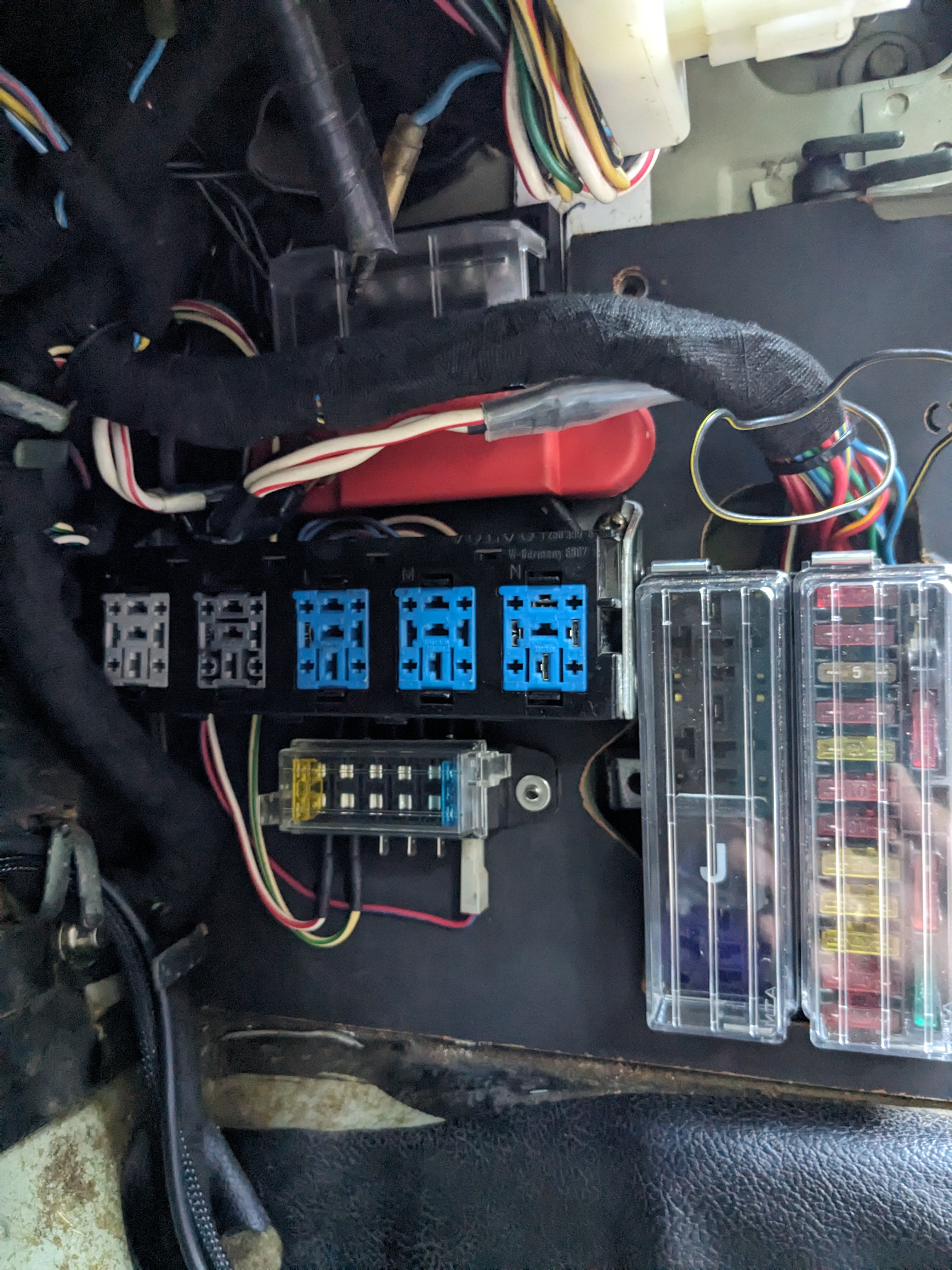
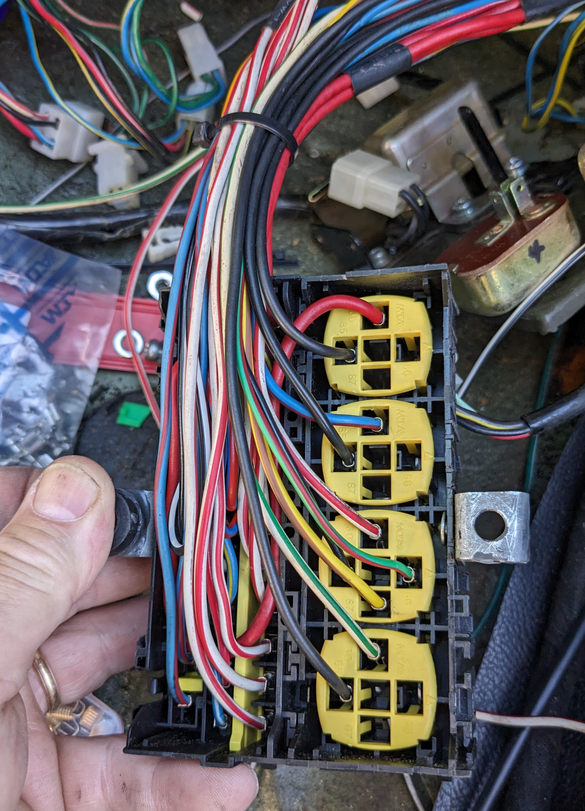
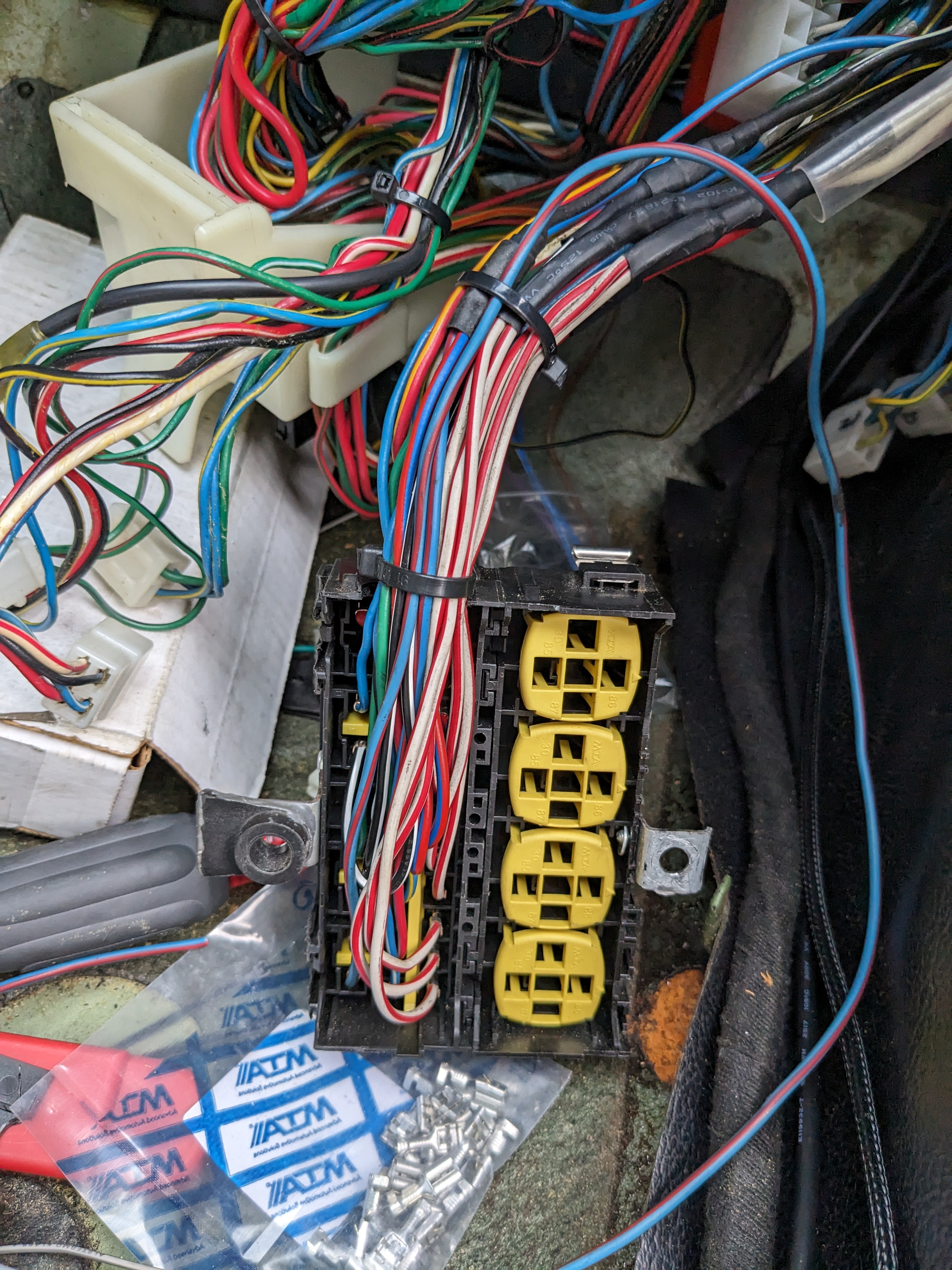
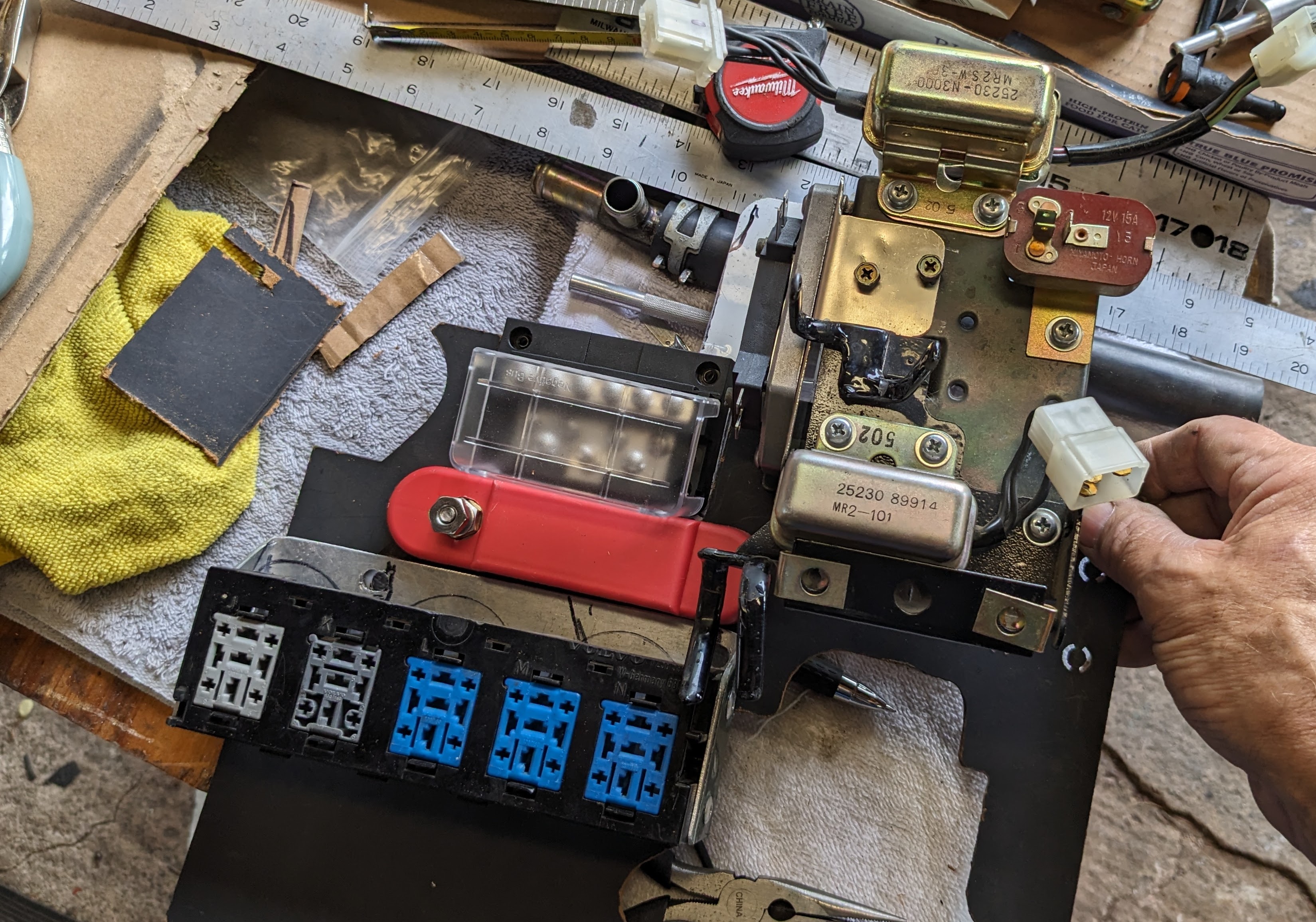
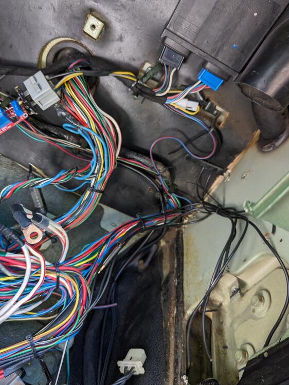
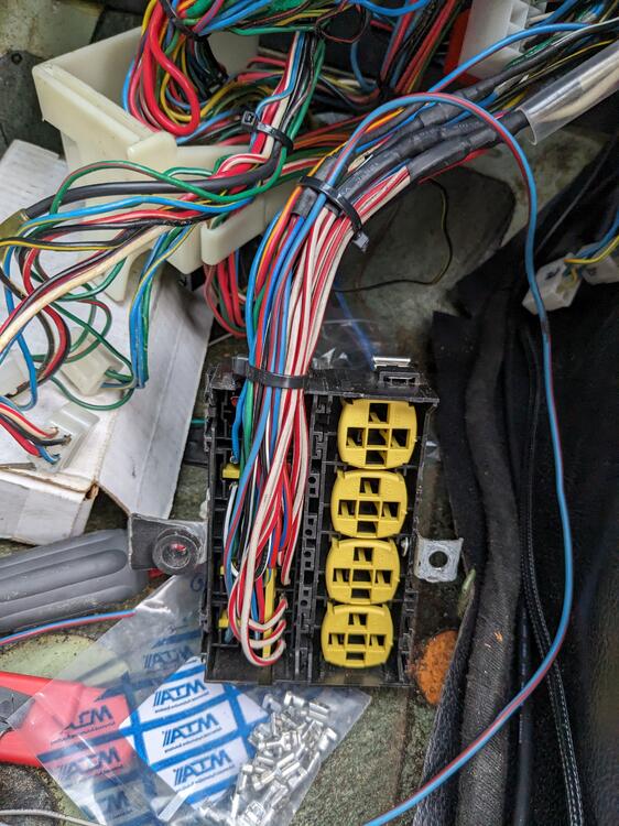
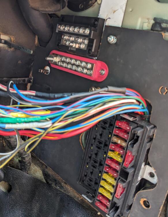
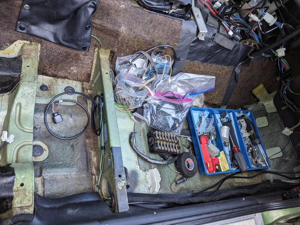
Worked on the power circuits today Organizing additional wiring, relay grounds Wired spare relay sockets with power & ground. Only 2nd from bottom is needed right now (AC-on blower fan override) Wiring secondary relay panel, additional 6 fuse panel, ground, 30 & 15 rails 15 rail is part of relay panel. Volvo inserted 3 rails in the relay/fuse panels. I kept this one. making sure that everything can be removed, and has enough cable slack to move out of the way as needed test fit again, re-wrapped harnesses, place CIS module


-
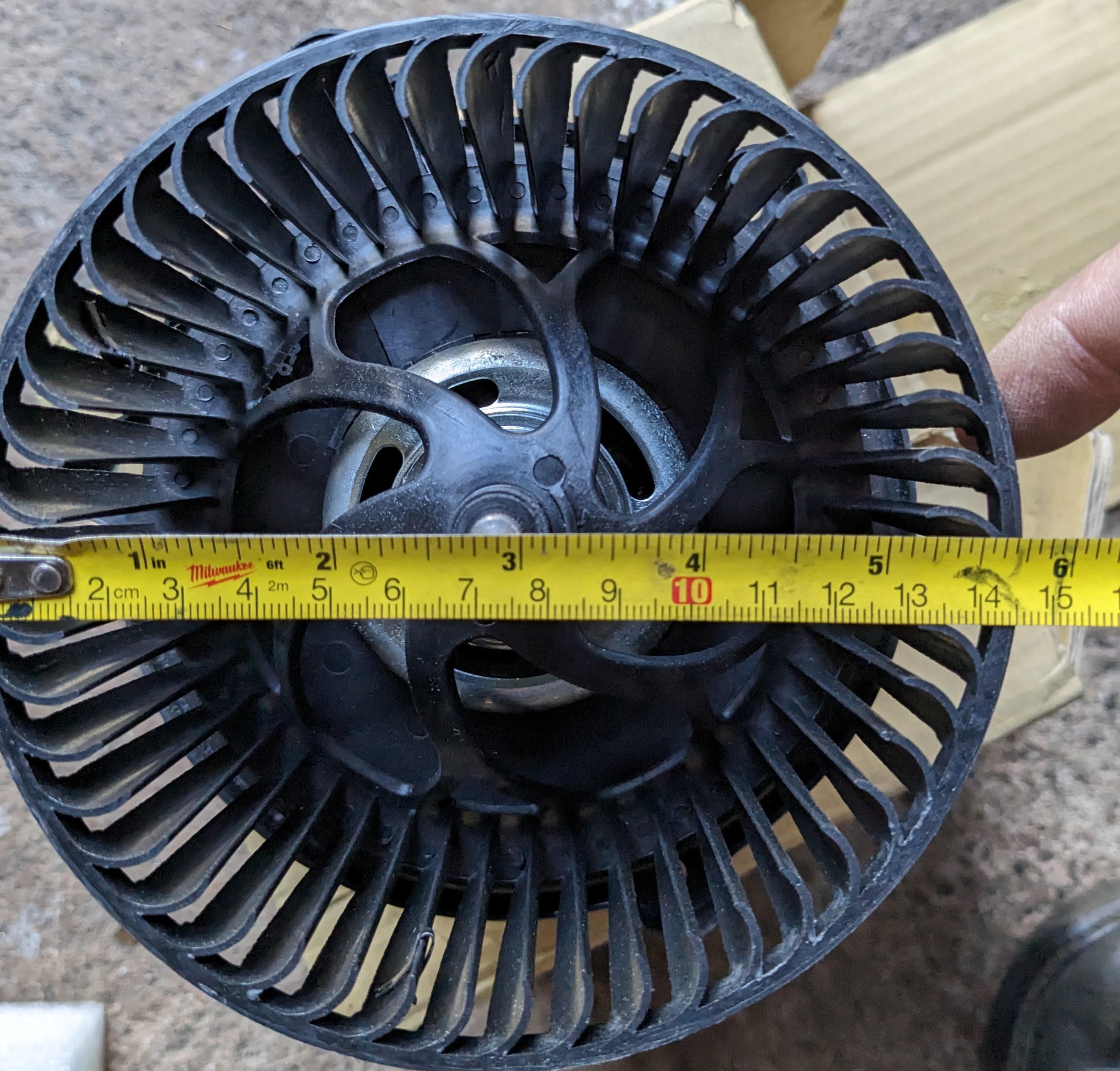
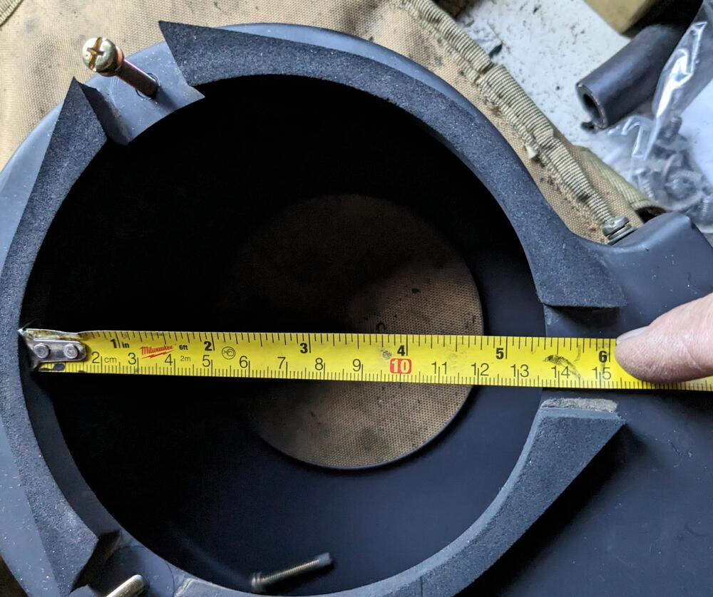
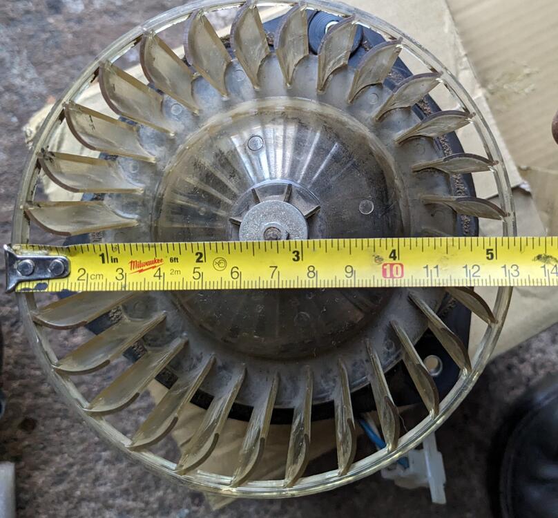
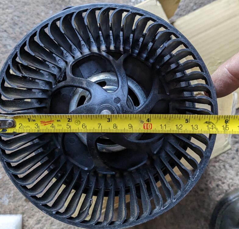
Pics of my box opening, stock motor cage & Kia (4Seasons) cage. Cages are not interchangeable, shaft design varies 5 3/8" opening Stock cage just under 5 1/4" Kia Cage 5 3/4" (!) 1/2" is too much meat to remove - the wall is pretty shallow in the 2 o'clock area above
-
The cages are not the same form factor. I'll take some pics of what I have. Perhaps different brands vary, the 4 seasons motor is much lighter weight, smaller motor than my 75 Z version, cage is larger.
-
I'll take some pics with measurements - my recollection when I tried to place it was that the discrepancy was much more than 1/16" with the 4Seasons motor Yeah, If the shaft fitment is the same, that will be preferable. My 280Z has deep foam & metal spacers for the factory blower to get the correct offset. I'm wondering if it's even worth the bother. The Z motor has much more heft to it. I'm dubious as to the newer motor having more 'zest' than the original.
-
Yes - the OD of the squirrel cage, that impedes the install in the stock opening.
-
Still haven't installed the Kia motor yet - the one I bought seems like it's more than 1/16 to an 1/8" larger OD - I'll have to take some compassion pics - I don't see any actual install mod pics in this or the original linked thread.
-
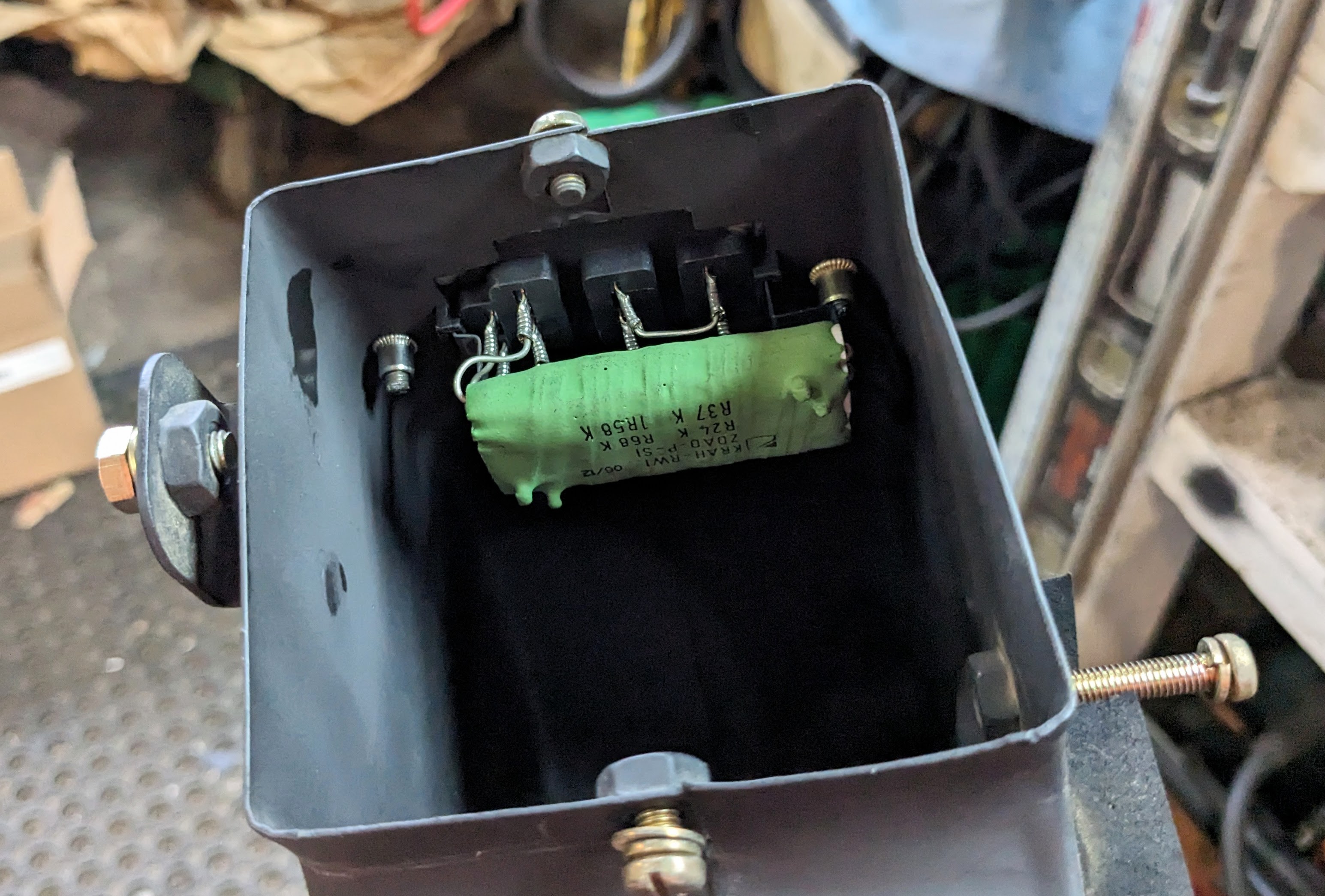
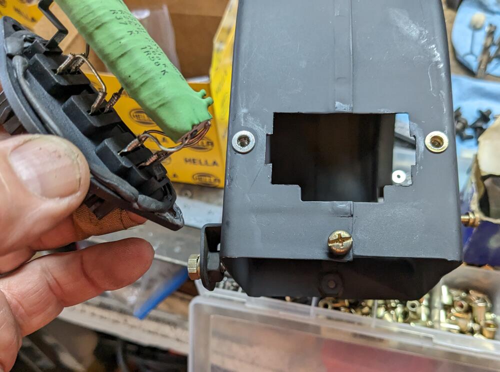
Another rain-drenched day 😞 On a plus note, I have both factory under dash vents & the r/s elbow on order 🙂 I couldn't work outside, so I fitted the Volvo fan speed resistor to the blower casing. M4 rivnuts to retain it, added a little extra butyl to adjust for the folded seam Nissan used here

-
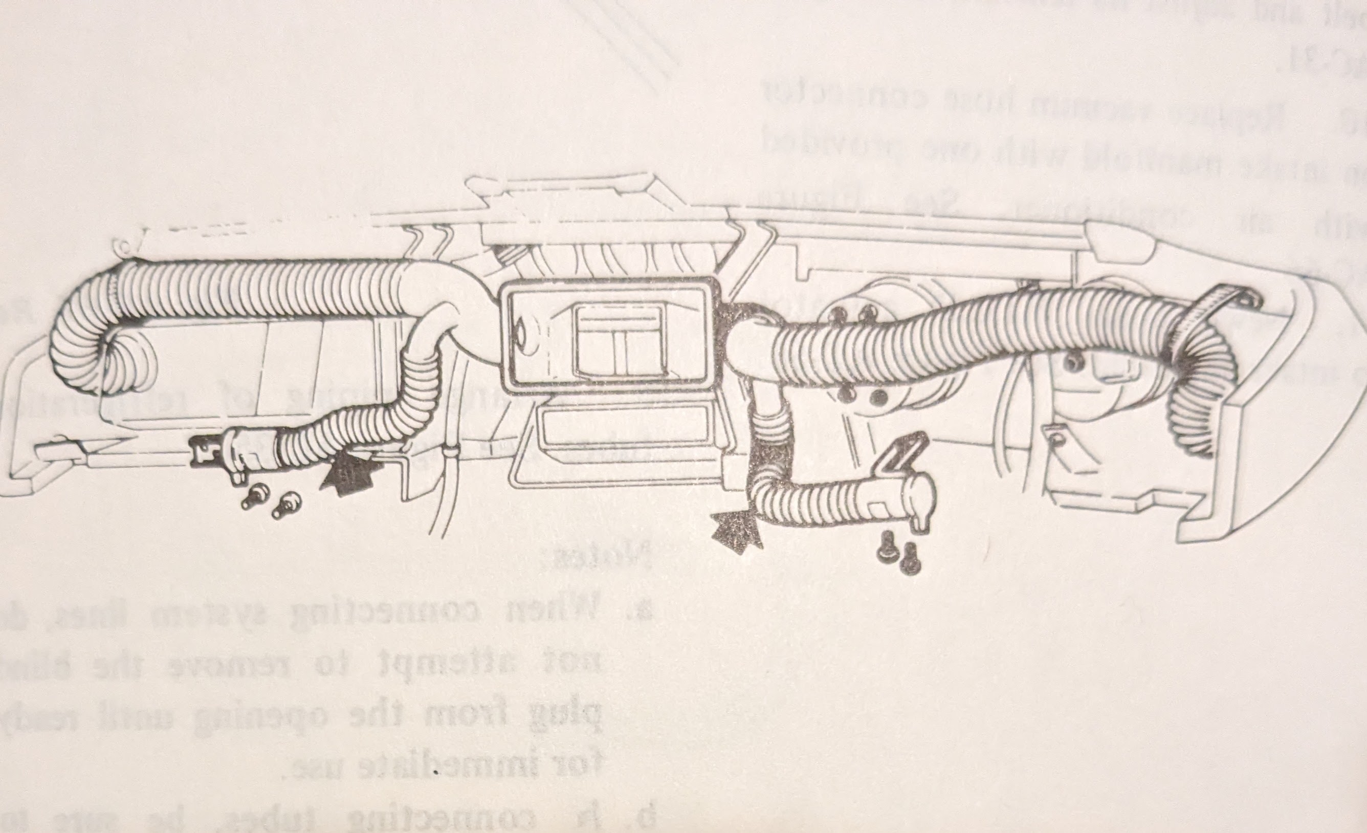
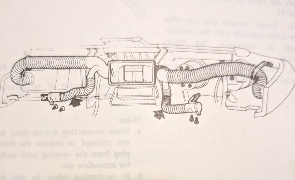
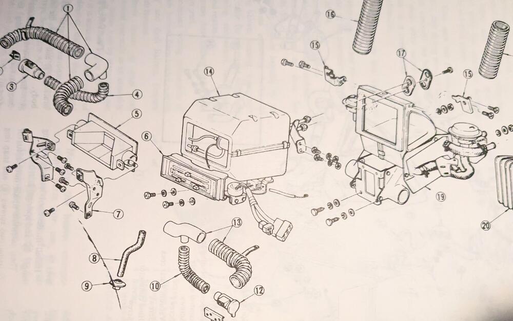
Looking in the FSM at the AC related ducting and schematics, I see that factory AC came with blower ducts that sit under the dash(?) EDIT - found the left vent , working on the right vent + right elbow E Wondering if anyone has added universal vents that approximate the factory supplied version. My Aftermarket setup had none, only center & dash end vents connected items, 3, 12 & 13 are what I'm missing - I do have the "Y" elbow on the driver's side, just was blocked off. I have looked at vintage air, etc., however those vents all seem to be oversize for what I need
-
Sorry - missed this - waiting for the meter so I can try to deal with caps at the same time if needed.
-
I didn't bother mentioning as I opted for a repackaged OTC 3940 multimeter that was discounted pricing. Typically (in my experience) Amazon listings sold this way are just open box, not actually used items. In this case it was completely dead.
-
I ordered one of the Cap-only test meters off Amazon, the multimeter I ordered was DOA. So, back to this once that arrives
-
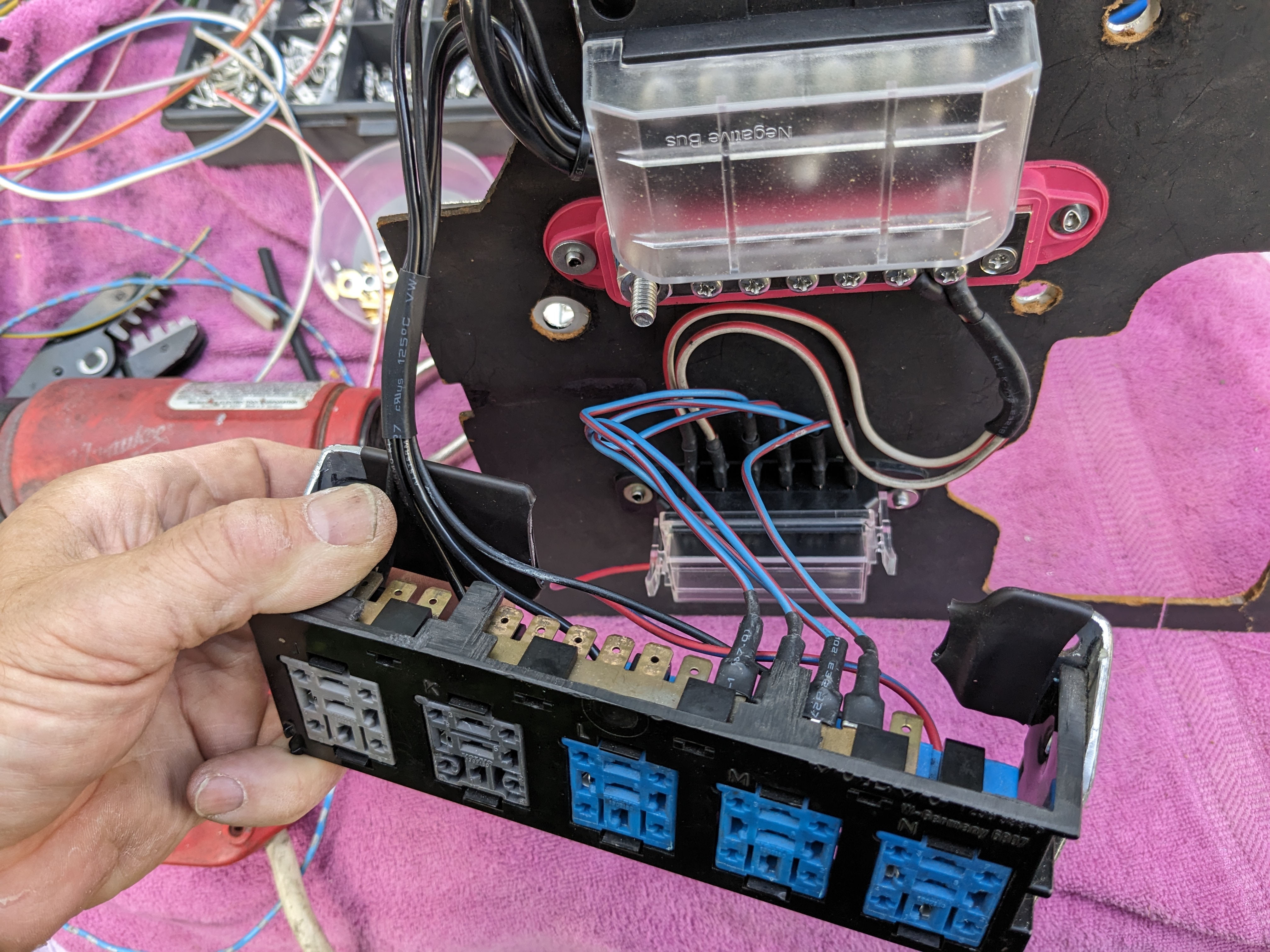
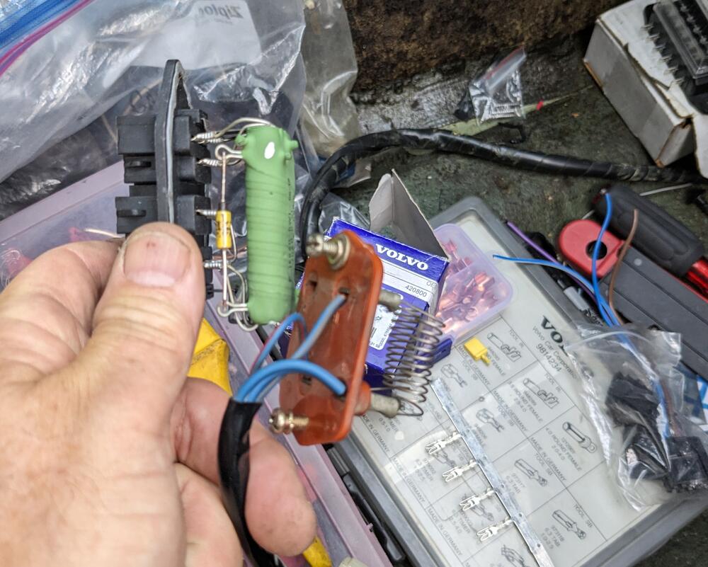
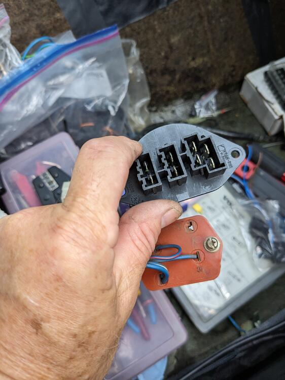
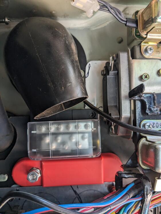
Adding switched power to one relay to be used to switch the blower fan on low (1) speed when AC is engaged Spliced the main battery feeds to run to the ancillary power strip before going to the new fusebox Going to use a Volvo fan speed resistor in place of the 3 speed non AC setup I have. I'll modify the blower casing to fit it. Opening only has to be altered slightly. Difference is this mounts from the outside, vs the stock resistor being bolted on the inside. Top 4 pins are speeds 1-4 next 2 pins are full speed, bottom 2 are output to blower motor
-
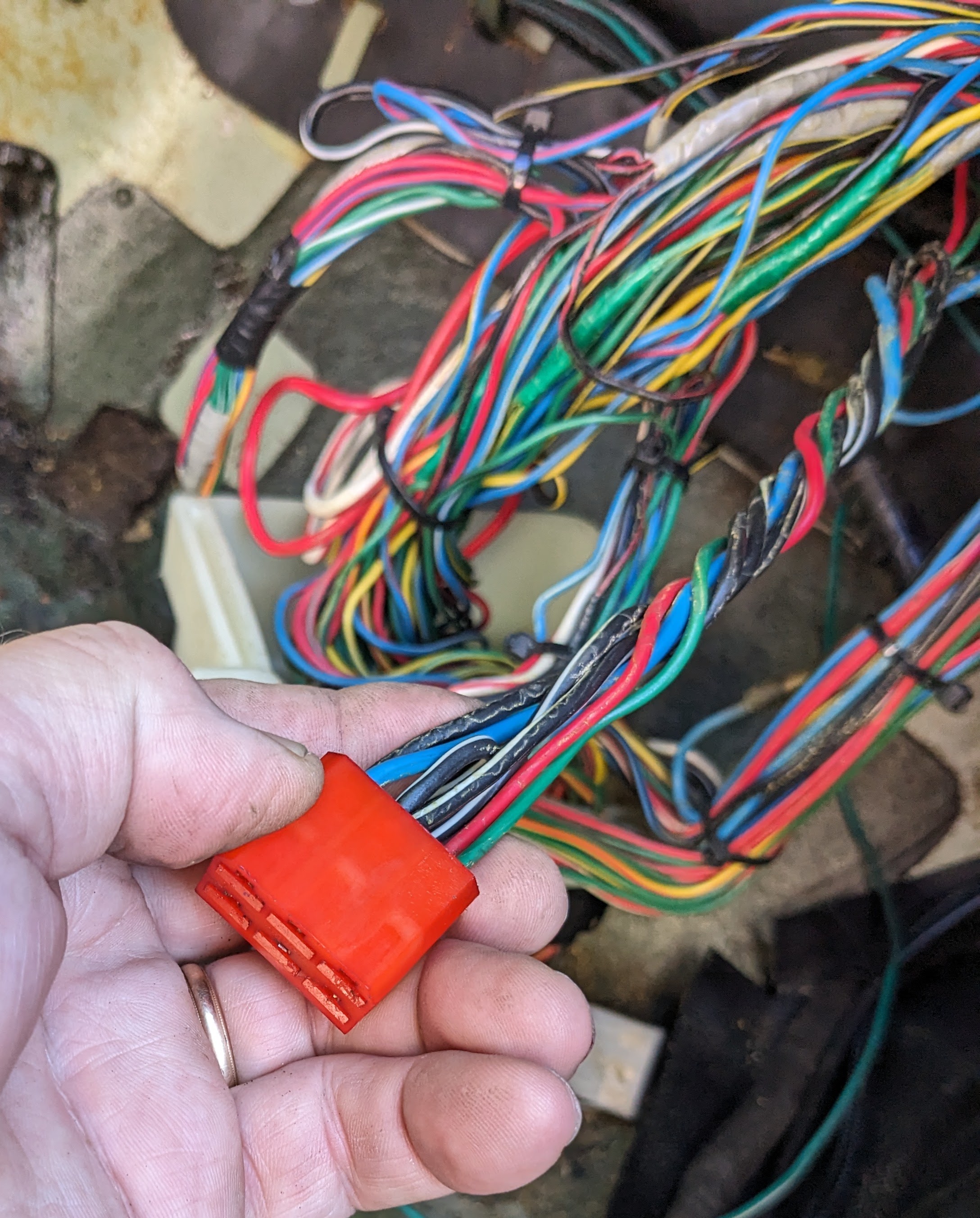
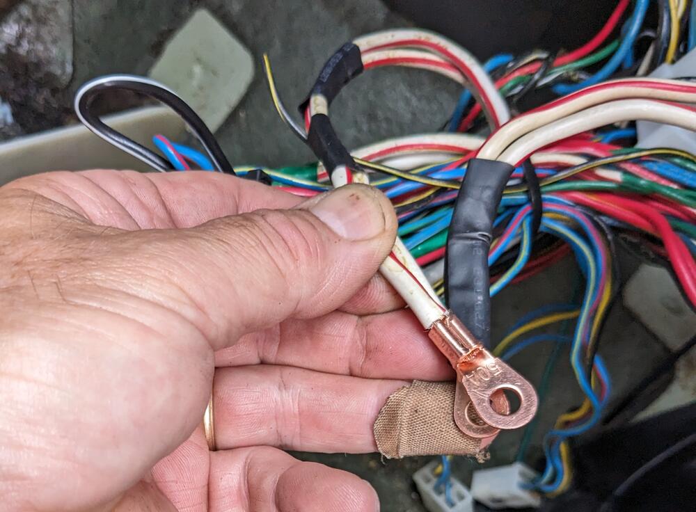
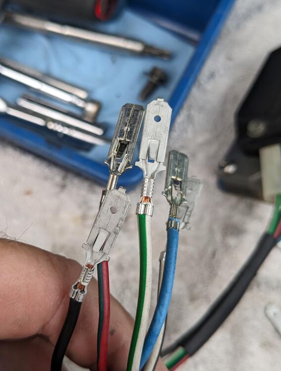
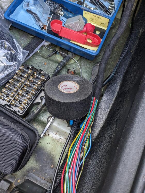
Hopefully I have no actual issues with the module in operation, this is all just about ensuring the wiring is accurate. I wired the sub harness for the HEI module today 6.3mm spades for the connection to the factory harness I made a bridge on the harness side, to connect both Blk-Wh together


-
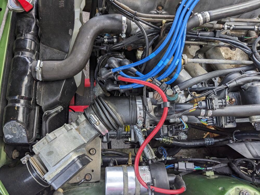
Thanks for the confirmation, EuroDat. I thought about moving it the bay, much less wiring to worry about. Playing with placing the HEI & heat sink, I couldn't find a nice flat spot to locate it, except under the triangle steel web in the left corner near the AFM. Even though I don't plan on driving the car in the wet, the fact that the connections at the HEI are unsealed is enough for me to stick with placing it in the cabin 😁
-
Thanks for your experience, Paul. I had noted in EuroDat's directions that he bypassed the ballast. Since I'm using a Volvo 12v coil that didn't use the ballast to begin with, I am going to do as he did & bridge the ballast terminals, to keep the connections tidy.
-
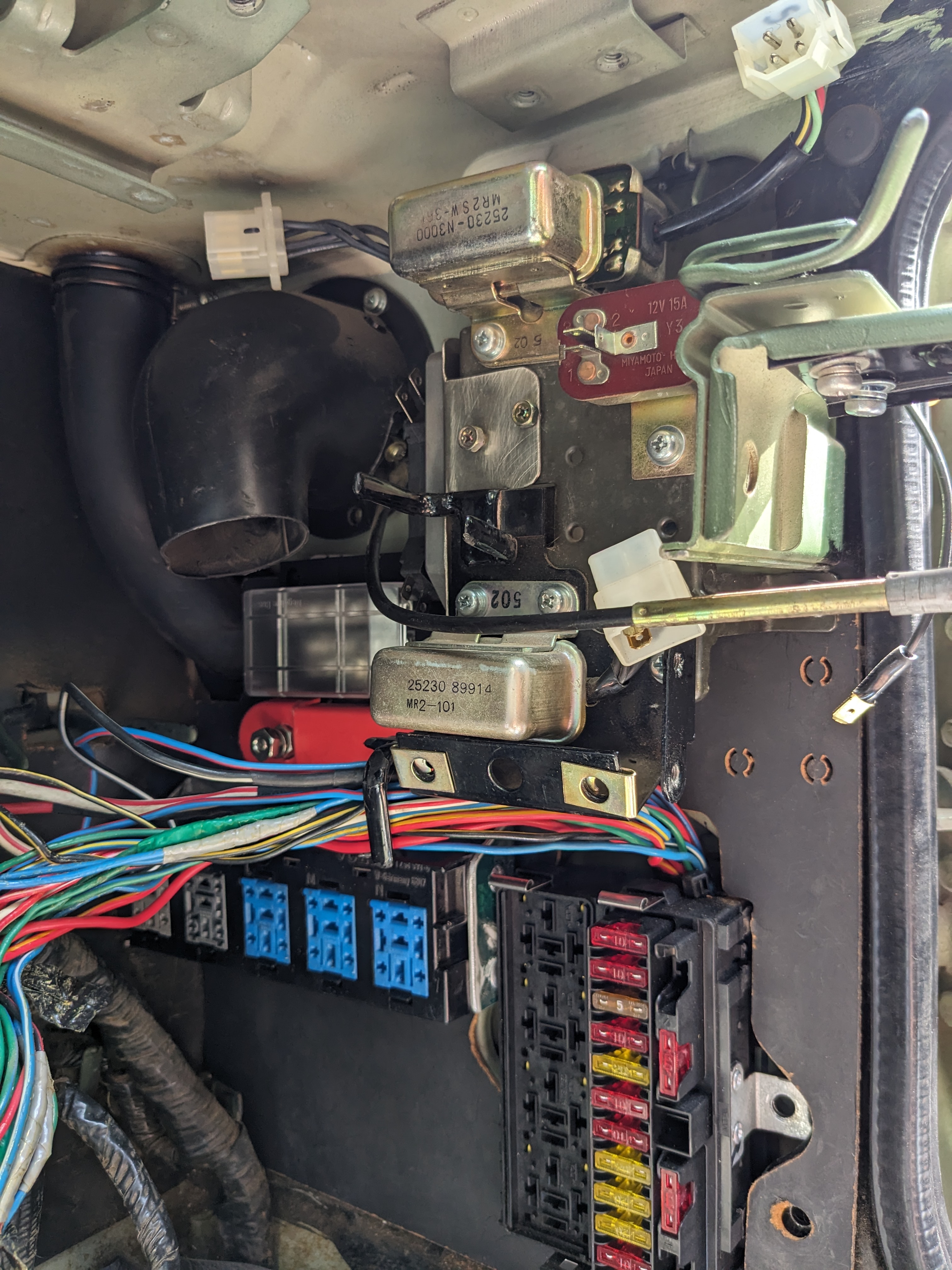
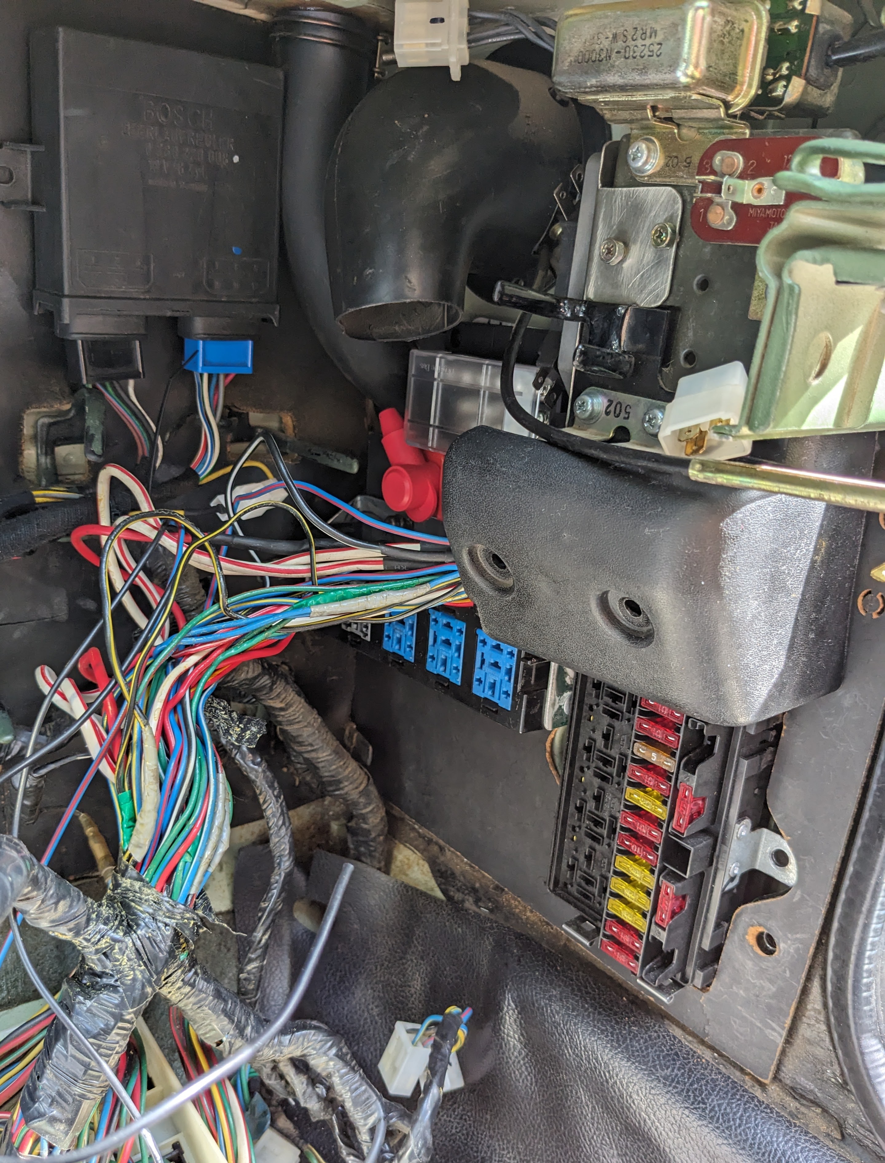
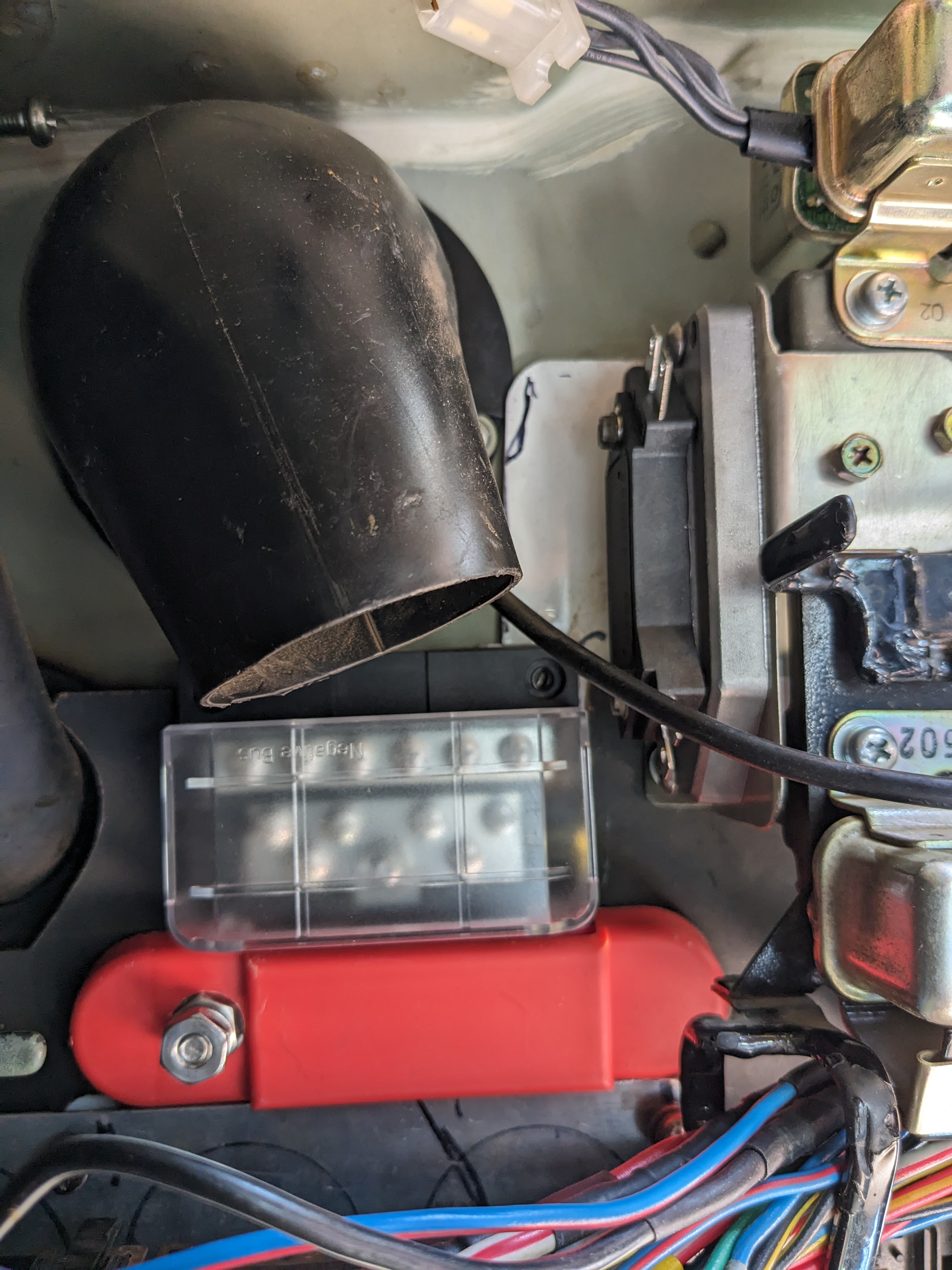
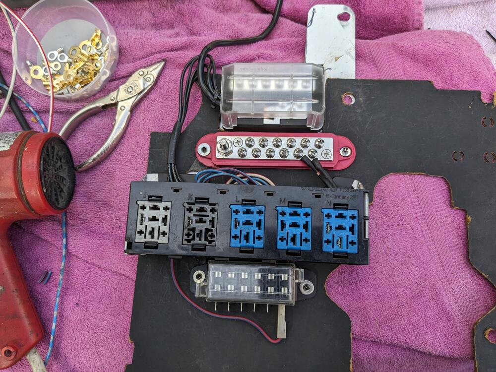
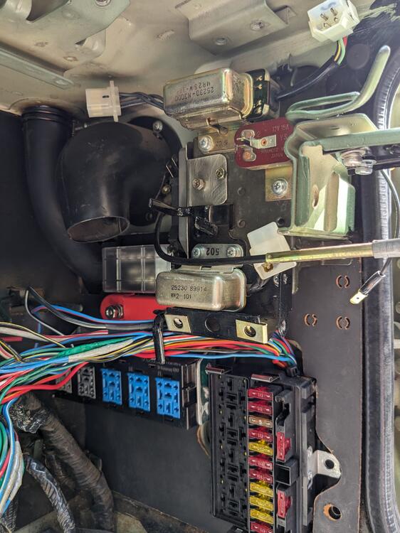
Added more stuff, to allow for expansion when I do the V6 conversion. Ground & power strips. Made a reinforcing plate that bolts using the stock mount points of the relay panel & ign module. Strips are riveted in place checking fit Stripped all the CAT / floor temp circuitry out while I had this apart added wiring for the seat heaters and WBO2 controller Have to deal with all the wiring at the console


-
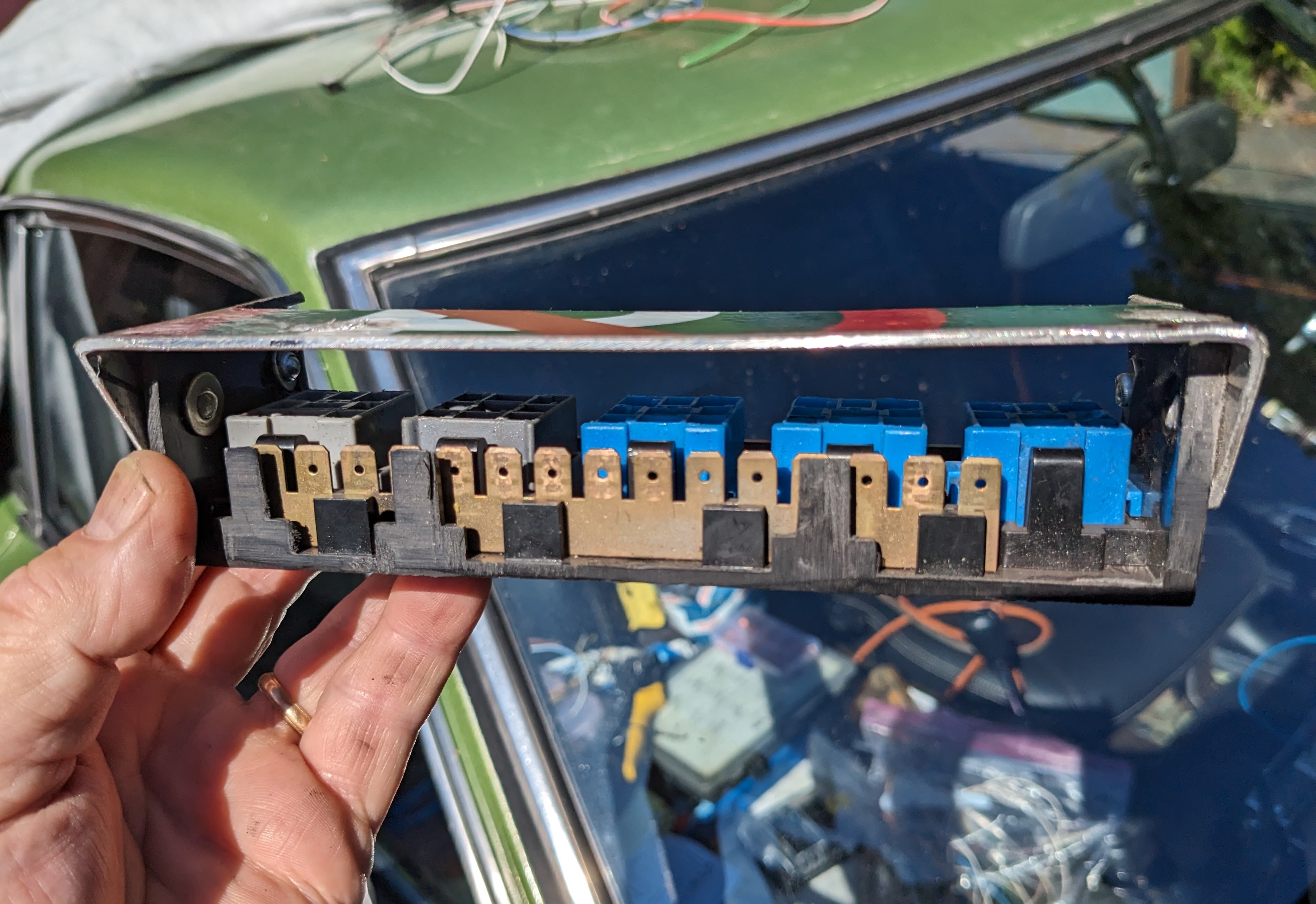
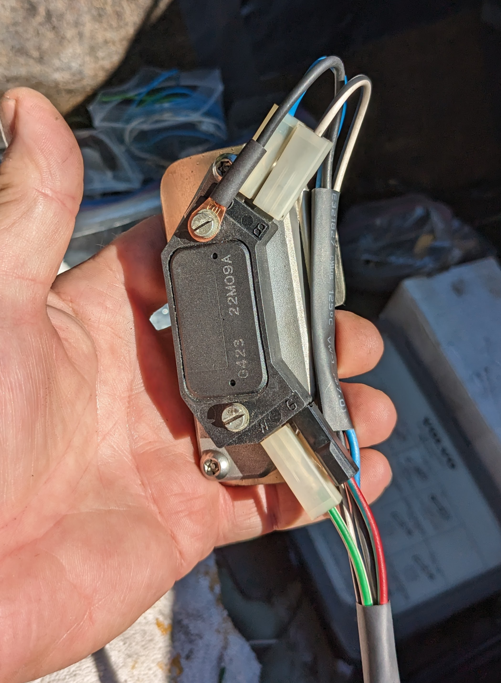
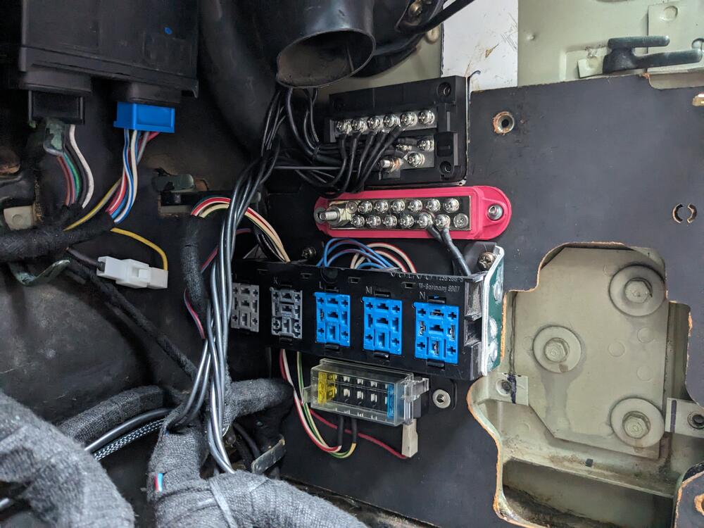
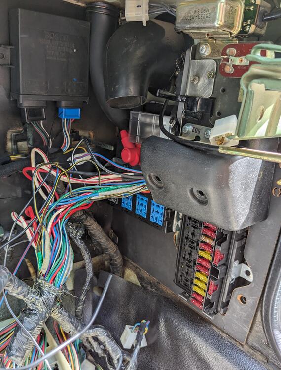
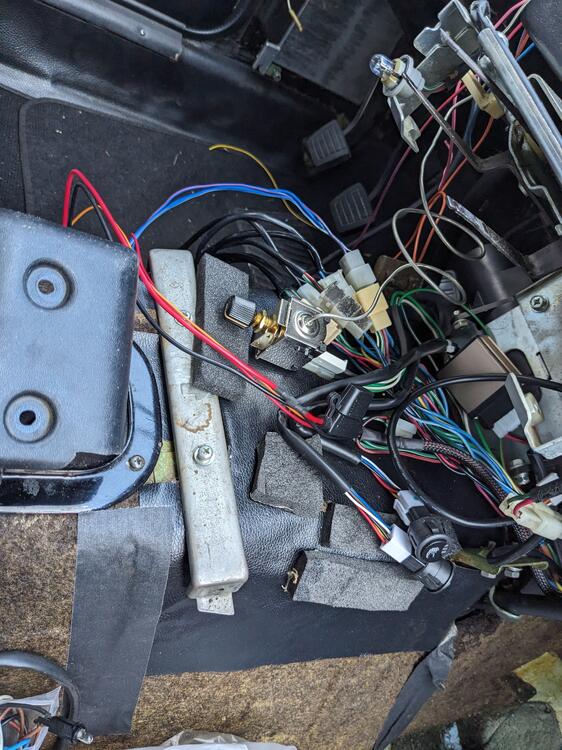
I mounted the HEI module/heat sink to a bracket I made, that attaches to the side of the stock relay bracket, where the interval relay previously lived. Made it so the assembly is unscrewed from the face, as the bracket screws are otherwise inaccessible. I'll make a sub-harness so that the module can be removed with that attached


-
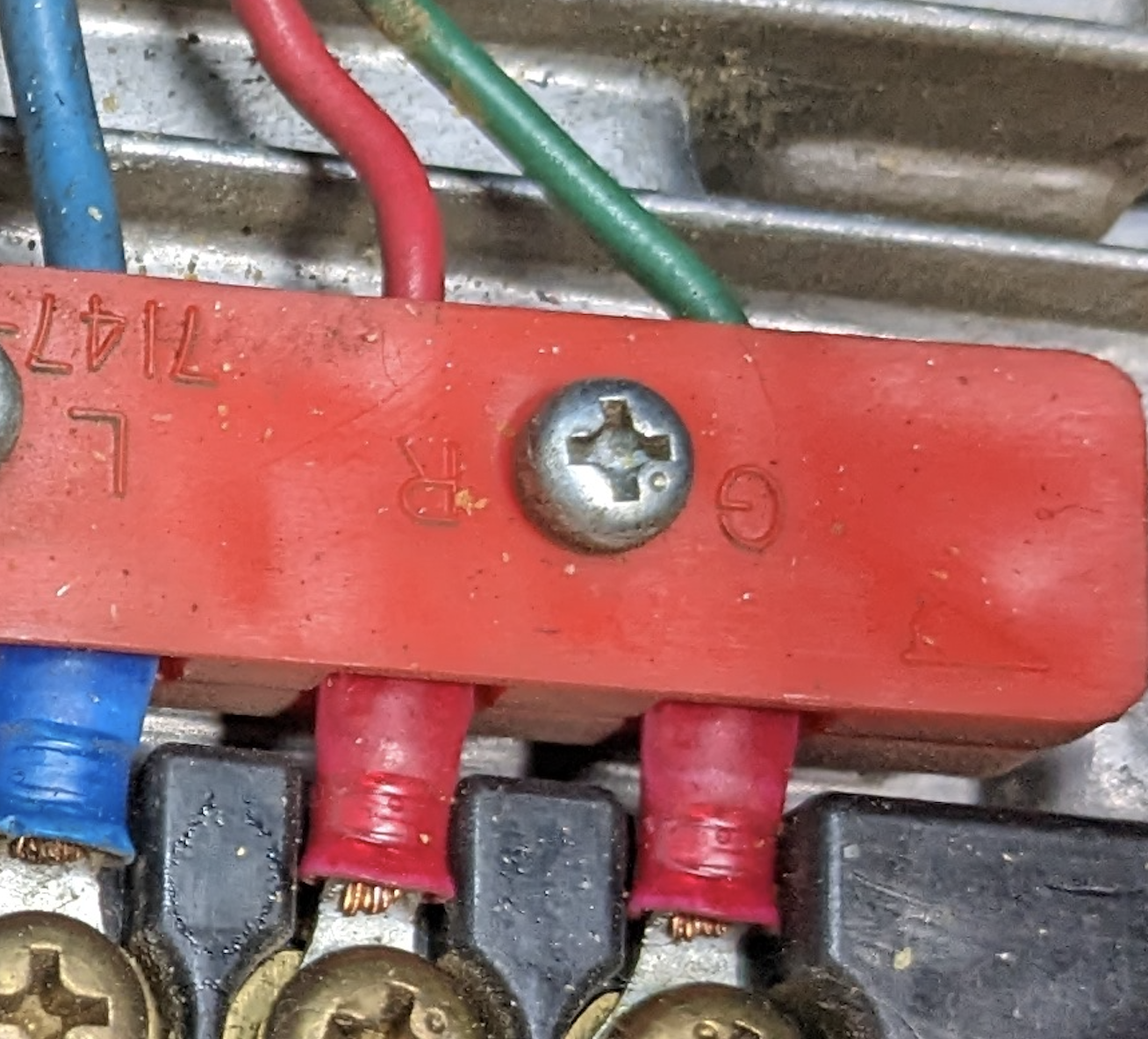
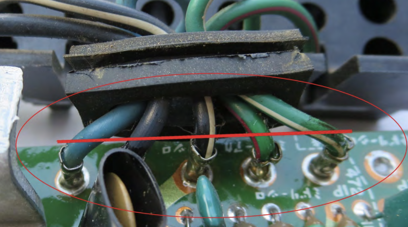
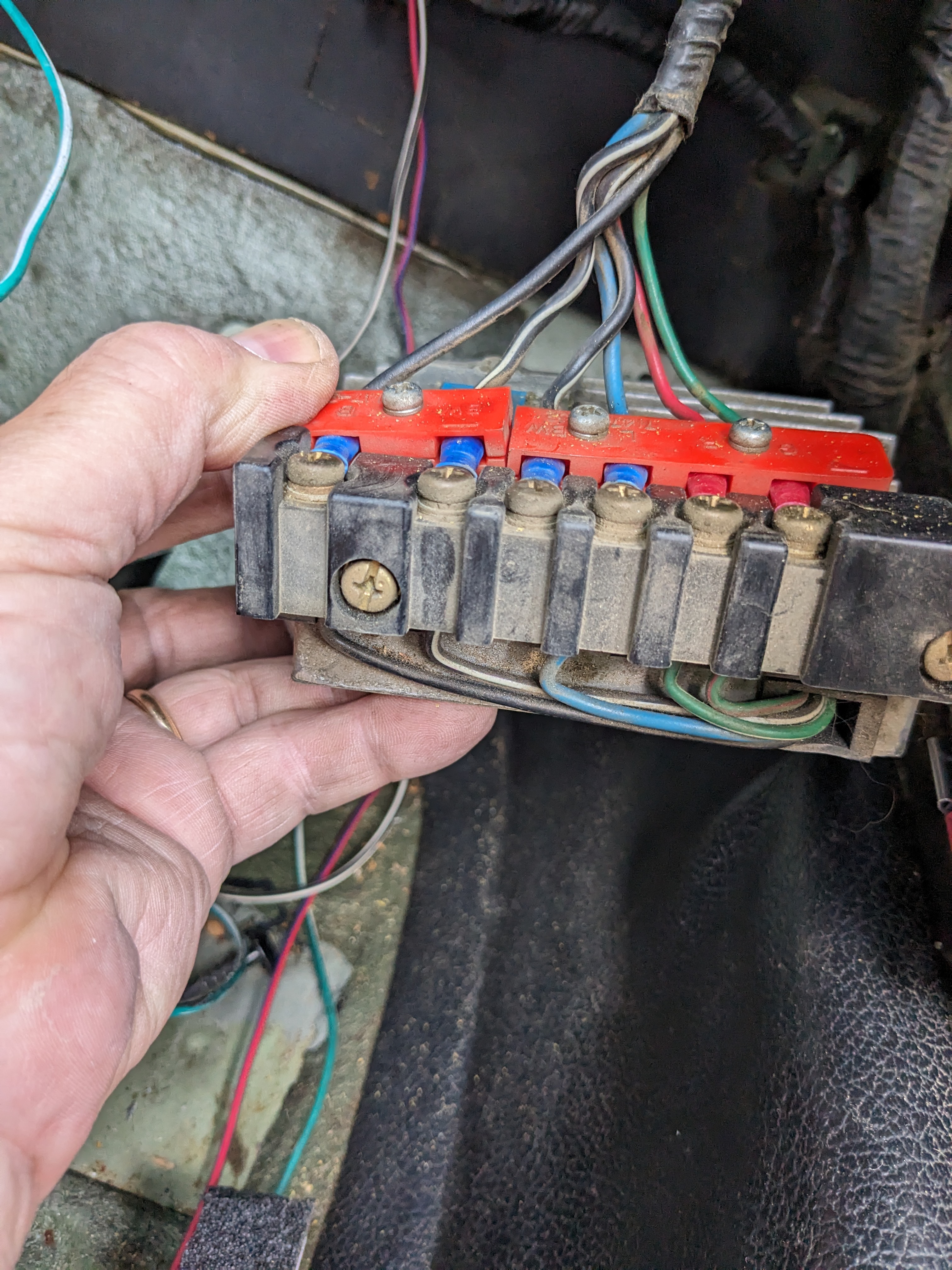
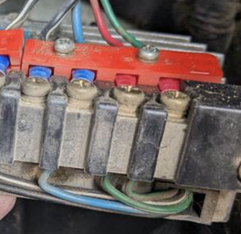
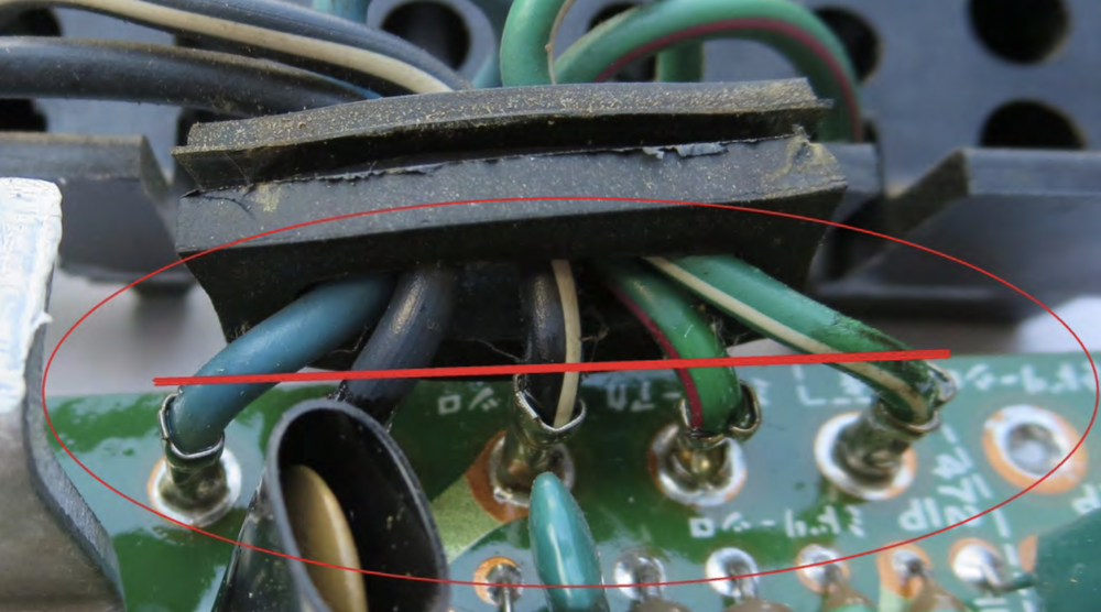
I see the G & W on his, I just have no clue what he means by W... Not sure what you mean by having it backwards though - the Gn wire goes to Green-Red on the module side, the Red goes to Green-White I am aware of the labeling on the wire retaining strip, I just didn't know if it was a difference between CA market & others, since there was another poster who said he had to reverse the wires compared to the same pic of his with the red on the outside... Crop of his pic from directions

-
Thank you. On a side note, reading the FSM diagrams drives me nuts, since the wiring illustrations are from the terminal side of any given connector, compared to European format which is always viewed from wire side of any given connector. I'm already good at getting dyslexic with wiring, having to translate the pin locations in my head from the diagram to the reality just adds to the potential for error on my part. I always double-check my wiring anyway, with these it just takes even longer. OK - So I'm going to assume the pin configuration he illustrates is still accurate for the HEI then, with Gn going to the small leg on the HEI He doesn't actually list or show the physical wire transfer/connection within the module to the HEI pins: G (harness) = Gn-R (module) R (harness) = Gn-Wh (module) Mine has 2 Blk/Wh wires, middle one appears to be redundant - since there is no connection on the module side. Not sure if I should join the 2 together for the HEI, in case there is some reason the 2 are required.
-
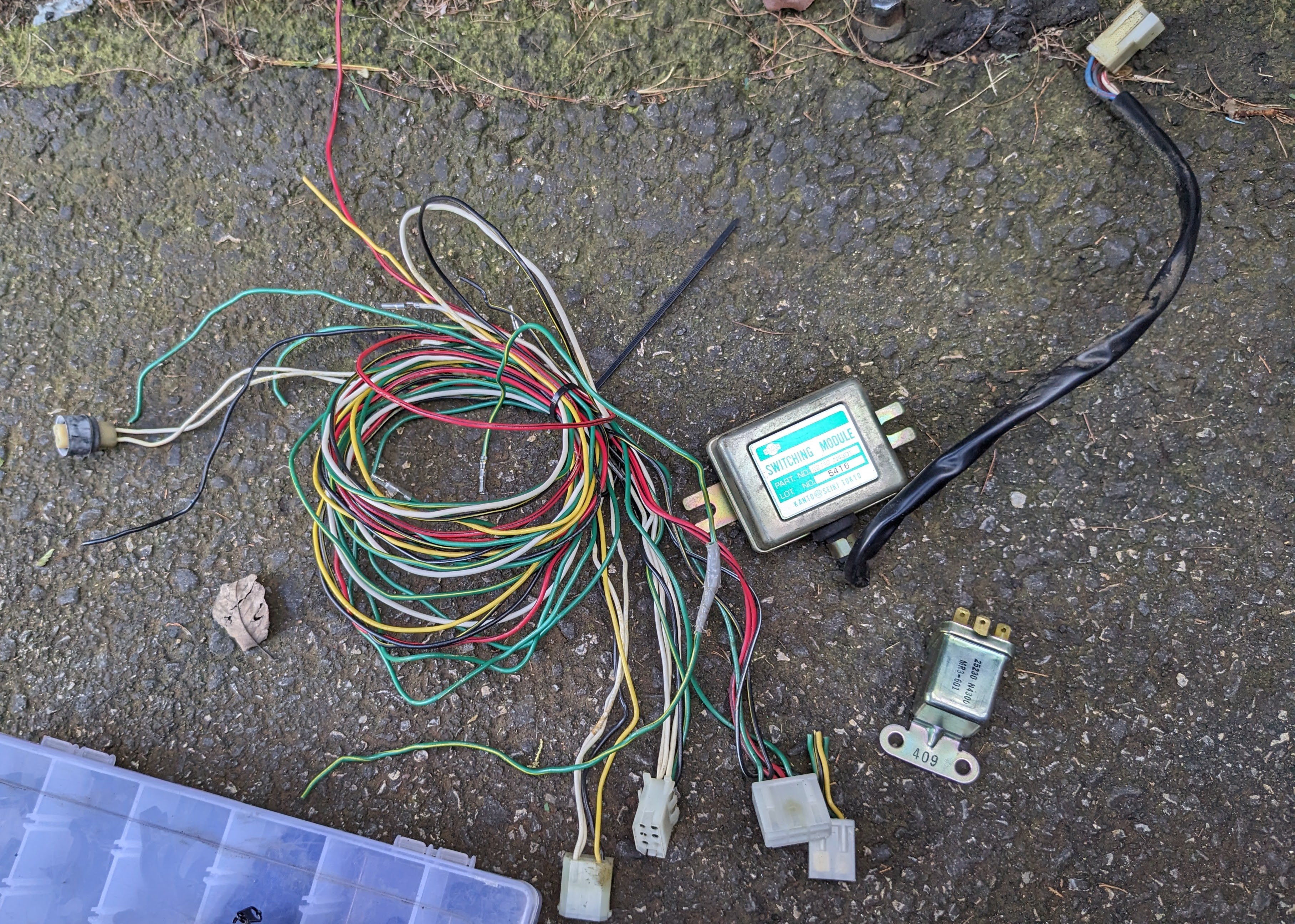
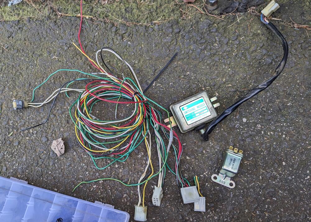
@EuroDat - I removed my module today, and the wiring of the red & green is reversed compared to your directions. Mine is a CA market 75 280Z