HusseinHolland
Free Member
-
Joined
-
Last visited
Everything posted by HusseinHolland
-
 Had a few hours after work, so I focused on fitting the Skillet grille & the front bumper & brackets, after I replaced the 3 pedal pads Brackets in first, then test fit bumper With the bracket alignment figured out, I worked on the Skillet grille. 4 brackets are loosely fitted to the grille prior to mounting. I bought the full grille, not the bumper version, as that version has large cutouts on either side. I cut narrow slots to allow the bumper brackets to pass through Then I put the bumper on before I ran out of light. The fit is really nice. 4 M10 studs secured through the brackets with 17mm head stainless nuts. I'll put the spoiler back on tomorrow. The only catch with doing it this way, is that the valance has to go in after the grille, so the 3 mount screws , and then the horns have to be fitted from above. There are small bumper blocks that I also bought from ZcarDepot (800-924). A M6 bolt passes through the fender & into a captive nut in the bumper
 -
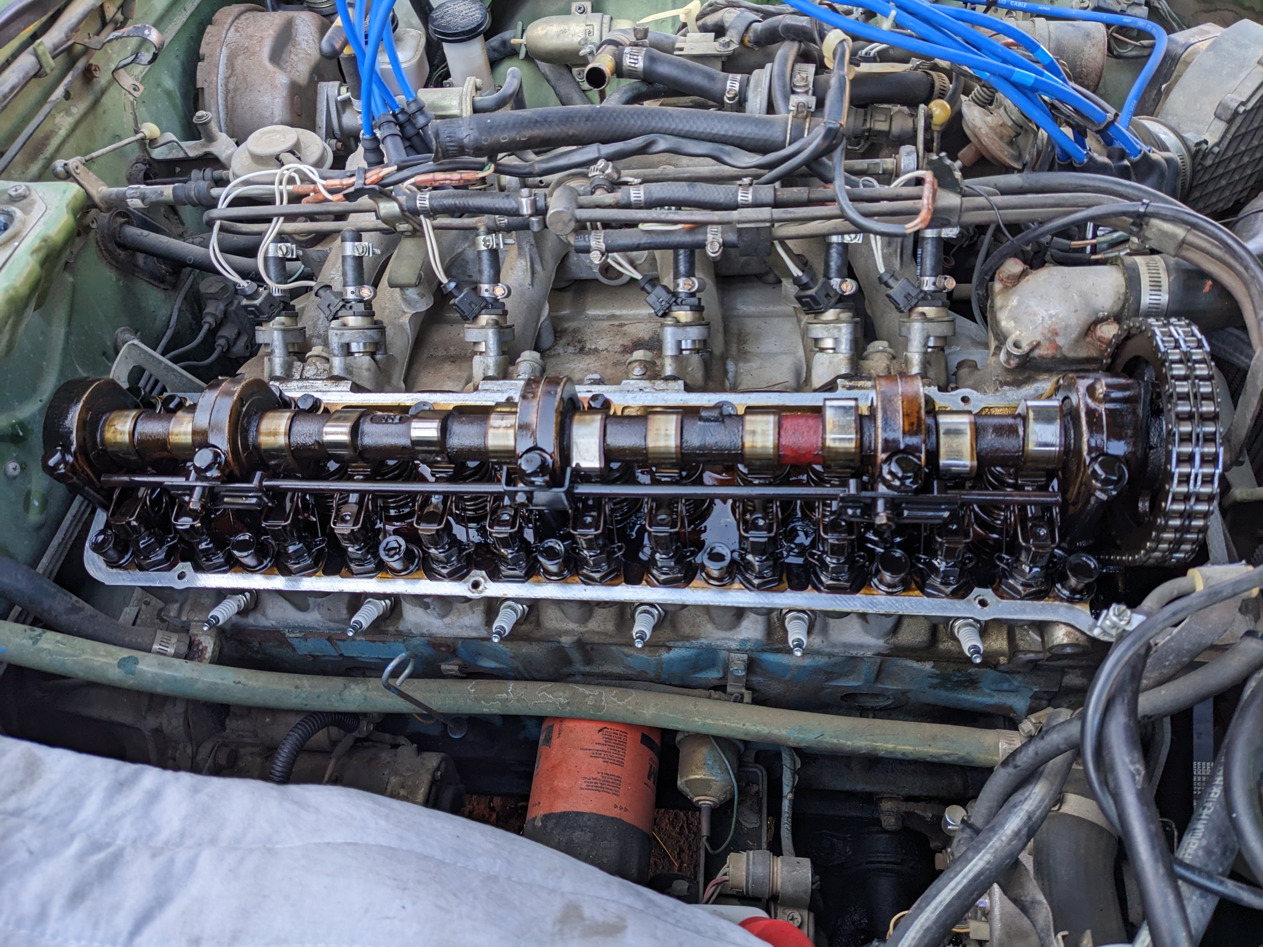
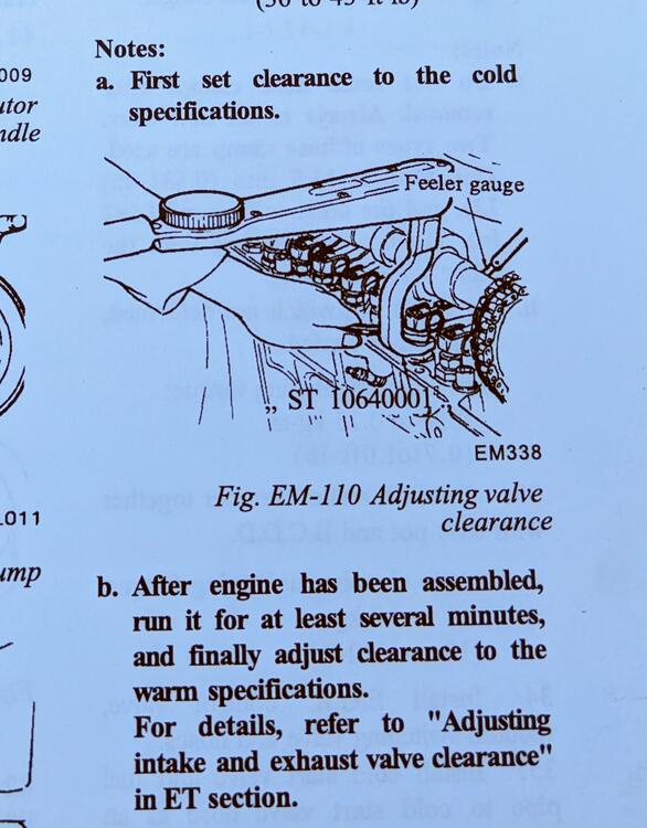
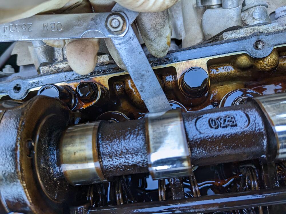
Yeah, the motor has 250K miles on it. I'm surprised the compression is as good as it is, really. I'll recheck it after loosening all the valves back into spec range. Thanks - So the large base nut (17mm) is the lock, then there is a 14mm? nut built into the shaft, I'm assuming, since it's tucked up against or under the rocker? I couldn't see it last evening. I'll look closer in better light. I'm used to MG/Volvo/Fiat/Honda layouts, which all had an obvious adjuster. I appreciate that tightening the lock typically reduces clearance, I usually shoot for the looser end of the clearance range when adjusting.
-
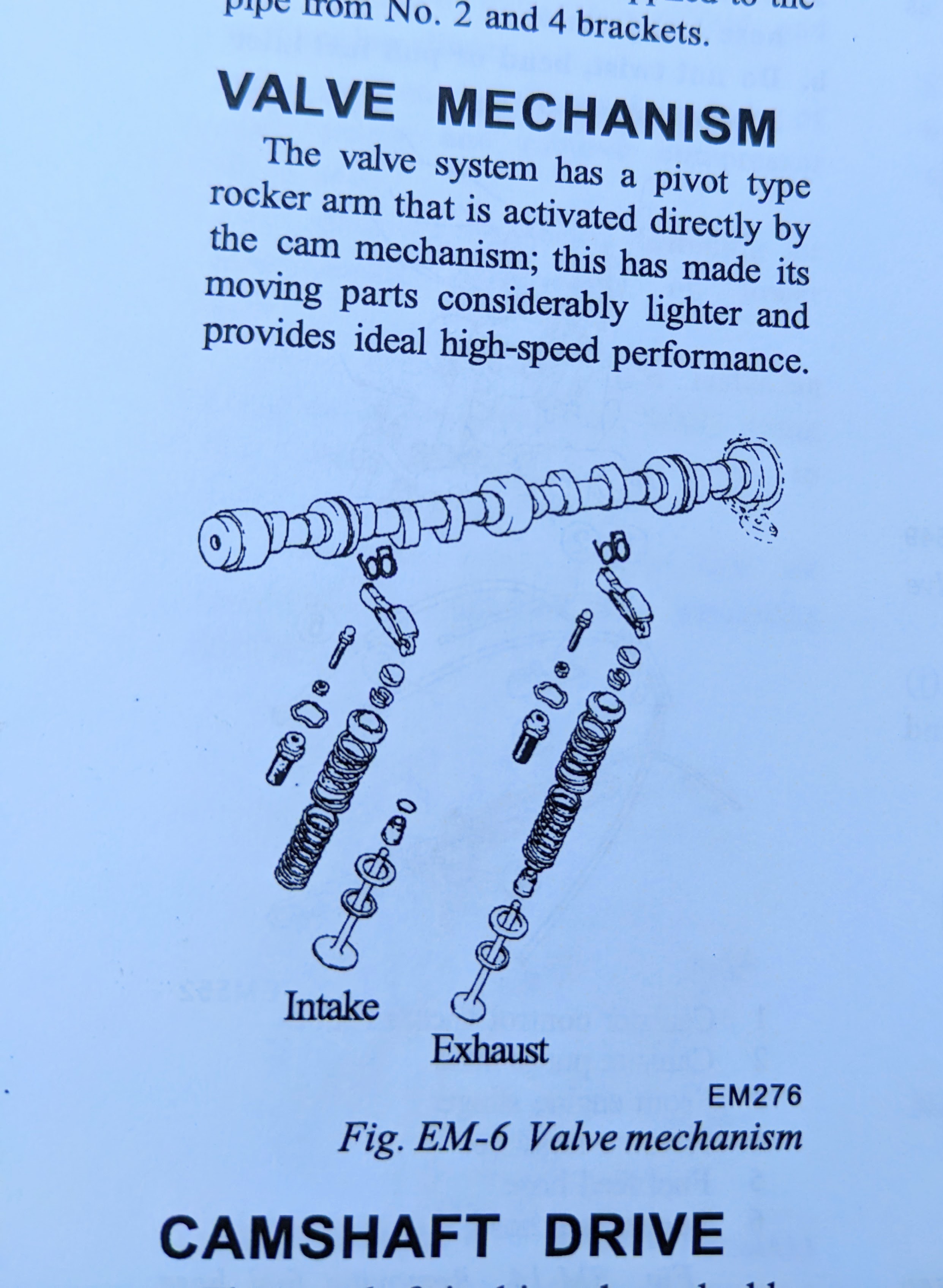
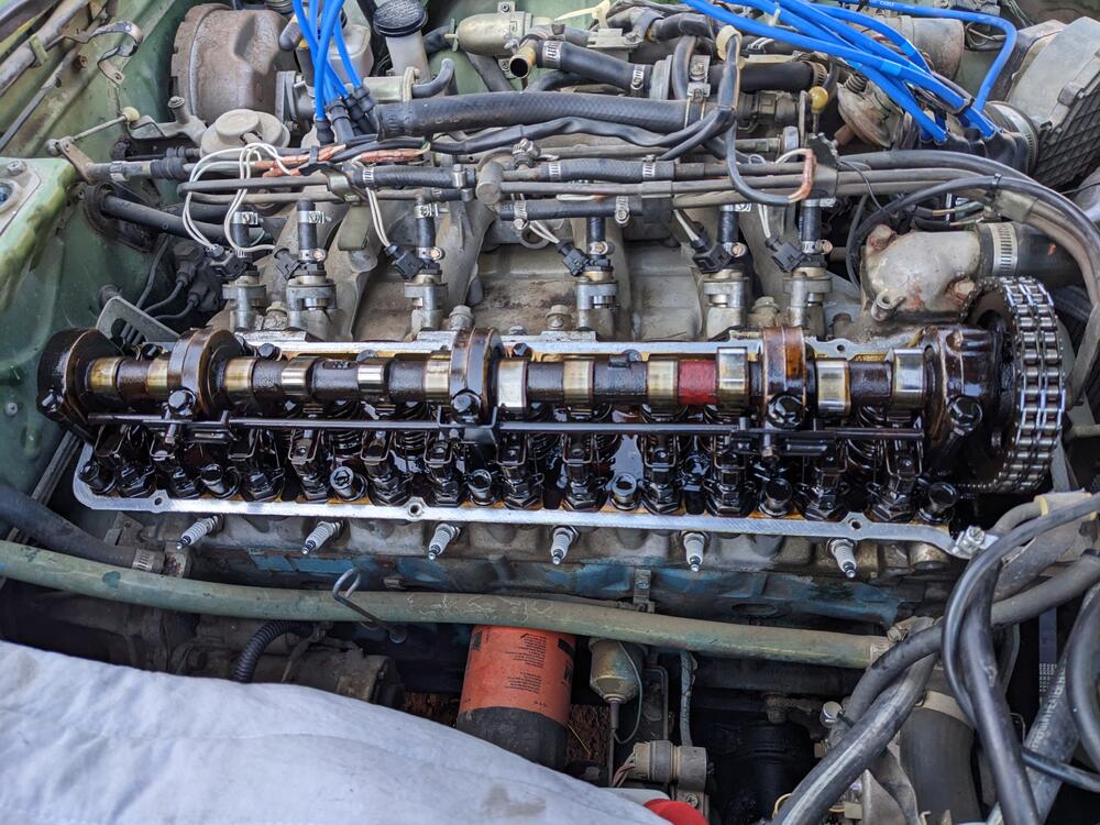
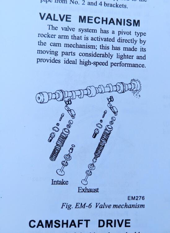
Any pics of the adjustment operation? The above tool set is helpful - The Nissan 75 manual has no detail on the process, that I can find beside this pic in the Engine Mechanical section I tried to figure it out from the pic of the valve layout. Not clear to me, besides that the 4 elements on the left are the adjuster Mine are all way too tight - can barely get a .010" feeler in there (checking #5 exhaust here, as that cylinder only had 145psi vs 168psi on the other 5)
-
In all the video installs I looked at, they seem to have issues with the spoiler dropping/warping - the 280Z has a valance that the spoiler sits against, if you don't remove it.. Clamped the middle to secure it, marked & drilled the 4 outer end attachments. Instead of futzing with nuts & bolts, I just used M6 stainless rivnuts & M6 sems screws For the leading edges, I used plastic body clips instead of bolts Added two rivnuts to the center section to anchor it All together (for now). I have a tall Skillard grille coming, and chrome skinny bumpers to complete the look. Ultimately, the spoiler will be body color. Added tape to where the bumper trim bolts went, covers up the extra unneeded holes. I'll make some brake ducts, so those cutouts don't look out of place
-
I saw this thread last week, and ordered a pair off Rock Auto for mine. Not here yet.
-
I'm going to have to work on the HVAC in my newly acquired 75 280Z - the PO said the core leaks. I'm reviewing your Escort core mod for that (so far the pics are all dead, but only on page 2). As far as this mod goes, you don't mention the heater control cable, does that mean you used the stock cable & re-routed it out the firewall? I do like the idea of the valve being out of the dash area.
-
-
-
As an aside - I'm actually English - moved to the US when I was 19 - I used to own & work on British cars after I moved here. I was quite insulted by the joke at the time. It did seem to be true unfortunately.
-
There is a saying in the US - "why do the British drink warm beer? - Because they have Lucas refrigerators" 🤪
-
-
Any double function (assuming you can find one) relay is going to take up as much physical space as two standard relays. At that point it makes more sense to stick with the factory setup. You can buy 'gangable" relay sockets for Bosch style Micro and Mini relays, so you can keep it pretty compact space wise.
-
Indeed. Since the Nissan EFI has the ignition pulse to the ECU, there is no reason to use anything complex here, just a question of single or double throw.
-
The only question I'd have is whether the standard micro relay rating (25a) is sufficient for an external fuel pump. It may be safer to use the standard cube/mini relay for that?
-
Nice! Although no Volvo ever used that relay - looks much the same as the one Fiat used for it's L-Jet in the 80's though. Personally, I'd look to update to a less expensive controller, if mine were bad. I'm of the mind that if it ain't broke don't fix it for most things, however if I need to do any rewiring on mine, I'll probably go with a less costly 2 relay setup
-
I haven't reviewed the Z EFI wiring diagrams yet - however, if the system relay requires an ignition pulse to trigger the injector ground circuit like most Bosch EFI, then there are various relays that can do that. This Volvo-based page (about half way down) has details on using a VW relay - 321906059C, 321906069D, 321906069G or 321906069H. There is discussion of timed pulse for the pump(s), since that is a feature of the LH systems Volvo uses. Perhaps that will serve your needs?
-
Yes, the function of the fusible link has been wrung out over the whole thread. It is also known that the heavier rated fuse types were not in production in the early 70s. The PO of my car (owned it from new) told me he had issues with the links. Who knows what rating he was actually given, and whether it was appropriate for the '75 spec. I'm just going to go with the equivalent ratings (40a = green, 80a = black) based on the chart I linked. I see no reason for concern. If I were interested in keeping the car completely original, I would source the appropriate wiring. I can appreciate that there are people to whom that matters.
-
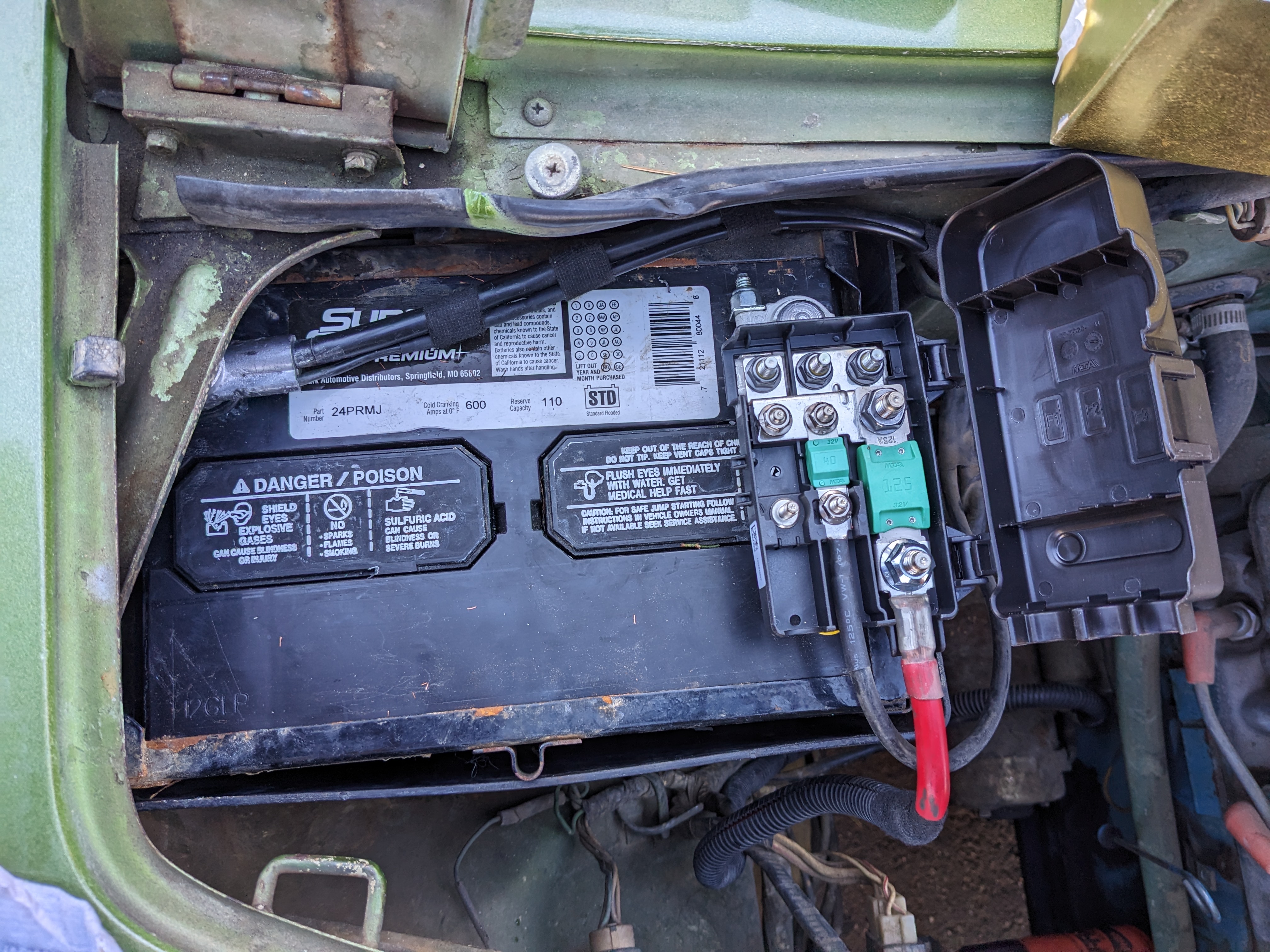
Thanks. I'm really not concerned with the fusible link features, just the amperage. I'm going to use a Midival block , which is very much akin to the primary fuse circuit on my Volvos. I may use one of the battery mounted blocks if there is room I'm used to rewiring/adding circuits. On my Fiat X1/9 I had to completely rewire for a Honda EMS, which required adding a couple ancillary fuse/relay blocks
-
Thanks so much for the link! I read through all 7 pages hoping to find somewhere where the fusible link ratings were translated into amps - the previous owner of my 75 280Z has been telling me they are 'fussy'. I'm more than happy to update this & add the H/L relay mod while I'm at it EDIT - adding the amp rating cross reference link HERE 🙂
-
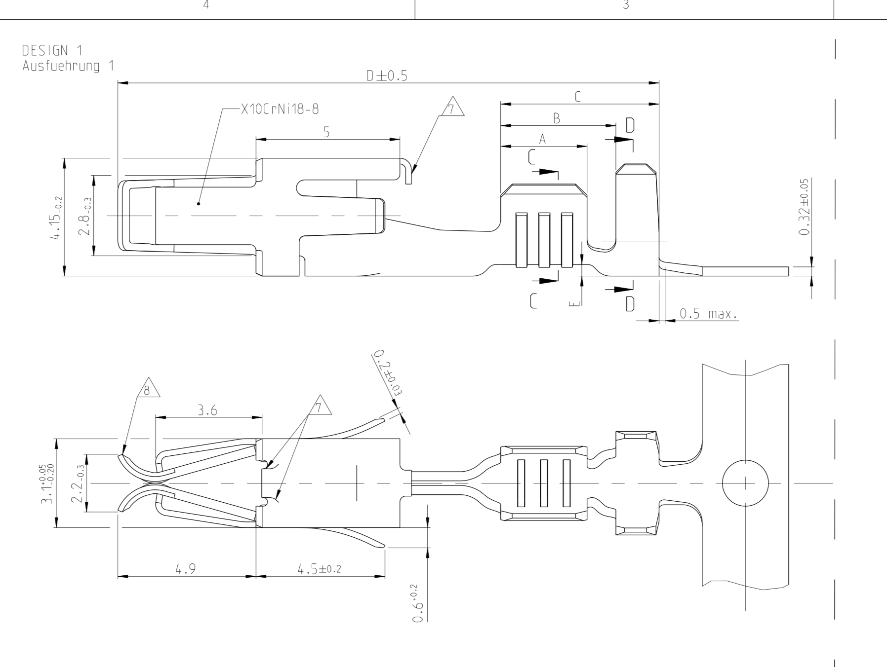
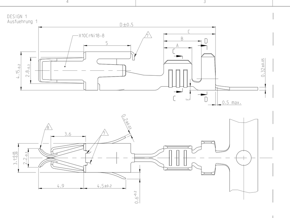
Not sure that takes a difference in terms of the std JPT terminal/receptacle connection. I have many Bosch (Volvo) LH ECU's, I can check the male tab dimensions for reference - they all use JPT receptacles for the harness connection. Do you have a picture of the receptacle housing Nissan used?
-
Hello. Curious if you have any pics. My 75 280Z is not with me yet. I'm assuming I will be doing some wiring updates, as things like the injectors have been butt-spliced. I've assumed all the terminals are JPT, since the FI system is Bosch L-Jetronic, or at least a licensed copy thereof. The male terminals are all 2.8mm, the female would certainly be wider if you are measuring the 'tang' width. Are you using the revised terminals with the spring tab sleeves? Example: TE 964286 I usually get all my JPT terminals from Mouser, however I have stooped to buying some off Aliexpress. Those are not always to spec. Just to provide some context, I am very familiar with extensive wiring mods. I had to fabricate harnesses for the Honda K24 drivetrain into my '87 Bertone X1/9, and for the ongoing LS1 swap into my 91 Volvo 740 (converted to pickup). I keep an extensive supply of terminals & use the proper crimp tools