.JPG.cfcada9cf1c1b502df3f5f2f2ca3ff36.JPG)

SteveJ
Member
-
Joined
-
Last visited
Everything posted by SteveJ
-
 I think it may be a change in business priorities. I met Steve Richardson over 25 years ago. I believed he was the manager of the parts department & Z enthusiast, and that was the hey day of buying Z car parts from them. I noticed the inventory of unique parts faded after he left. Without a champion in the parts department to support the older cars, it can be a tough sell to continue the effort.
 -
We can hope that temporarily means temporarily. Meanwhile there is still Nissanpartsdeal.com and Nissanparts.cc. You can also try https://www.lynchburgnissan.com/parts/center.htm#parts-lead-form
-
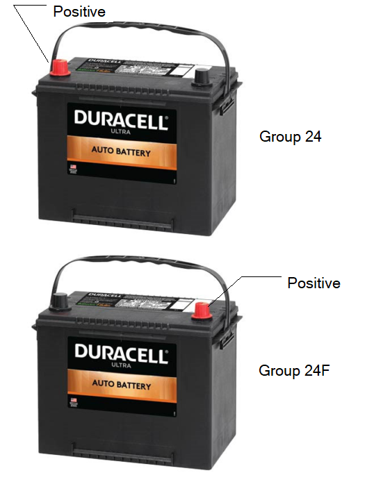
The difference is where the positive terminal is located.
-
The compatibility charts are designed for stock replacement. They don't account for things like using a hotter or colder plug. Amazon gives the incompatibility warning when I look for H4 headlight housings for a Z car. However, I can assure you that H4 housings worked in all of the Z cars I have installed them in.
-
It is a PITA to remove the speedo with a dash cap. You may have to trim the cap with a dremel to get it out the front. I wired up Speedhut gauges in a 280 after the owner mounted them. The issue is that you still need to get the old gauge out. Then you have to decide how far you want to take replacing gauges since some of the ancillary features like the high beam indicator and brake idiot light are in different gauges IIRC. Still I wouldn't discourage the use of Speedhut gauges if you know what you're getting into.
-
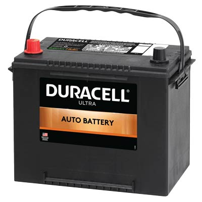
Group 24 batteries are standard. That puts the positive terminal under the inspection door where it belongs. Amongst other reasons, I think the most important reason for keeping it this way is that you should pull the negative terminal off the battery any time you are trying to disconnect the battery for replacement, removal, or servicing the electrical system. I won't put a Group 24F battery in my Z cars, especially after I had a mishap from not securing the battery properly. I also suggest getting a battery with a flat top if possible. I'm pretty sure that the stock battery bracket would work better. I will probably test my theory in the next month or so. Batteries Plus carries this Group 24 battery. It's more than the Walmart batteries, but I found the Walmart batteries to be hit or miss when I use my battery testers. One holds up fine after 2.5 years, and the other registers replace now, though it still has enough power to turn the starter and fire the car.
-
-
I think there is an STL file for printing nubbins buried somewhere in this thread:
-
Nice glow. Does Cody need me to find H4 housings and bulbs for the Goon?
-
It took me a little time to find it.
-
Post it in Google Photos as an album, share the album, and post a link to the album. Then I can make it into a PDF.
-
Well, the person I reached out to has not seen the Jims since Branson Z Fest. That was over 7 months ago. 😟
-
Don't forget to get a good set of LED headlight bulbs to make those H4 housings work well. I like the Auxito brand. These can be used with or without relays. https://www.amazon.com/AUXITO-H4-Brighter-9003-Replacement/dp/B0CLG3WZ8S
-
I would expect the center post would have continuity through the cable, but I could be wrong. You could always set up a test rig to test it out or just buy a new cable and run it through the car. You can get a 20 foot or 15 foot cable on Amazon.
-
Dash part numbers: 24013-N3300 MANUAL 7207 7209 24013-N3301 AUTOMATIC 7207 7210 24013-N3325 MANUAL 7210 7307 24013-N3326 MANUAL 7210 7307 24013-N3327 AUTOMATIC 7210 7307 24013-N3328 AUTOMATIC 7210 7307 What the difference is between 3325 and 3326, I have no idea.
-
And to answer the second part, 24013-N3321 and 3322 are dash harness part numbers. By the way, you might want to reach out to Junkyard Jenny - https://junkyardjenny.com/ to see if they have the harness you need.
-
Engine harness: 24012-N3300 MANUAL 7207 7302 24012-N3304 MANUAL 7303 7307
-
I'm not sure what year your Z is. Up through 76, I believe the specs are 60 L for fuel (15.85 US Gallons) for the North American model. I would assume a 77 or 78 260Z (if they exist in the UK) would have the larger tank like North America. The problem is that I don't think the sender does anything to account for the shape of the tank. I'm not sure if the adjustment screws would help, either. The top 2/3 has only about 1/2 the width of the bottom third. To simplify things due to the fact that I have a simple mind, we can model the tank somewhat like this: So the darker grey top half is about equal in volume to the light grey bottom half. Since the tank is 60 L, that means each portion is 30 L. That means 15L would be 1/6 of the way to the top of the tank, and 27 L would come up to a little under 1/3 way. It looks like the gauge readings are somewhat consistent with that.

-
I'll try to remember to reach out to a Z person in that area to see if he has heard from them.
-
Male to the front & female at the antenna.
-
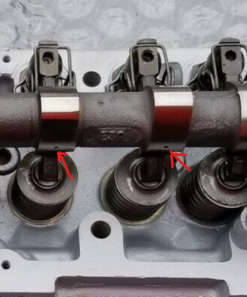
Actually, if you take the car out of gear (assuming it's a manual), connect a remote starter with decent sized wires (not the cheap Harbor Freight version) to the solenoid. (Here's an example of one:https://www.amazon.com/INNOVA-3630-Remote-Starter-Switch/dp/B000EVU8MK.) Take off the valve cover and crank the engine with the remote starter while looking to see if the oil is coming out of the holes. If there isn't enough oil coming through, you'll be able to tell by the grooves in the cam lobes. 😬
-
Yes there are holes in the lobes just before the lobes make contact with the rockers. If your head doesn't have a spray bar, and the cam isn't internally oiled, you would have toasted your cam already due to the lack of lubrication.
-
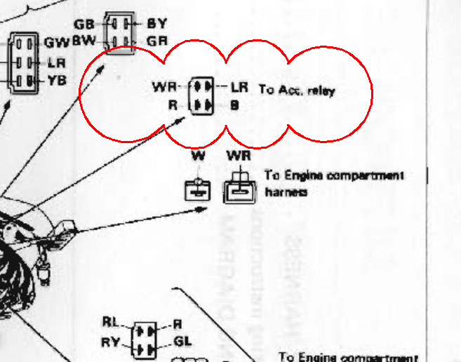
There are two ways to do the splice. You can crimp the wires together (typical for production wiring), or you can solder. If I was doing it, I would use the crimp connectors. I bought this kit last year for future projects: https://www.amazon.com/gp/product/B08XTV93GD. To understand the size of the crimp connectors you need, here is a handy chart showing wire cross sectional areas for a given AWG size: https://www.engineeringtoolbox.com/awg-wire-gauge-d_731.html. If you are doing a couple of 10 AWG wires, that would require soldering over crimping due readily available crimps being too small for two wires of that size. To answer your questions, you are correct. The red and black wires would pass through. That does look like the accessory relay in your photo.
-
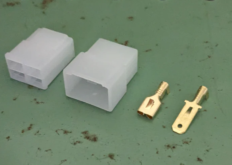
Here are my suggestions for power sources: Power door locks - Full time power Power windows - Accessory power 2 Power outlets - Accessory power Hatch popper - Full time power So now you need to know how to go about getting this power. I like to construct "jumper harnesses" myself. That is a short wiring harness that goes between two factory connectors that branches off to the new circuit. In the past I have used the "bullet" connectors in the jumper harnesses to branch off, but now I would add splices soldered into the wire of interest. In your case, there is a great connector to add a jumper harness, the accessory relay. The WR (white/red stripe) wire is constant power, and the LR (blue/red) wire is hot when the accessory relay closes the contacts. How would you make a jumper harness? Vintage Connections has most of what you would need, including wires with the proper coloring if you want to stay consistent with the factory colors. In this case I would suggest the following: A 4-pin non-latching connector 2 1-pin non-latching connectors (Note: you can also use 1 2-pin non-latching, but that is a discussion for later.) 2 inline fuses, probably sourced from Amazon, like this: https://www.amazon.com/Inline-VANTRONIK-Waterproof-Standard-standard/dp/B081YDV8PS for at the jumper harness and use the others for a couple of the branch circuits 14 AWG wire 16 AWG wire (for the power outlets) 2-pin non-latching connectors for each of the devices. 4-pin non-latching from Vintage Connections I would drop down the wire gauge on the power outlets and use 16 AWG on those. (Use 5 A fuses in the inline fuse holder.) I would use 10 A fuses in the fuse holder for the branches coming off the jumper harness. That should give your wiring adequate protection.
-
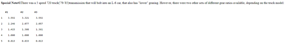
The 720 box isn't bad. I did find confirming information with your ratios, too. https://www.zhome.com/ZCMnL/tech/GearRatios.html