


.JPG.cfcada9cf1c1b502df3f5f2f2ca3ff36.JPG)

SteveJ
Free Member
-
Joined
-
Last visited
Everything posted by SteveJ
-
 Got it.
 -
I thought you said it was a 72. That year doesn't have any EFI components.
-
The parts catalog only lists one part number for the 240Z for the headlight assembly. The same applies for all of the parts in the sub-assemblies.
-
Are you sure they aren't swapped around or mounted improperly?
-
And if you're wondering where to get a new ignition switch (back portion) https://www.rockauto.com/en/catalog/nissan,1972,240z,2.4l+l6,1209169,electrical-switch+&+relay,ignition+starter+switch,4700
-
What do you mean by "no current"? I asked you to check voltage to ground. How do you know the swapped module is good? Could you tell if the key was turning the module?
-
Likely suspects include the ballast resistor, tachometer, and ignition switch. This diagnosis assumes the car to be stock. Put the key in the ON position. Use a voltmeter to measure voltage to ground at each terminal on the ballast resistor. If one side does not have voltage to ground, replace the ballast resistor. If neither side has voltage, the problem is with the module in the back of the ignition switch. If both sides have voltage, then lift the negative wire off of the coil. Measure voltage to ground on positive side of the coil. If you do not have voltage, the problem is the tachometer. Check to make sure the tachometer is firmly connected to the dash harness.
-
That's a red wire?
-
Green wire? That may be the EFI fusible link.
-
What year?
-
Well, the fuse is a 20A fuse. In my practice, I usually try to fuse 14AWG wire at 10A or less. If there was a dead short somewhere, most of the wire could have burned up before the fuse blew. You'll need to follow the breakouts in the BE section to see where you can still find voltage in the circuit. Start with making sure you voltage to ground at both contacts for the parking light circuit on the headlight switch. Work your way downstream toward the lights. While you said you replaced the headlight switch, did you test it to make sure it was good before you installed it?
-
Nope, it tells me you have some current flowing somewhere. Make sure your rheostat isn't turned all of the way down, making your dash lights dim.
-
In the BE section of the FSM, you will find a nice breakout of the "clearance" light circuit. Measure the voltage on the top right fuse with the switch off. If the voltage is good, turn the switch on, and measure the voltage. If the voltage dropped, you have a bad connection at the fuse box or probably the fusible link. See the discussion between myself and @Captain Obviousin this thread:
-
I stand corrected. I found a picture on this site for the turn signals on a 280Z tachometer.
-
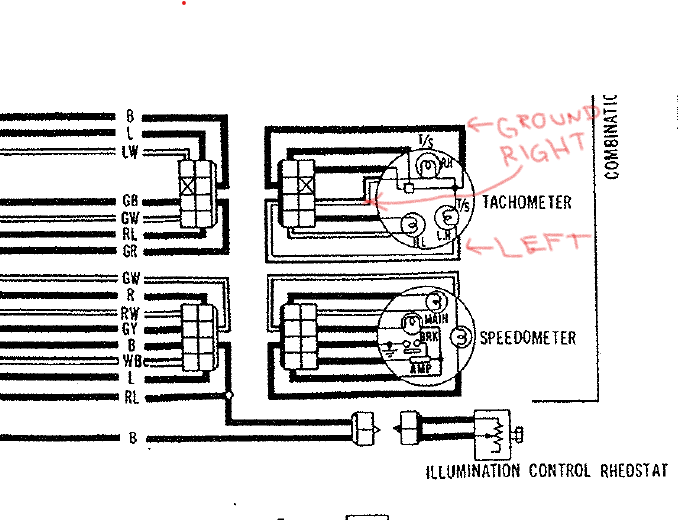
It is doubtful someone used a 240Z tach in your car unless the wiring was modified. Until you post photos of your tach with the light sockets and connector, I am going to stick by what the factory wiring diagram says about your car. The wiring diagrams the same for the 260Z through 280Z for the tachometer. I know the tachometer in my 260Z was wired per the factory wiring diagram.
-
It's quite likely your headlight switch. Sometimes the connector melts down. Sometimes there is melting in the switch. Sometimes the contacts in the switch get coated with carbon. Some of us have become skilled in tearing them down and repairing them.
-
That is for a 240Z. Your signature says you have a 280Z.
-
I suggest you modify your research to look at the factory wiring diagram. The turn signal sockets are NOT grounded on the meter body. There is a ground wire in the connector. The ground is common for the tachometer itself and the turn signals. Both the GB and GR wires come off the C-5 connector.
-
That's why I tell people to find the wire colors on the dash harness, engine harness, or body harness side of the connectors. I have seen/heard of many components using wire colors that don't match the main harnesses. Aftermarket voltage regulators come to mind.
-
The kit that @AZDatsun mentioned is the basis for the design I implemented. Now I'm looking at getting rid of some of the visible wiring from that conversion, including the relays in the engine bay. It's just personal preference.
-
The LEDs require 2 positives wires and 1 negative wire. The Z is wired with 1 positive and two negatives. Solutions for the 240Z are fairly straightforward. You can buy the relay kit from MSA, or if you have a 72 or 73, I posted directions on how to wire relays into those model years without cutting factory wires. The 260Z and 280Z do not present such an elegant solution. Currently, on my 260Z, I removed one of the headlight sockets and replaced it with a 3 pin connector to control the relays. I drilled new holes in the headlight mounts to wire in new headlight sockets that have 2 positive and 1 negative wire. I am working on another solution to eliminate the extra wires that I currently have behind the headlights. However, I am still waiting on some connectors. Any way you look at it, it is not a simple modification. If you don't have much experience with wiring, make friends with someone who does (and who can read wiring diagrams). Mind you, the halos may take additional wiring if they are supposed to draw from the parking light circuit.
-
-
Well, the female Molex terminals work on the male Yazaki terminals, and in a pinch, the male Yazaki terminals can be used in a 4 pin Molex connector. I did notice in my test fits that the 0.093 male Molex terminals were not that secure in female Yazaki that had been stretched. Other terminals in the same connector were more snug, but not enough for my liking. It's all about fractions of millimeters. With the higher current application in headlights, I went ahead and ordered some Yazaki connectors/terminals from Cycle Terminal. I did test fit the male connectors from the Yamaha connector kit I purchased from Vintage connections. It fits snugly, but I would have to crimp on a wire to see if it will lock into the Datsun connector. The locking pins are much smaller than the barbs on the Yazaki terminals, though, so I'm not too optimistic about locking into place.
-
In regard to the wiring the IPO put in, the blue wire is the power for the fuel pump relay coil. It's connected to the yellow wire that is shown in the wiring diagram between the voltage regulator and alternator. The blue wire runs from the yellow wire to the 85 or 86 pin of the relay. The curly wire runs between the 86 or 85 pin (whichever the blue wire is not on) to ground. The black/red wire is the power for the fuel pump. It is going to pin 30 or 87. The white wire is going from the 87 or 30 pin and on back to the fuel pump. With the way it is wired, if the black/red wire came off the relay while the car is running, it could cause an electrical fire since there is not a fuse between the alternator and the relay. As you seem to have figured out, the blue wire will go away after modifying the electrical system for an internally regulated alternator.
-
I hope we get an update at ZCON. Anyway, my daily driver can hold up longer if the Z is delayed.
