Everything posted by SteveJ
-
Restoration of 71 240z
Yep, my 240Z has been waiting on me for a few years now...
-
Restoration of 71 240z
Maybe he was thinking all Z cars were 2+2s.
-
Pin Extractor for Round Pins
I don't know if I can get to the headlight connectors before ZCON. You might have to hit me up in late September.
-
Pin Extractor for Round Pins
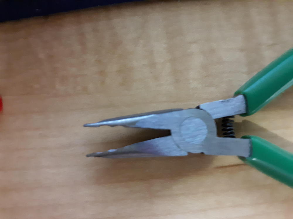
Okay, so I received the Molex pin extractor. It kinda-sorta worked, but the spring inside wasn't strong enough to push the pin through. (Don't get the spring loaded pin extractor.) I seem to have more success using a 1/8" brass tube with 0.014" walls along with my modified pliers. The brass tube is from K&S Precision Metals, part number 8127. Jim @S30Driver - Did you have to remove any pins from that project you asked me about?
-
Pin Extractor for Round Pins
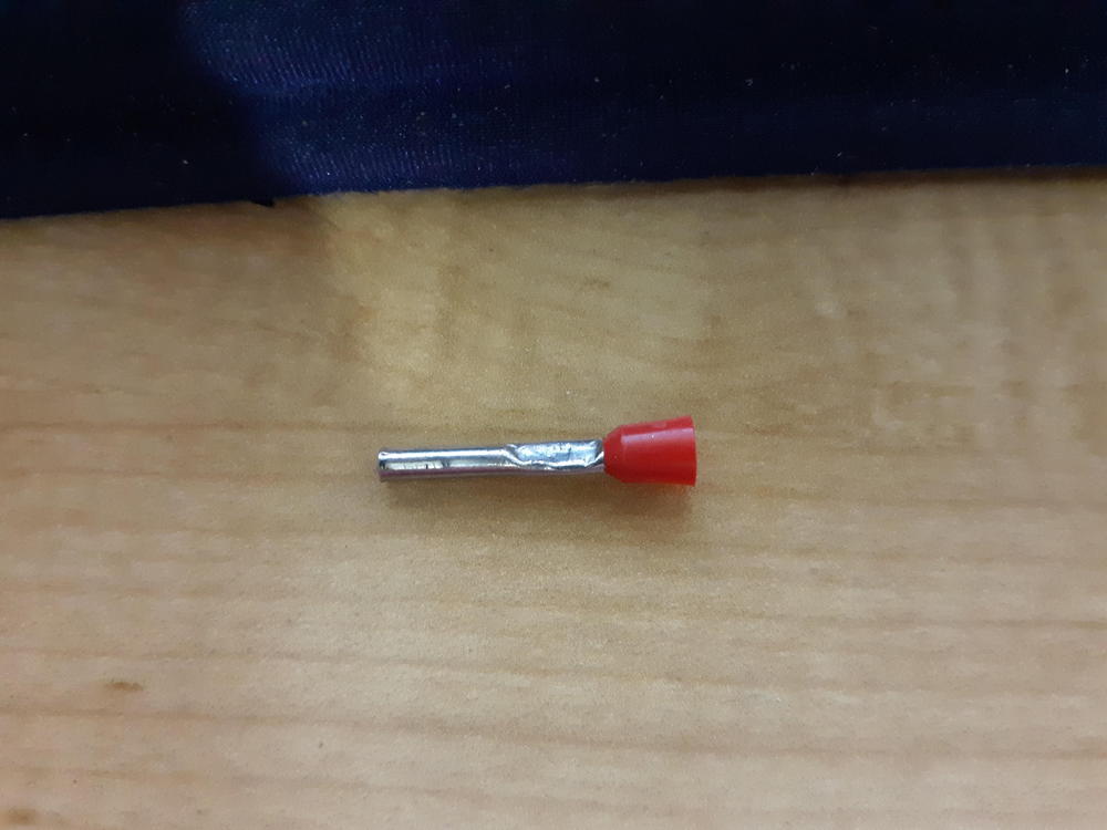
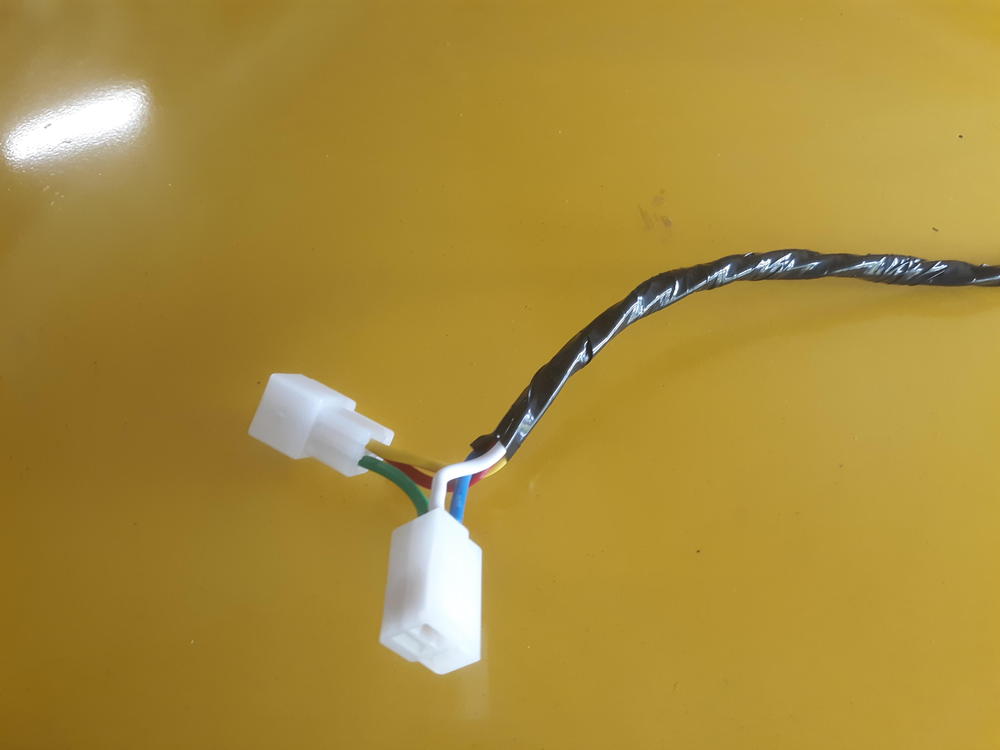
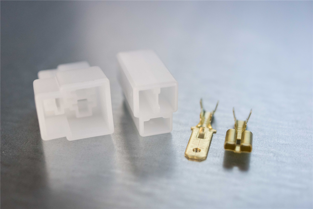
So, after playing around with measurement tools on the pins, I decided to order a Molex pin removal tool for 0.093" pins. It's supposed to arrive today, but since I can be impatient at times, I decided to experiment again with materials on hand. I have a "key chain" of pin extractors. None fit the 280Z pins, but there was one that was just slightly too small. I took a 3/32" drill bit and stretched the tube on the extractor. The crimped area in the photo is from holding the tube with pliers to remove the drill bit. I tested it on an old gauge, and the pin pushed right out. I tried another pin, but it didn't budge. That's when I figured that I must have been able to push the barbs in the pliers I modified. I tried the technique a couple of more times with squeezing the barbs with the pliers and following up with sliding the extractor over the pin to push it out. So next it was time to test fit the pins in the connector from Vintage Connections. Nope. It didn't fit. I ordered some Molex connectors from Amazon to try another experiment. I should see those by Friday, I hope.
-
240z (barely) runs very unevenly!
What does the dwell meter read?
-
240z (barely) runs very unevenly!
Is this the first time the car has acted this way? Did you verify the gap and dwell on the points? Does it only happen under load?
-
Pin Extractor for Round Pins
I'm trying to find the right size pin extractor to remove the round male pins from the connectors. The size appears to be the same as a Molex pin. (0.093" or 2.36 mm). Has anyone on here found a good pin extractor for these? I am hoping to design a headlight relay solution for the 260Z/280Z that will be of similar elegance to the solution I created for the 72/73.
-
280Z Parking Light Circuit
Yep, I documented the C-2 connector in my notes to my customer. I try to have a work plan ready for paying customers so I don't rack up a bunch of hours on random diagnostics. The white/red wire feeds many fuses in the fuse box. My customer had another shop put in a disconnect switch due to a battery drain, so I used my ammeter to track that down. (Fix the problem, and don't use a bunch of band aids.) I traced it to that branch in the fuse box, and we removed fuses to see when the current draw ceased. That took a while because the draw would come and go somewhat randomly. Eventually I found that the passenger side door switch was wonky. There wasn't easy access to disconnect that switch, so we just pulled the fuse for now since he was not worried about the dome light or other lights on that circuit. I'll have to look at the other circuits in C-2 to see if there are other indicators of corrosion. The terminal for the parking light circuit could have overheated at that connector. It's not like I haven't seen damage to a lot of fuse boxes and wiring for the parking lights. The nice thing is that he is willing to get his hands dirty and does not mind providing assistance since that reduces the number of hours I charge. He seems willing to learn, too. He was thrilled that I was willing to inspect his car with him present and give him an idea of what issues he may have. What worries me, though, is that the rear brake MC reservoir was almost empty. I added fluid and bled the rear brakes, but the car is still HEAVILY biased toward the front brakes. I didn't have time to bleed at the MC, and I plan on looking at his front brakes on his next visit anyway. If it's the valve between the front and back brakes, that will be a challenge. The rubber hoses on the back need to be replaced, and I wouldn't be surprised if the front brake hoses are in the same condition. (Heck, ballooning in the rubber hoses could have caused the problems I felt in his brakes. There are many signs of bad mechanics or idiot previous owners working on the car. It will take some money to get things right (and safe). I just want this guy to be able to enjoy his car. Somehow I get the feeling that my retirement job will be fixing S30 electrical systems in the Atlanta area.
-
Broken handbrake handle glue?
Try http://www.zspecialties.com/ or https://zcarsource.com/
-
280Z Parking Light Circuit
Thanks, @Captain Obvious. I needed the reminder to look upstream. Corrosion at the fusebox could cause the behavior I'm seeing. I can create a jumper to bypass the switch the rule it out. That's easy enough to do.
- Broken handbrake handle glue?
-
280Z Parking Light Circuit
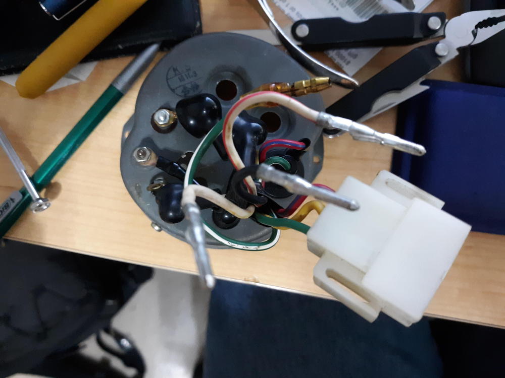
So I was working on a customer's 280Z today, and I managed to isolate/solve a couple of his electrical issues, but there is one with the parking light circuit that I haven't been able figure out quite yet. I had to replace the headlight switch because his old switch had heat damage from the headlight circuit overheating. The pin that operates the rocker would no longer stay in place. I had a spare switch that I needed to re-solder the parking light wires to the switch body. The switch operates normally, but the parking lights won't come on. I checked the resistance of the green/white wire to ground. It was about two ohms even with all of the side marker bulbs out, the right front marker and taillights unplugged. So it only had the license plate light, left front marker and dash lights plugged in. Here is the weird part. I could see the voltage to ground at the switch go to zero. That's what I would expect to see in a circuit with a short. However, the fuse didn't blow. I even monitored with a clamp on ammeter (that was working when I found his "phantom draw" on the battery), but there was no indication of current flow. Yet the voltage always dropped to nothing. The next time he brings his car over, I plan to unplug the connector for the speedometer to try to take the dash lights out of the circuit. I also need to try to unplug the C-8 connector to isolate the dash harness from the body harness. Unfortunately this car has been suffering from long-term benign neglect. It will be an effort to get all of the bugs worked out.
-
Arghhhh Harada Intake Manifold
Interestingly enough most of the photos I could find of the Harada installed on an L series are the ones posted on this site.
-
Arghhhh Harada Intake Manifold
It sounds like you might need some advice from @Mike W or @Zedyone_kenobi
-
Jasper Ga
Let me know where you are interested, and I'll tell you what I know.
-
Jasper Ga
Sorry, Jim. Northwest Arkansas is nice. I have visited the area a couple of times. However, it cannot compete with Road Atlanta, Atlanta Motorsports Park, and Randy's garage. There is just too much good Z stuff in this area.
-
Jasper Ga
The advantage of Dawsonville/Dawson County is that you're in easy driving distance to Road Atlanta and Atlanta Motorsports Park.
-
Jasper Ga
Jasper seems nice. The GZC likes to have lunch at Rocco's Pub when we have drives in that area. One of my GZC friends lives in Waleska. He has restored S30s for people and is really good behind the wheel of a race prepped 240Z, too. Dawsonville/Dawson County is a short drive away from the mountains for fun drives. Shopping choices have been improving there, too, so the boss would be happy. That's not too far from where I live.
-
Weakness Revealed in the GMB and Spectra Mechanic Fuel pumps
It is new. I replaced the original factory fuel pump on another person's car with the Delphi. The car ran well at first but then had some performance issues that indicate a lack of fuel. I replaced the Delphi with another fuel pump I removed from my own car (and was operating fine when removed) a few years ago, looking to see if that was the cause. I have been eliminating one thing after another on that car, and I might actually put the Delphi back on in case the other fuel pump is a contributing issue. At the risk of threadjacking I have already Cut apart a fuel filter to look for debris. It was pristine. Checked the oil in the carburetors (and replaced a piston damper that came apart when the clip at the bottom came off) Adjusted the front float when I discovered there was almost no fuel in the bowl Rebalanced the carburetors. (It was so far out of balance it was only running on the rear carburetor. Don't ask me how it EVER ran well like that.) Now I plan to Look for air leaks around the throttle shafts and intake manifold. Monitor fuel pressure to see if it drops Inspect the banjo filters Disassemble/clean the needle valves Re-install the Delphi pump Not necessarily in that order. So, I figured I would inspect the fuel pump based upon this thread before I re-install.
-
Weakness Revealed in the GMB and Spectra Mechanic Fuel pumps
I took the top off of a Delphi. It is not a confirmed failed pump. It was assembled how you said it should be.
-
Perplexing "FUEL" light malfunction
To make it easier for people to find the bulbs that worked well: https://www.bulbtown.com/1813_Miniature_Bulb_Ba9S_Base_p/1813.htm https://www.bulbtown.com/274020_GM_General_Motors_Replacement_Bulb_p/274020.htm https://www.bulbtown.com/274004_GM_General_Motors_Replacement_Bulb_p/274004.htm
-
Fun post for Tuesday
Ecto-cooler and bacon grease? Oh - how they came together? My breakfast!
-
Weakness Revealed in the GMB and Spectra Mechanic Fuel pumps
Could you take a photo or two and post here? I have one I can take apart.
-
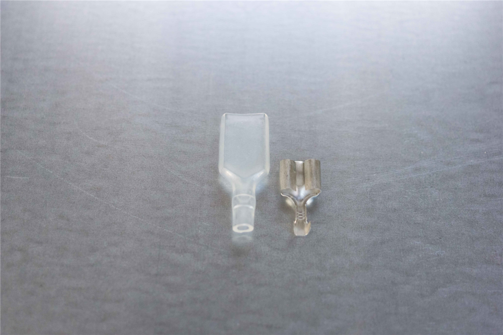
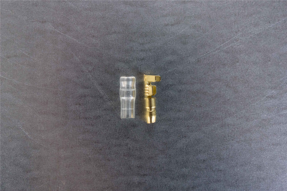
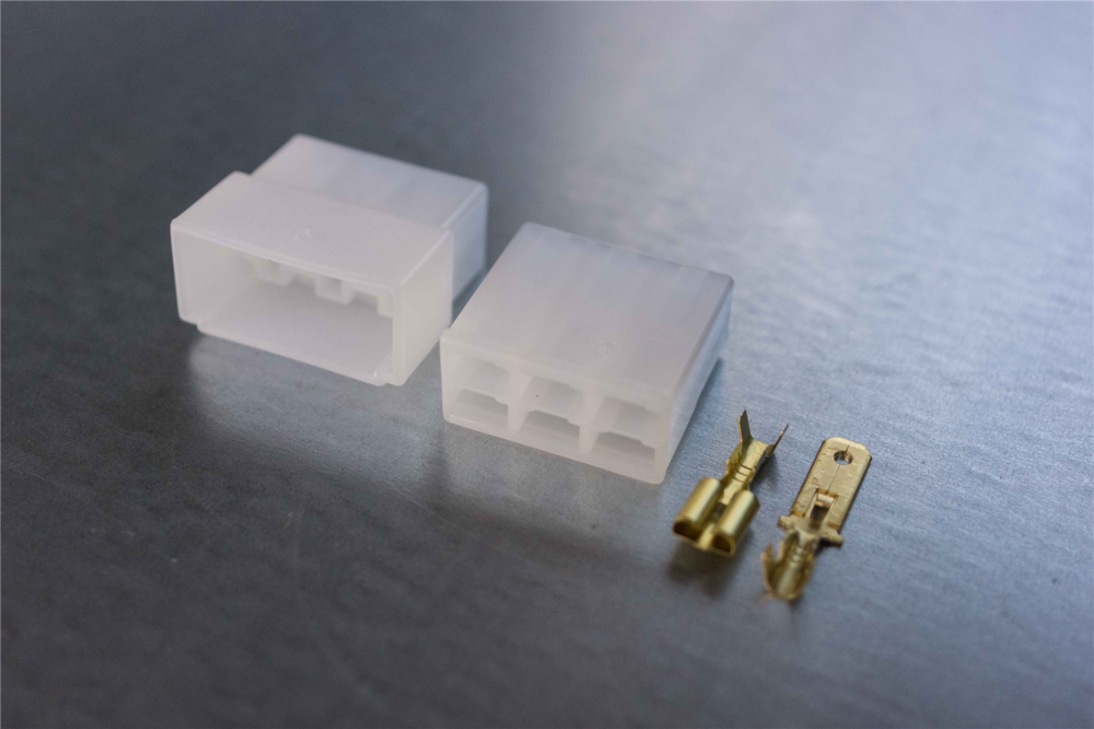
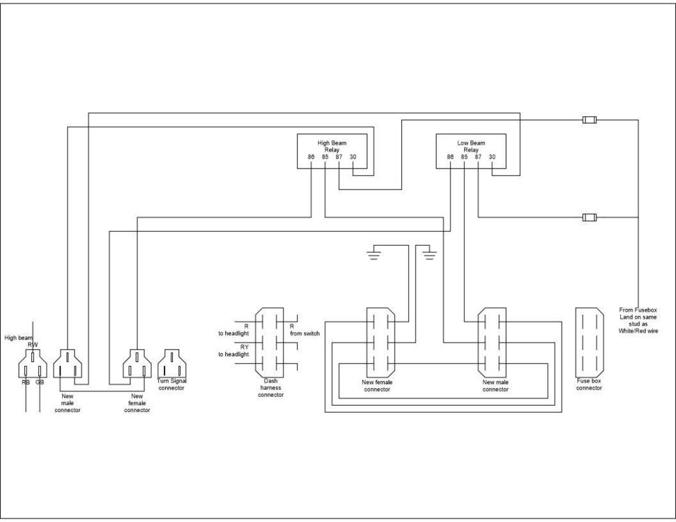
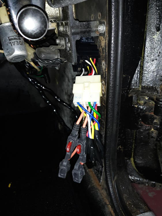
Headlight Relay Modification 240Z
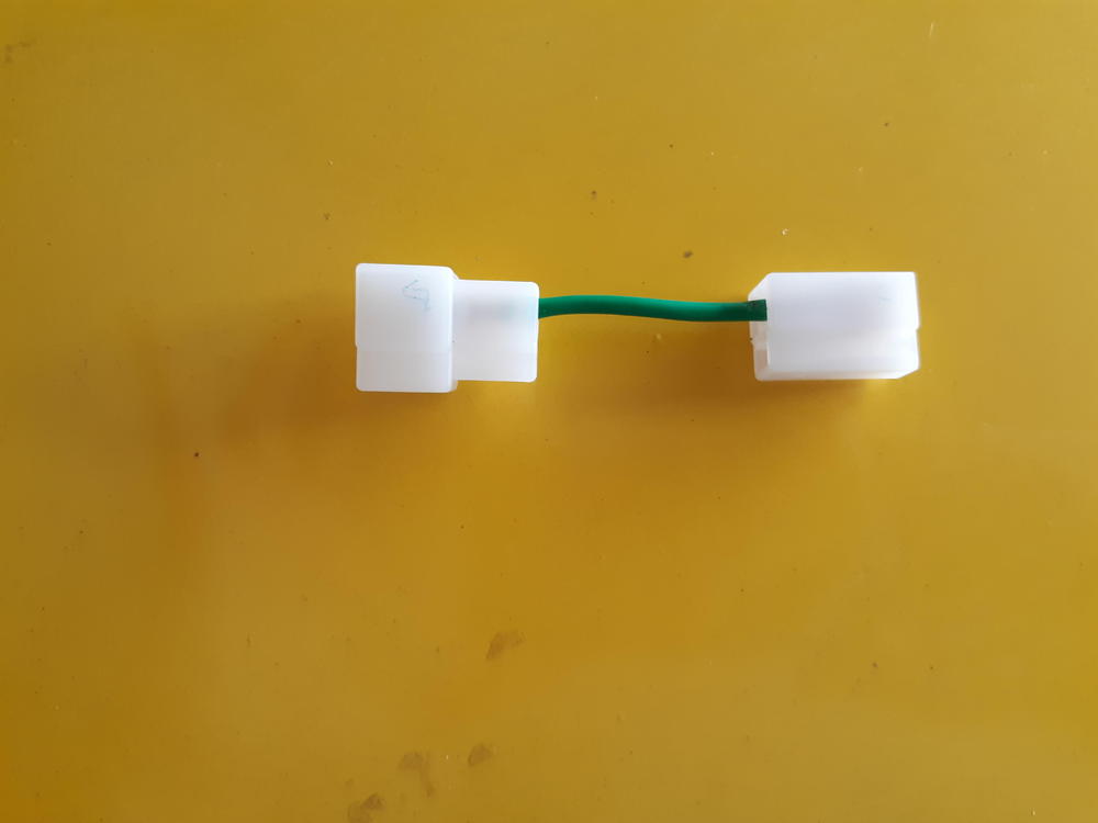
Here is a DIY headlight relay modification that I implemented on a friend's 73 this weekend. This will not work on early Z cars where the headlight switch completed the path to ground. Parts needed: 2 SPDT or SPST automotive relays with bases 14 AWG wire - It is good to have many different colors to keep things straight 12 AWG wire Electrical tape to wrap your wire bundles 1 3-pin 6.3mm non-latching connector (male and female) 1 6-pin 6.3mm non-latching connector (male and female) 2 4mm bullet terminals with insulators and 1 4mm dual socket terminal with insulator 2 inline fuse holders with 10A fuses 2 5A glass fuses 1 yellow ring terminal (solderless lug) (BTW I'm guessing on the size. I can't remember for sure) 2 blue ring terminals (solderless lug) Steps Remove the negative battery cable Remove the clamshell cover on the steering column Remove the center console and loosen the fuse box for access underneath Figure out where you can mount the relays. If you can get relay bases with mounts built in, that is preferred. Estimate the distance from the turn signal connector to the relays and from the fuse box to the relays Cut four lengths of 14 AWG wire for the run from the turn signal connector to the relays and wrap the wires together Cut a short jumper wire to run between the 3-pin male and female connectors per the drawing Note which wire you plan on landing on the connectors Crimp the pins onto the wires and insert them into the connectors Break apart the 3-pin turn signal connector and plug your new connectors into the turn signal connector in the steering column Route the new wire down the steering column and over to where the relays will be mounted. Break apart the 6-pin connector at the fuse box that has 2 red and 1 red/yellow wire. Cut 2 14 AWG wires to run from the fuse box to the relays. Cut two shorter runs of 14 AWG wire (I prefer black) for the grounds. Cut a length of 12 AWG to run from the fuse box to the relays. Cut 4 short 14 AWG jumpers to go between the male and female 6 pin connector. Wrap the 12 AWG with the 2 long 14 AWG wires. Leave enough length of 12 AWG wire to route into position Crimp pins to the wires and insert them into the appropriate connectors. Route the 12 AWG through the underside of the fuse box and attach the yellow ring terminal. Lift the rubber boot covering the terminal on the white/red wire on the underside of the fuse box. Remove the screw, and add the new ring terminal on the screw with the white/red wire. Secure the screw back onto the fuse box and cover with the rubber boot. Secure the fusebox to the car. Connect the jumper harness into the fuse box connectors. Route the ground wires over to a screw. Trim the length of the wires if necessary. Attach the blue ring terminals and secure the ground wires to the car. Route the 3 wire bundle over to the relays. Trim the length of the wires if necessary. Attach the 4mm dual socket terminal to the 12 AWG wire. Attach 1 4 mm bullet terminal to each inline fuseholder. Attach the fuseholders to the 12 AWG wire. You can do one of two things at this point. You can remove the existing wires from the relay bases and use 6.3 mm female terminals on the new wires, or you can use an 8-pin 6.33 non-latching connector to connect the relay bases to the new wires. Make the connections per the attached schematic. Change the headlight fuses in the fuse box to 5A. Attach the negative to battery. Test your headlight relays by turning on the headlight switch and alternating between high beam and low beam. Once you verify relay operation, install 10A fuses in the inline fuseholders. Replace the center console and clamshell. Here is the schematic: This reverses the original design to have 2 positive wires going to the headlights and 1 negative. This allows the use of LED headlights.


