


.JPG.cfcada9cf1c1b502df3f5f2f2ca3ff36.JPG)

SteveJ
Free Member
-
Joined
-
Last visited
Everything posted by SteveJ
-
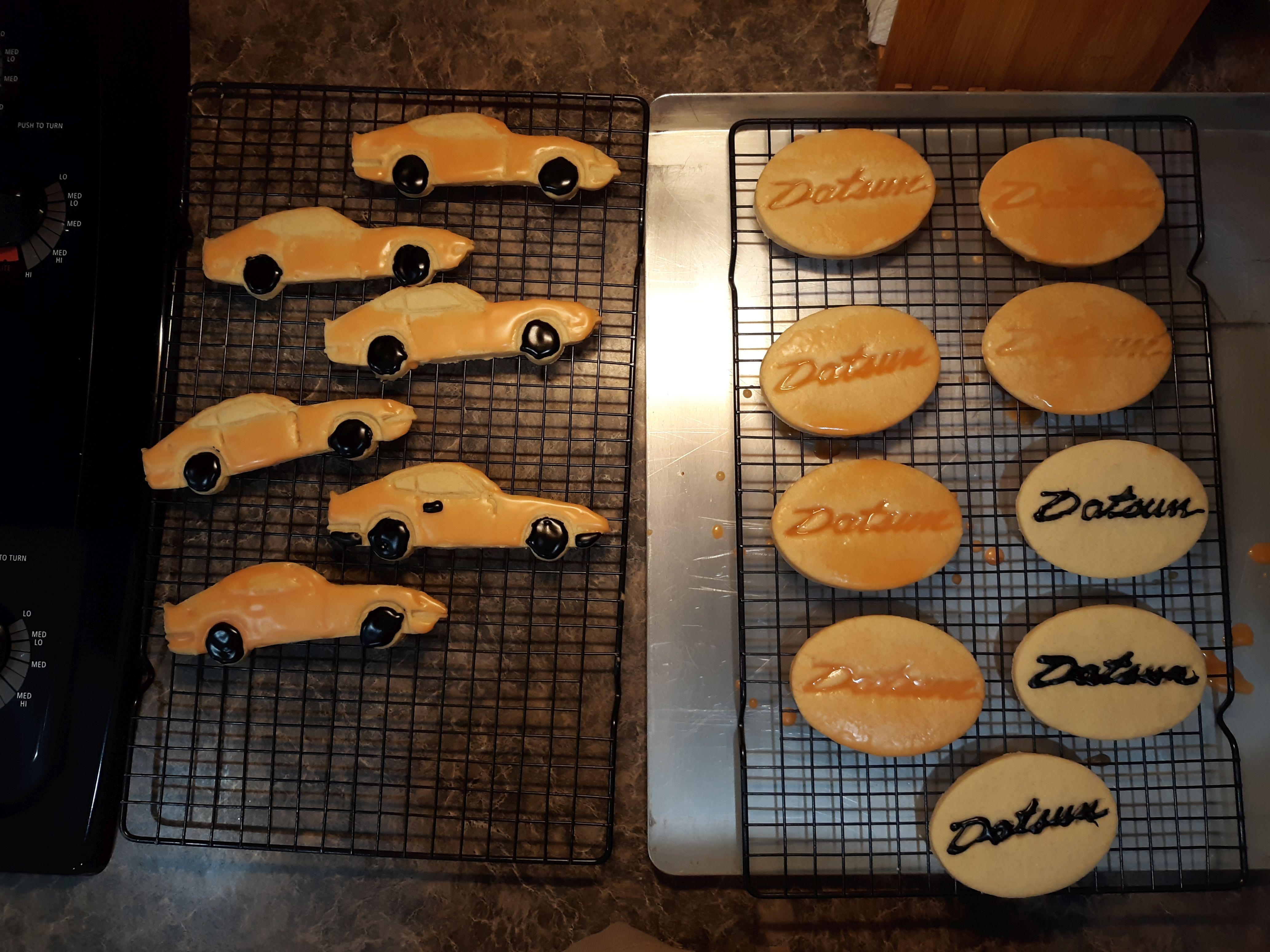
 Working from home and eating sugar cookies.
 -
@jfa.series1 - I think this is pretty close if not the same. After all, both are sold by Rustoleum. https://www.amazon.com/Rust-Oleum-Automotive-260510-12-Ounce-Sandable/dp/B006ZLQ4HQ
-
There are some car related things you can do inside.

-
It's About Time?
-
I did say those things in my first response on this thread. I cannot help it if you are too obtuse to absorb it.
-
The person who started this thread hasn't been back to this site since November 2010 according to his profile.
-
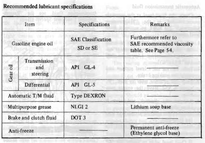
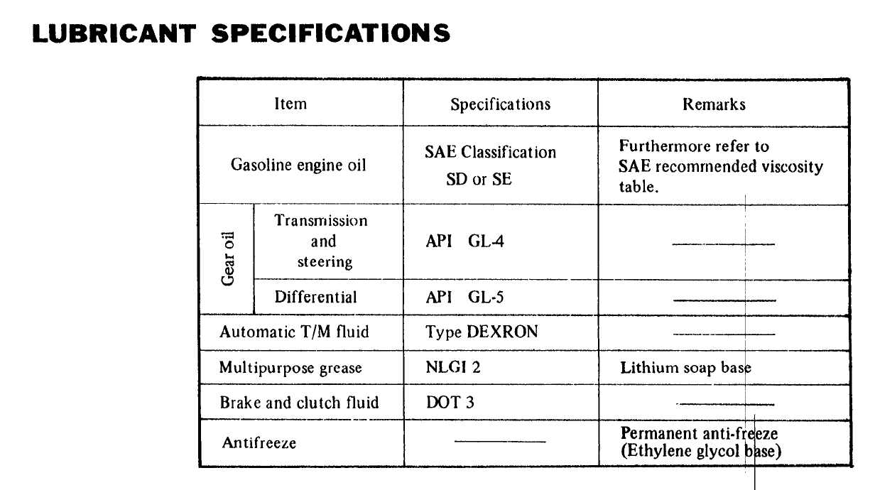
From the factory service manual: From the owner's manual: At least they are consistent. As far as type Dexron: https://www.yotatech.com/forums/f2/dexron-ii-iii-32776/

-
It would go nicely with Dan Banks's fire truck. http://cincyconcours.com/largeimage.asp?txt_image=_DSC2518&txt_year=2011
-
1st - You have series and parallel elements in the way you drew up your circuit. I have spent many years reviewing controls drawings for work, and I have studied the wiring diagrams for S30s for over 25 years. I can recognize a good and bad circuit design. 2nd - The current doesn't disappear. Your circuit is designed wrong. You have the coil in SERIES with the headlight, AND you have the coil in PARALLEL with your path to ground. I read your stuff. You don't understand what you're doing. When I can wire up a circuit per your design and it doesn't work, I think that proves it. You have not shown a workable circuit. If you think you have, wire it up and prove me wrong. Spoiler: You won't prove me wrong. Click here
-
-
-
So I rigged up a test in my garage. Per my suspicions, the relay coil did not pick up when it was in series with the headlight.
-
Controlling the brightness works best by using a PWM. Read the attached for a quick overview. ApplicationNote_SE-AP00040-E.pdf
-
Yes, sir.
-
-
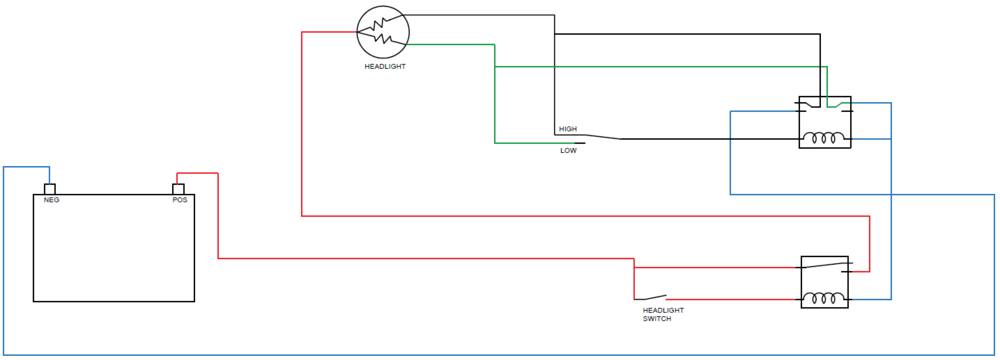
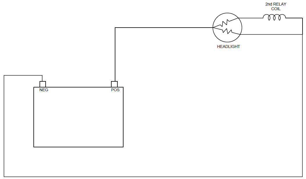
Think of the headlight as two resistors. They are both connected to the battery positive. Since the Normally Closed contact on the second relay is connected to ground, you can see the green and blue connect. That means the low beam circuit has a path to ground until that coil could energize. However, even with the switch in the high beam position, the coil can not energize. So electrically, when you move the high/low beam switch to high beam, this is what the circuit looks like: While the coil in the relay is an inductor, for the purposes of this explanation, we will only look at the resistance (impedance) of the coil. At the headlight, there are two branches to the circuit. One goes through the headlight high beam filament and the relay coil and returns to negative. The other branch goes through the low beam filament and returns to negative. Since we know the voltage of the battery (12 VDC) and the resistance of the components of the circuit (4 ohms for the filament and 80 ohms for the coil), we can calculate the current flowing through each branch and the voltage drop across each component. Total current = Battery voltage divided by Effective resistance R1 = R(headlight) + R(coil) = 4 + 80 = 84 R2 = R(headlight) = 4 Since this site has limited HTML capabilities, here's a link to see how to calculate effective resistance: https://www.electronics-tutorials.ws/resistor/res_4.html R (eff) = 3.82 ohms Total Current = 3.14 A Indeed, when you apply Ohms Law to each branch of the circuit, it matches our results. I1 = V/R1 = 12/84 = 0.14 A I2 = V/R2 = 12/4 = 3.00 A So now we can calculate the voltage drop across each component for the branch with the high beam coil. V (high beam filament) = 0.14 * 4 = 0.57 V V (coil) = 11.43 V Even if that is enough power for the coil to pull in the contacts, you have another problem. When the relay contacts connect the high beam circuit to ground, the voltage at the coil drops to zero. (In the first diagram, the black wire would have 0 VDC to ground with the relay contact closed. It is all the same wire electrically speaking.) When the coil de-energizes due to no voltage, the contacts will return to their normally closed state. Your headlights would switch to low beam. The coil would energize and swap to high beam. The voltage at the coil drops to zero...ad infinitum until you swap the high/low beam switch back to low beam.

-
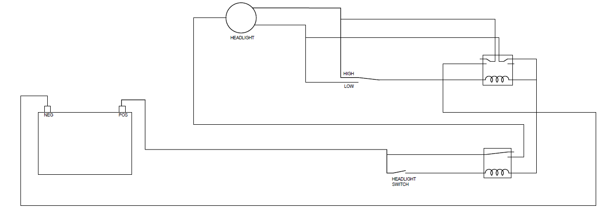
The short answer is that it won't work. The longer answer is that you will never have sufficient current flowing through the second relay coil. You have a parallel path to ground. I've made a simplified drawing of your circuit that I hope allows you to see the issue. If you removed the high/low beam switch from the car and had the headlight switch on, you would find you have 12VDC to ground on both the red/black wire and red/white wire. The headlight would not be shining, and the filament just acts like an ordinary piece of wire. In your drawing, you have the low beam circuit on a normally closed contact. That gives it a straight path to ground. This actually renders your other design flaw moot. The second flaw is that the headlight and second relay coil are in series. The relay coil has a resistance of around 80 ohms. The high beam filament has a resistance of less than 4 ohms. Since they are in series, that means the voltage drop across the coil is going to be at least 20 times more than the voltage drop across the headlight filament. At less than 5% of its designed operating voltage, the headlight would not even have a dim glow. All working examples of headlight relays isolate the positive and negative for the relay coils from the positive and negative for the headlights. Also, it's smarter to have two positive wires and one negative wire for the headlights in case you ever want to use LED headlights.

-
The downside is that my wife has already reported me to HR...twice.
-
To elaborate on what @Patconsaid, if you don't have the coil wire firmly seated against the contact in the distributor cap, you WILL have arcing between the wire and cap. This arcing will heat up a destroy the center post on the cap. I actually got a $700 discount on my 260Z because of this. The owner planned on selling it for $3200 but knocked it down to $2500 because it wouldn't run. With a new cap and new plugs, it ran fine. He still sold it to me for $2500.
-
Pop a huge bowl of popcorn for this one. The audio isn't great, but the subject of the interview is.
-
He's in Madison, WI.
-
I'm glad it worked to your satisfaction, Ron. From the first of my research, I read that the LED color should match the lens color. I might have used some white LEDs in the center gauge pod, though. It's been long enough ago that I can't remember. The bottom line is that you will be able to see at night. I suggest that you replace the 20A fuse in the parking light circuit with a 10A fuse. The wiring wasn't really up to handling 20A, so if you get a short, you could melt wiring (or a connector) with the 20A fuse.
If you retard the timing too much, the engine won't run. You can run the car with the static timing at 30 degrees. It will ping like crazy if you aren't running racing gas...So I've heard from a friend.
While the tach is out, you could use a meter like this one to test the signal going to the tach. https://www.amazon.com/gp/product/B0002LZU7K or https://www.amazon.com/Mrcartool-Digital-Multimeter-500-10000-Temperature/dp/B07VKLKDZL Connect the positive lead to the blue wire and connect the negative to ground. Put the meter on 6 cyl and start the car. If the signal isn't consistent, then you have a different issue to track down. If the signal is good, your tach is going bad.


Important Information
By using this site, you agree to our Privacy Policy and Guidelines. We have placed cookies on your device to help make this website better. You can adjust your cookie settings, otherwise we'll assume you're okay to continue.