.JPG.cfcada9cf1c1b502df3f5f2f2ca3ff36.JPG)

SteveJ
Free Member
-
Joined
-
Last visited
Everything posted by SteveJ
-
 Please go to the top right of your screen where your username is. Click on it, and choose Account Settings. In the left hand column of the screen, you will see Signature. Click on that and add the year of your car to your signature. Without that bit of knowledge, I'm not sure if you're doing a bad job of throwing parts at a problem or a terrible job of throwing parts at a problem. In your voltage testing, you do not say what RPM the car was running when you took your measurements. That makes a difference. Look at the EE section of the factory service manual for your year and read what it says about testing.
 -
Excellent. When diagnosing an electrical issue, you can start at the battery positive and work your way to ground, start at the ground and work your way to battery positive, or start in the middle and work in one direction or another. Since we know the car runs, make sure you set the engine to top dead center before swapping the distributor. Take a photo of the rotor so you are sure how it is oriented. Make sure you have a good ground for the new distributor, too.
-
What parts did you remove from the distributor? Are you sure the TIU isn't getting a signal from the distributor? Did you unplug the TIU? When asking for help, it is good to give specific answers to questions asked. We need to know EXACTLY what you did because we can't see it ourselves. It's the details you leave out that make responses wild guesses instead of clear diagnostics. Let me give you an example. I went to a friend's house to help with an ignition issue on a 260Z. He said the car would start but die when the key went to run. From that, I had a clear idea of where to start looking for the problem. However, the car would not start when I was at his house. I tried to diagnose the issue, but I was stumped about the sudden lack of spark. My diagnostics suggested I look at the TIU, but it was not in the passenger footwell. Eventually it came out that the son had removed the aftermarket AC, and the TIU had been re-mounted by a previous owner onto the mounting bracket for the evaporator. The son did not think it was an important detail that he had been removing parts from the car. After we re-installed the TIU, I was able to confirm my diagnosis, and they had a running 260Z. The Crane 3000 was an improvement over the points based system in my 240Z, but that is a completely different setup from yours. Most of the improvement was due to the fact that I suck at setting points. I don't need a Crane ignition on my 260Z since a previous owner did the ZX distributor/ignition swap into the car, and that ignition works fine, so I cannot comment on performance differences. I cannot tell what the issue is with for sure your tachometer because you didn't answer my questions in my previous post.
-
The 260Z already has an electronic ignition, so that will limit your gains right there. Having used a Crane 3000 on a 240Z in the past (like over 20 years ago...), I recall the instructions talking about removing the points, etc. What modifications did you do to the 260Z distributor since it does not have points? Did you unplug the transistor ignition unit (TIU)? For the 260Z and 280Z, the reluctor in the distributor triggers the TIU. The TIU completes the path to ground that causes the energy stored in the coil to be released to cause a spark. This circuit for grounding is monitored by the tachometer for the pulse needed to indicate the RPM of the engine. In order to get the tachometer to function properly, you would have to modify the wiring so the wire that the tach uses to monitor the TIU is monitoring the ground leg of the Crane.
-
The fact that you have voltage at the coil eliminates the tachometer swap as a problem. Did the voltage fluctuate when cranking the engine. If it stayed at 9VDC, then you're still missing the path to ground for the spark to happen. Either the points are not closing, or the circuit from the negative of the coil to ground (that goes through the points) is compromised.
-
First things first. Have you verified whether or not you have voltage at the coil as I described for you to test?
-
There appears to be a significant disconnect between what I described and what you did. For resistance, you should start with the lowest setting. That would be 200Ω and not 2MΩ. This is important. In my previous post, I said I measured 78.7Ω across the coil. That would be 0.0000787MΩ, or on your display, 0.00MΩ. This is important. If the coil was shorted out, the resistance would be much less than 78.7Ω, but your meter would still give you the same reading as a good coil if you use the 2MΩ scale. As for the test that you said failed, what were you using for your 12VDC source? Did you hear a click in the relay (possibly 2 clicks)? Try this test: Put the positive from the 12VDC source on pin 95. Connect the negative to pins 94 and 96. Put your meter on the 200Ω setting and measure resistance across 91 and 97. Here is the theory of operation for that relay: If there is voltage across pins 95 and 94, the coil is energized, and the the contact near pin 96 closes. Now there should be voltage across pins 95 and 96, and the second coil is energized. That causes the relay to move the switch that connects 91 and 95 so that it now connects 91 and 97. This is all relatively binary. Either the circuit is open or closed. Either the coil is energized, or it is not. If there is a voltage drop, it could be from the contact between 91 and 97 getting pitted or dirty so that there is not good contact. This would act like a resistor in the circuit. If the car runs, the relay works. However, the fuel pressure should not be at 48 PSI. I think you're barking up the wrong tree.
-
Now it looks as though you may have a 78 280Z. The PITA is that the wiring diagram doesn't have the pins numbered. There is some numbering on EF-26, so I will use that. Pins 73 & 74 are a coil. You should have some resistance. I don't have the spec for that coil handy, but I measured a couple of standard automotive relays. The coil on one relay measured about 83.6Ω, and the other was 78.7Ω Pins 90 and 91 also are for a coil. There should be resistance. Pins 94 to 95 I believe are for another coil. Again, you should have resistance. Pins 91 to 95 are for a normally closed contact. With the relay unplugged, you should have continuity (nearly 0Ω resistance) across those pins. Search through the old posts on this site. I know I have talked about these relays in the past. Oh, and clean your old connectors. Many people swear by Caig Deoxit.
-
That is exactly the reason for the test I described. In this case, I chose a location in the middle of the circuit. If the first part of the test fails, the problem is between the key and coil. If the second part fails, the problem is between the coil and ground.
-
So with the key in the on position, you should see somewhere around 9VDC from the coil negative to ground. Did you check the gap in the points? This is where an old-fashioned tach/dwell meter can come in handy. If you have voltage from coil negative to ground and no signal on the tach, you know that either the points aren't closing or that the ground for the points is bad/missing.
-
First, what model Z do you have? Is it a North American, European, or JDM model? Here is a general test. If you have a digital voltmeter, put the positive lead on the negative terminal of the coil and the negative lead to ground. With the key on, it should read 9 to 12 volts. Have someone try to start the car while you are watching the voltmeter. If the voltage does not fluctuate significantly, you lost your trigger for spark. I'm not sure what distributor you have or what ignition source you have for your test right now.
-
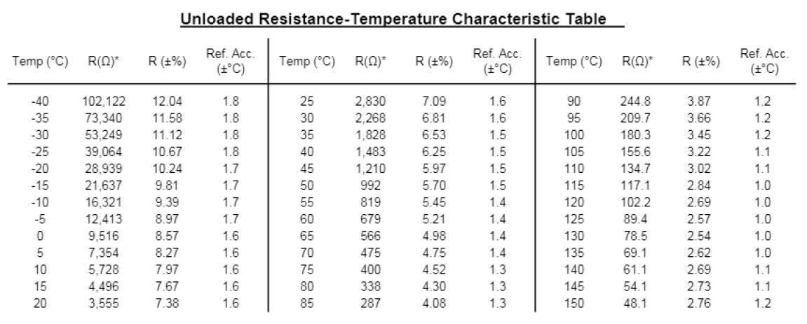
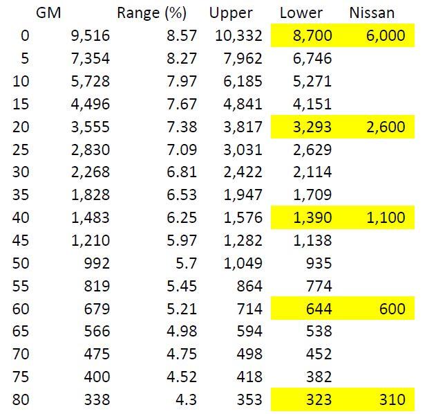
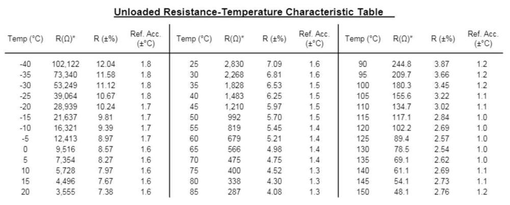
I took a closer look at the approximate values on the FSM chart and compared them to the GM data. The CHTS appears to run a little lower through the operating range (0 deg C to 80 deg C) than the GM sensor. However, a better evaluation would be to run the engine with the CHTS and monitor the resistance while taking temperature readings at the thermostat housing. If the CHTS resistance is too low through that range, I know it could be the source of problems with the fuel injection. The nice thing is that I can test on the car before I get the kit. The challenge with the GM coolant temperature sensor is to make sure it is immersed while using the adapter. Whatever the result, I get to learn something...and maybe the lessons learned will benefit our community.
-
First, let's go over terminology. This is important for clear communications. Voltmeter - Measures voltage (difference in potential) across a source or a load, such as across the terminals of a battery. Ammeter - Measures current flow through wires. Ohmmeter - Measures the resistance (opposition to current flow) of a load. VOM - Volt Ohm Meter: This is a meter designed to measure voltage or resistance Multimeter - A meter that at a minimum measures voltage, resistance, and current. Some multimeters can measure frequency or inductance, and others have functionality to test transistors. Autoranging - A VOM or multimeter that will automatically select the range for the display, going up or down orders of magnitude. Continuity - Continuous, as in a continuous piece of wire. Now let's talk about resistance. Wire has resistance. Connections have resistance. Both should be low enough that we can ignore it if things are in good working order. Even a VOM or multimeter has resistance. An air gap has very high resistance. If you are using a digital VOM/multimeter with autoranging, the first thing you do is set the meter to measure resistance. The display will typically show OL (open line), and there will probably be a capital M near the reading to show megaohms. Touch your leads together. The display should go down to less than 1, and the M should disappear. If the meter has a continuity buzzer, it should be buzzing at this time. Please note that the threshold for a continuity buzzer may be several ohms. The autoranging feature will change the display, possibly without you realizing it. It can go from megaohms, to kiloohms, and to ohms virtually instantly, so you have to watch for the M or K on the display. If you have to set the range manually on your VOM, start with the LOWEST range when you are checking for continuity. Touch the leads together and make sure the reading goes down to less than 1. If you are using a higher range, the display may read less than 1, but you could have a lot of resistance. My philosophy when checking continuity is to IGNORE THE CONTINUITY BUZZER. The value on the display is important. So go back and start over. Have a notepad with you to record readings. Also, where exactly are you placing the probes for the meter? Be specific so we can tell whether or not your technique is correct. Finally, what year Z do you have? There are differences, and if you need help, we need to know which FSM to refer to. Feel free to post a photo of your meter so we can verify what setting to use on the dial.
-
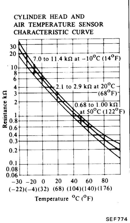
One of the important things to integrate into the fuel injection ECU is the coolant temperature sensor. Since the 260Z doesn't have one, I need to figure out how to incorporate this sensor. Use a 280Z coolant temperature sensor in the port occupied by the temperature switch. (The consensus is that it won't fit.) Use a 3/8 BSPT male to 3/8 NPT female adapter to put the sensor in the port occupied by the temperature switch. (I got the adapter. It doesn't look like it will fit.) Use a 1/2 BSPT male to 3/8 NPT female adapter to put the sensor in the port that is currently plugged. (This still seems viable.) Take advantage of the CHTS port in the Maxima N47 head and use the Nissan CHTS in lieu of the coolant temperature sensor. In order to do number 4, I have to know whether the sensors have similar resistance curves. The 82 FSM EFEC section provided me the CHTS curve. Based upon a measurement I took today, I think the middle curve is the one I need to focus on. And a little searching on the interwebs gave me a data sheet on the GM coolant temperature sensor. Unless I am misinterpreting the FSM curve and the table, I believe I can use the CHTS for the temperature sensor data for the ECU.
-
And the genuine article from Courtesy Nissan: https://www.courtesyparts.com/oem-parts/nissan-rivet-plastic-black-90909e4100 And Nissan Parts Deal: https://www.nissanpartsdeal.com/parts/nissan-rivet-plastic~90909-e4100.html Tasca: https://www.tascaparts.com/oem-parts/nissan-rivet-plastic-black-90909e4100
-
So this got me looking on ebay. I found some panel rivet kits that have rivets in a similar size to the Z rivets. https://www.ebay.com/itm/690Pcs-Car-Auto-Push-Pin-Rivet-Trim-Fastener-Clip-Panel-Body-Interior-Assortment/254096165616?hash=item3b294fcaf0:g:bREAAOSwh99cSstW:rk:2:pf:0 https://www.ebay.com/itm/690pcs-Car-Automotive-Push-Pins-Rivet-Trim-Clip-Panel-Body-Kits-Assortment/173657019916?epid=21026357388&hash=item286ec3d60c:g:0AAAAOSw6jJb-LiG:rk:3:pf:0 It looks like the Nissan part is designed for a 5mm hole, while the Ford (and many others on the market) appear to be designed for a 1/4 inch hole. And to make a correction, it looks like the BMW rivet is likely the correct width. Depth may still be an issue. Let us know if they work.
-
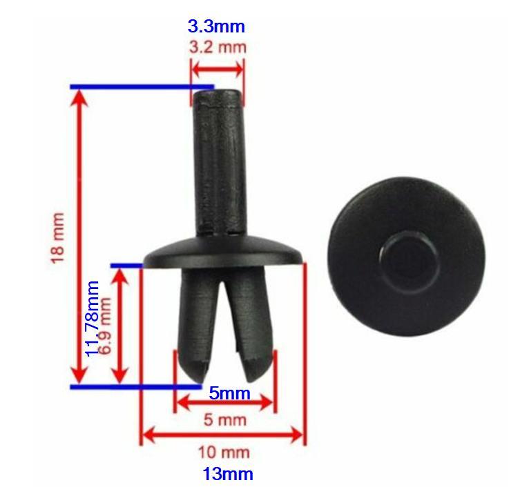
I measured what I believe to be a genuine Nissan panel rivet to compare to the measurements of the BMW part. The BMW part seems to be a little smaller. Those rivets may have issues with staying firmly in the anchor points. The measurements for the Nissan part numbers are in blue.
-
https://www.ebay.com/itm/50-FORD-FENDER-SHIELD-PUSH-TYPE-RETAINERS-OEM-387843-S/253285631459?epid=1189303991&hash=item3af90005e3:g:zaEAAMXQlrxRa9Hi:rk:4:pf:0
-
I miss going to that show.
-
Thanks for the offer, Bruce. I have the fitting on order. I'm trying to line up all the support parts I may need so I don't have as much down time on the Z. I even have the 3 screw carburetors sitting in my garage, waiting for the conversion. I sent the check a month ago for the fuel injection kit. It won't be shipped for about another month. I'm guessing a lot of British sports car fans want a winter project, too.
-
It could be a bad distributor cap, too. When I was buying the 260Z, the guy was knocking $700 off the price since it wouldn't run. It turned out that it was just a bad distributor cap. I put on a new cap and got the car running.
-
I should add that I also bought a CHTS to play with since I have the N47 Maxima head. I'll find out if the 280ZX CHTS fits.
-
Thank you for taking the time to educate me, Bruce. I did find what I hope to be the proper adapter: http://www.britishmetrics.com/shop/Brass-Reducing-Bush-BSP/reducing-bush-1-2-bspt-x-3-8-npt.html
-
Here is how a relay works. https://fiddlingwithzcars.wordpress.com/2012/12/22/relays-simplified/ If you don't understand the wiring enough to make your own, I can make a plug & play double socket relay for your car for $50. It won't look the same as stock, but it will work, and if one of the relays fails down the line, you can replace it inexpensively.
-
No problem. It was easy since you were good enough to post a photo that had your fuel rail in it. I didn't even need to do a search. The source and return will be even more obvious when you see how your fuel pump is connected. The return on the fuel rail has a small orifice that acts similar to a fuel pressure regulator (as pointed out elsewhere by @Captain Obvious).