


.JPG.cfcada9cf1c1b502df3f5f2f2ca3ff36.JPG)

SteveJ
Free Member
-
Joined
-
Last visited
Everything posted by SteveJ
-
 Why not modify if the parts aren't in pristine condition? I put 240Z bumpers on the car. I added relays for the headlights and LED headlights. I replaced the engine with a 2.8L that was freshly rebuilt. The previous owner modified the ignition to the ZX ignition. I put on 16 inch wheels. I won't hesitate to modify it some more as I see fit. I'm going to enjoy the car, and my widow can sell it when I'm done enjoying it. As for the seatbelt interlock relay, the requirement went away quickly and quietly toward the end of 1974. Since the 260Z ended up being an extended model year, I believe Nissan was able to get rid of the interlock relay by the time the 280Z was rolled out.
 -
We 260Z owners are in the same boat. Let's row harder.
-
Where did you read about the T connector? Context is everything. Many people have modified their Z cars. One popular conversion is the "one wire GM alternator". You would need to provide a part number/markings on the alternator to confirm. The wires you have circled are the Sense and Lamp wires. The Sense wire tells the alternator what the voltage is in the system. While the Lamp wire compares the output of the alternator to the system voltage. If the output is low, the lamp lights.
-
I just went downstairs to check mine. It has a slight angle down, but it's not that noticeable. I'm not sure whether the angle decreased since that photo on my blog, or if the angle in the photo looks greater because the front end is slightly elevated.
-
Look here. I have one photo after I mounted the air dam and before I mounted the bumper. https://fiddlingwithzcars.wordpress.com/260z-air-dam-and-front-bumper/ I think the top angled back like yours.
-
http://www.classiczcars.com/store/category/6-club-products/
-
The $23,500 is the minimum starting bid. There are no bids, yet.
-
Yeah, I don't think that is a $1500 car, even if it is a 2+2.
-
But who said you had to buy it new? By the time you add your labor in for your square tube idea, you've about paid for that offset wrench anyway.
-
Here's an interesting tool, too. https://www.amazon.com/dp/B00I6TBQIW
-
Okay, the 2 inch 8 point is too big for the gland nut. Too tired to take a photo.
-
2 inches across on the flats...at least for the KYB struts.
-
The 260Z is seen as a transition car in the US while Nissan was finalizing the fuel injection for emissions purposes. On the other hand, with the lack of love, there is less guilt about modifying it.
-
You might need to weld the bolts on to have them secure enough to torque on them. Take photos, too. I want to see if it works.
-
Hmm, thinking about it, you could probably drill a couple of 5 or 6 mm holes in the gland nut and weld them in place. then you could heat the strut tube with a map gas torch and apply brake fluid to help break the rust loose. With the bolts welded in place, you could use them with the tongue and groove pliers to twist off the gland nut.
-
Here is what the redneck in me would do if I was in your situation again, Guy: 1. Weld two 6mm bolts to a piece of steel with a cutout to go around the shaft of the strut. 2. Mark where the bolts strike the top of the gland nut and drill two holes in the gland nut. 3. Apply a lot of brake fluid along the threads. 4. Heat the strut tube with a map gas torch. 5. While hot, apply more brake fluid along the threads. 6. Use the redneck wrench. Of course, when I tackle the 240Z, I'm going to try Jim's socket trick after applying brake fluid to the threads on the struts for several days in advance.
-
Come on down here. I have one.
-
Can you not get an air chisel on one of those cuts to turn it?
-
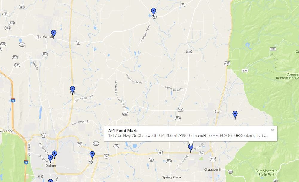
By the way, Jai, there appears to be ethanol free gas in Chatsworth, too, if you trust that station.
-
Jim, I think that might be a deeper well version of the one I purchased. I'll post photos after receipt.
-
You may have misunderstood previous posts. What I have seen posted is that you don't drain the transmission until you can verify that you can open the fill plug. Many people have said it is difficult to impossible to get some of them off. The only time I tried, I got it off with no problem, possibly because I read some good advice here before attempting to do it.
-
Exposed? Bow Chicka WOW WOW!
-
Get it right, man! It's Bow Chicka WOW WOW!
-
Unfortunately, I once had a gland nut get boogered by tongue & groove pliers.
-
I took a chance on a used 8 point on ebay. I will report back the results.

