.JPG.cfcada9cf1c1b502df3f5f2f2ca3ff36.JPG)

SteveJ
Free Member
-
Joined
-
Last visited
Everything posted by SteveJ
-
 If your electrical skills are lacking, it could be a challenge. You could also contact Dave, aka Zs-ondabrain. He has designed a plug & play for the 240Z. I think he has also made a few for 280Zs. Given the choice between the two, I'd pay extra for Dave's if I were you. You will receive better instructions and support.
 -
Keep in mind that coolant in the exhaust will give a sweet smell.
-
Arne said If you look at the link I posted, you will see the circuit has 2 (two) 12 VDC+ wires and a common ground. If you look at the wiring diagram for your car (or the images I posted), you will see 1 (one) 12VDC+ wire and two wires that could go to ground. You select your path to ground with the high/low beam switch. I understand perfectly well what is going on. I offered to draw up the relay circuit for you. I can't help it that you don't understand. Just buy the relay kit in the Black Dragon catalog. If you figure out how to wire it in, it will fix your problem. There is a way to fix your problem without installing relays, but it involves re-wiring your switch. I wouldn't recommend going down that path.
-
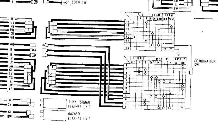
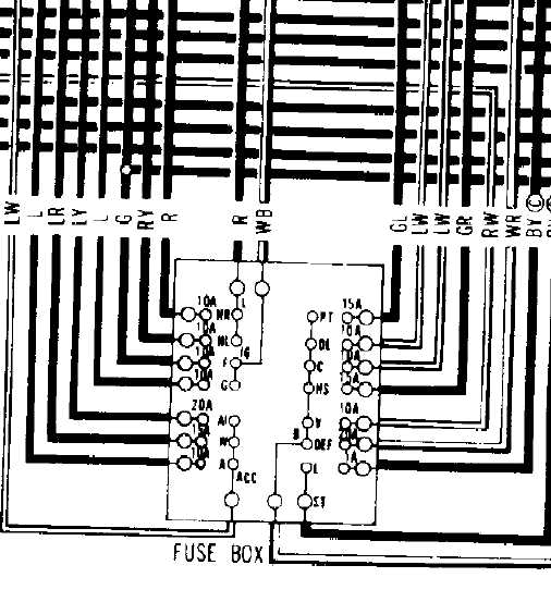
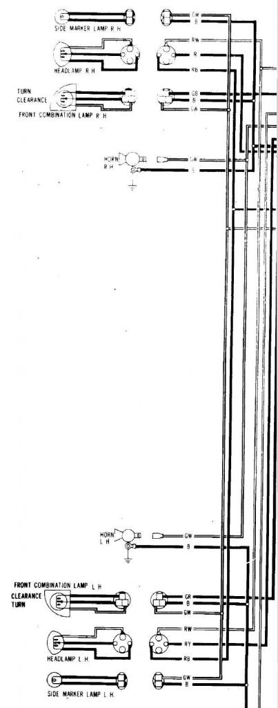
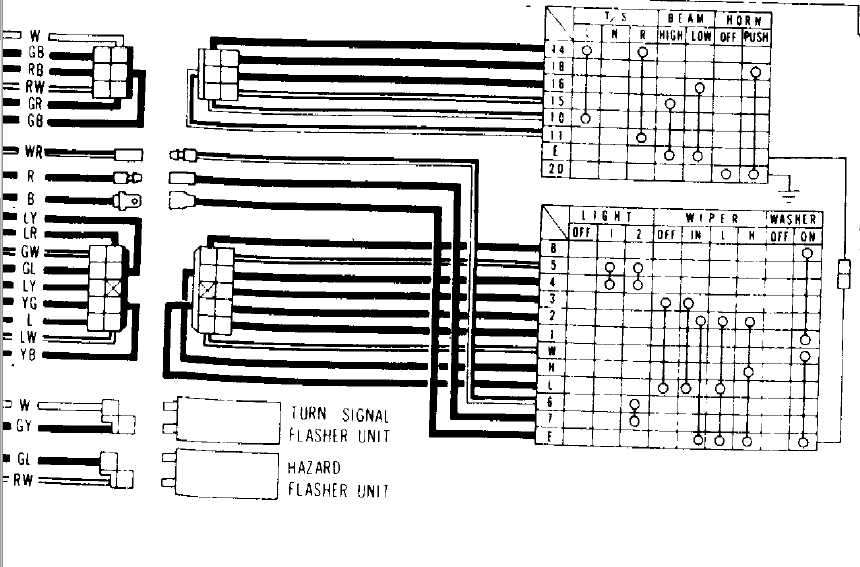
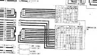
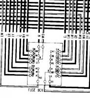
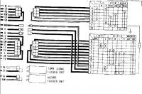
I have studied the wiring diagrams from many of the FSMs' date=' especially after others pointed out to me that the 70 & 71 240Zs have their headlight circuits wired differently than other S30s. I have converted both of my cars to relays for headlight controls. I do know what I'm talking about, and yes, I am an electrical engineer. I'll step you through the circuit, using a positive to negative convention. 1. 12VDC+ comes into the combo switch on the right using a White/Red wire. 2. When the headlight switch is in position 2, it completes the contact and goes out the Red wire. (See the first attachment.) 3. The red wire goes into the fusebox and goes through two fuses. The fuse for the right headlight has a Red wire. The fuse for the left headlight has a Red/Yellow wire. (See the second attachment.) 4. The Red and Red/Yellow wires travel to their respective headlights and land on the common pin for the headlights. Two wires come out of each headlight. One wire is Red/Black. The other wire is Red/White. The two Red/Black wires join as do the two Red/White wires. (See the third attachment.) The wires then go back to the combo switch on the turn stalk. 5. If the switch is in the low beam setting, the Red/Black wire will be connected to ground via the Black wire. If the switch is in the high beam setting, the Red/White wire will be connected to ground via the Black wire. (See the first attachment.) At no time does the polarity change. The path to ground changes. Since the D in LED stands for diode, yes, polarity is important. Did the headlights come with instructions? Look for any guidance on wiring. My guess is that the common pin is supposed to be grounded, as I said before. If you still don't believe me, take the voltage readings at the headlights again. However, take out BOTH headlights. With the switch in low beams, you will find that you have 12VDC (probably less) between two of the three pins. When you change it to high beams, the pin that was positive before will still be positive. The negative will go to the third pin.

-
Have you tried sending a PM to Dave, aka Zs-ondabrain? You apparently miswired something.
-
Switching polarity? Nope. They don't. The stock wiring on the 280Z has the 12VDC going to both headlights. The return wires go to the high/low beam switch. That switch selects the path to ground. Look at the circuit that Daniel Stern uses to demonstrate the value of relays. Note that the ground is common and you have two 12VDC sources coming in. If your LED headlights require a common ground, you could put in relays that utilize a common ground. If you don't understand what I'm saying, let me know, and I'll draw up the circuit for you.
-
aj, Did you look at your plugs? What did they look like?
-
Well, the ZX distributor's module is mounted on the distributor. I'm not sure if the 280Z had that. Don't they have a separate box? For the 240Z & 260Z, it does away with points. Also there were a lot of 79-81 ZXs made, so parts are plentiful.
-
I replaced the boot on the firewall for the throttle today. I also detached the speedometer cable from the speedometer to replace it. I noticed a wire going through the grommet for the speedometer cable, so I traced it. One end went to the positive side of the coil. I followed it under the drivers seat and up the back and under the carpet on the rear deck. It continued over to the passenger side taillight where it was poorly jury-rigged to the fuel pump. The wire was nice and brittle for the full length and poorly spliced in a couple of places. After I replace the speedometer cable, I'm going to look at the fuel pump relays to make sure they work.
-
Yes, the ZX distributor swap has been done to many cars. My 260Z has it, and I'm going to do it to the 240Z.
-
-
If you search this site, someone posted quite a few links within the last year for Z suppliers.
-
With some studying of the wiring diagram, that could be figured out. For instance let's look at the switch. From the attached image we can determine the following connections at the different switch positions: Off LY - YB In LY - YB YG - WR (12VDC) Low WR - YB WR - YG High WR - LY WR - YB Tracing those wires will probably take us over to the amplifier circuit. From seeing what connects where and the other diagram in the BE section, we can probably figure out the function.
-
So he was using a relay with 2 form A contacts?
-
It's not like there were a lot of options for the North American market. Don't take this the wrong way, but you're on a fishing trip. Tell us what you're trying to catch, and we can tell you if it's worth the effort or where to find the fish. In other words, your question is a little on the vague side. Are you trying to find info to have a period correct restoration or what?
-
No. The VIN does not have that info.
-
Check the BE section of the FSM.
-
Phil, would you post a link to the site where you found that if you remember where it came from? Edit: From what I could find, the FL series of fusible links are for modern fusible links.
-
I'm not the most mechanically inclined. (Translation: I manage to fix more than I break.) I dropped the tank in the 73 enough to replace a bunch of old hoses. It wasn't that painful.
-
-
I think I saw them for $263 + $8.50 S&H each on Amazon.
-
If you haven't already done so, I suggest that you also incorporate relays into the design. Getting 12VDC to the headlights help, even for LEDs.
-
They are definitely to reduce heat transfer to the carburetors. It's bad enough that they have to sit over the exhaust manifold. Why have them get heated up from the intake manifold, too?
-
Yeah, that's right. It's 4 gauges. I remember reading that, too. I was thinking 2 when I was typing because you usually don't see the odd number wire gauges. Thanks for catching that, Phil.
-
We had a good discussion on fusible links just a couple of days ago. Anyway, the gauge of the wire in the circuit gives a good rule of thumb for the ampacity of a fuse to protect it. Though the 0.03 mm fusible link would translate into about a 20 AWG wire & fusible links tend to be 2 gauges smaller than the wires they protect, I get a feeling that the wires in the circuit are probably around a 14 AWG. You don't want to pump more than about 30 Amps through those wires and only for a very short time. If the gauge of the wire in the circuit is actually larger (I don't have a 280Z.), then my guess would be that there is a component that needs the protection. As for why it would be different from factory...sometimes factory engineers get things wrong. Also, sometimes standards are revised due to lessons from experience.