.JPG.cfcada9cf1c1b502df3f5f2f2ca3ff36.JPG)

SteveJ
Free Member
-
Joined
-
Last visited
Everything posted by SteveJ
-
 You may be able to get away with 2 of them as long as two wheels will turn. I have too much stuff in my garage for them to be useful, and the contraction lines on my driveway are too big even for the wheels on those dollies.
 -
If you have a flat floor, these work well to move the car around: https://www.harborfreight.com/1300-lb-capacity-self-loading-positioning-wheel-dolly-64601.html
-
I'm guessing those are pictures from an iPhone. Apple has to do things "better" even it if is incompatible with most everybody else's platform. Sometimes it pushes the state of the art forward, and sometimes it just sticks out like a sore thumb.
-
Meh, it's just one of those senior moments we all have from time-to-time, like all of the times I couldn't get the car to start because I failed to put the wire back on the coil.
-
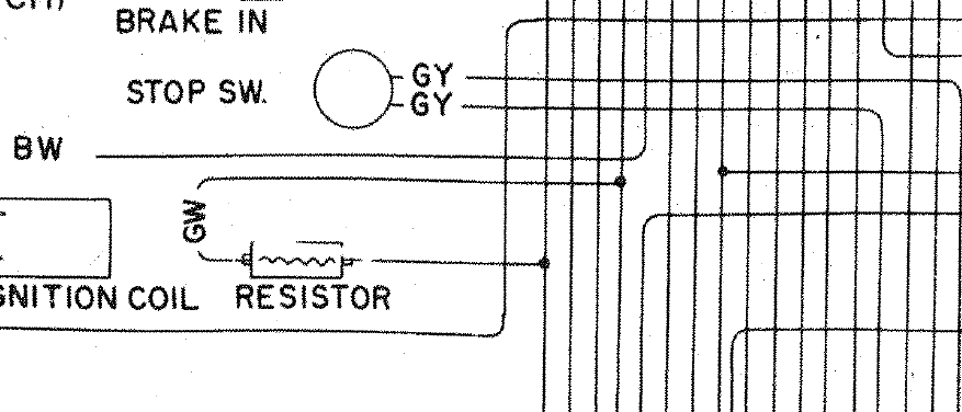
That's the ballast resistor. So conventional wisdom says the 4 wire tach won't work well with the ZX ignition. I didn't have the ZX ignition in my 240Z long enough to confirm it. I have the Pertronix with no ballast resistor and no issues with the tachometer. If you wire the car with fidelity to the FSM wiring diagram, you would need to do the following to go with conventional wisdom: Swap 280Z tach internals into the 240Z tach. Jumper the black/white and green/white wires at tach connection in the dash harness. Run a wire from coil negative to the tachometer and have a 2.2k Ohm 1/2 watt resistor between the coil and the tachometer.
-
You could take the plugs out, dry them, and turn the engine over without plugs in to make sure you don't have too much fuel in the cylinders. You should really verify that the cam is getting oiled before you run the car, though.
-
I'm not. I'm suggesting oil pressure gauges.
-
This gauge might work better: https://www.amazon.com/CWB00060-Liquid-Filled-Pressure-Gauge/dp/B00TYY8L2M
-
Okay, it doesn't need to be 10AWG. It doesn't carry that much current, especially if you go to an LED headlight.
-
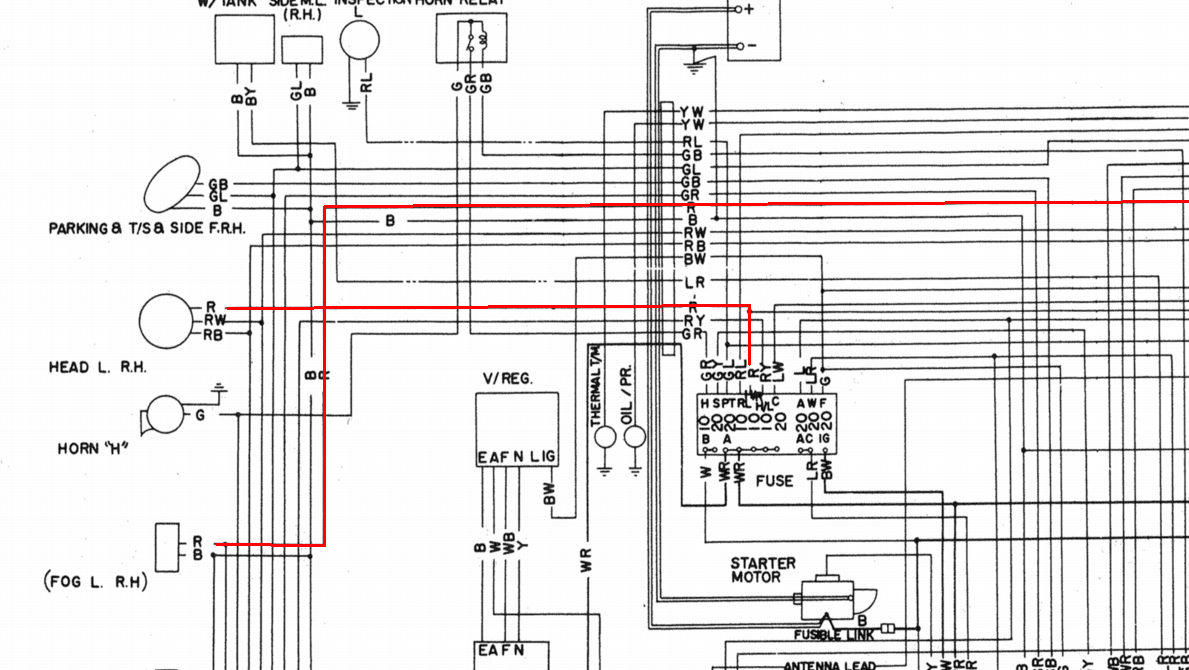
I'm not sure we're at the same place here. If you are talking about in the engine harness, I can see in the FSM, it shows a red for the headlights and a red for the fog lights. I do not know if the fog lights were run as 10AWG. The headlights were 14 AWG. My earlier statement on the red being 10AWG going to the fuse box is incorrect about the 71. I was thinking about the 72 & 73.

-
I can't say for sure. I would have to build a female connector to test. 10 AWG goes from the switch to the fuse box, then goes to both headlight fuses. (That statement is wrong for the 70 & 71. The headlight switch in those years completed the path to ground.) The red for the right headlight should be 14 AWG. When I replaced the clutch MC in the 73, it was not sealed. It was also not original having been replaced in 94. The FSM doesn't say anything about sealing it, either. Maybe @zspert could confirm.
-
You are correct on the colors. red/white and red/black are high and low beam returns. Red is the right headlight, and red/yellow is left. I did find this for the engine harness side: https://www.240zrubberparts.com/apps/webstore/products/show/5507024 As far as the connectors go, the VC 3 pin is different from stock. http://www.vintageconnections.com/Products/Detail/80 This is what the stock female side looks like (on the headlight harness itself): The VC connector might not light up quite right with this.
-
Yeah, the buzzer doesn't affect anything else.
-
I've never taken the dash apart enough to find the bastard, so I'm not sure what it looks like. I just know that mine would work randomly.
-
I do believe that is part of key in ignition buzzer.
-
Here's a thread that talks about the anti-backfire valve:
-
The steering lock switch is where you put the ignition key into. There have been threads about some newer switches lacking the wiring for the key in buzzer.
-
One of the connections on the driver door switch I think is for the key in ignition buzzer. (Mine works at random intervals.) One of the wires goes across to the passenger side to complete the path to ground for the door light when passenger door is open.
-
Try reaching out to Z Therapy to see if that's a part they stock. I think it's part ZT154. https://ztherapy.com/products/masterprices/master_price_list.htm It looks like 72 nozzles are rare to unobtanium on the open market. MSA has 4 screw nozzles. Someone more knowledgeable than I am will have to advise more.
-
Yep, the headlight harness connections have been hacked off. *Sigh*
-
You lost me on that one. Is there a picture I should be looking at?
-
So in examining the 73 & 74 switch diagrams, the blue/yellow goes to switch position 3 on both. I'll look on the 73 dash harness to see where it goes at the intermittent relay, but I may need to be reminded.
-
Fair enough. We were all there at one time. Consider joining the Desert Z Association (http://www.desertzassociation.com/) and ask if someone could help you or recommend a shop. Another alternative is that maybe a member on here could help you or you could pay him to work on your car.
-
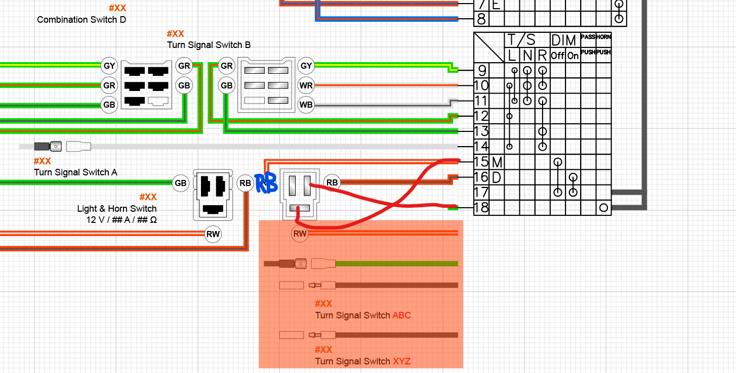
The turn signal switch changed between 73 and 74 when Nissan switched to separate bulbs for the brake lights and turn signals. The GB on #18 and the RB should go like this: See the diagram above. The RB and RW wires have to meet up with each other on the 3 pin connector. The third wire is for the horn. Wires from 3, 17, and 18 are all grounded. I don't have a photo available to show this. (That also goes to question 2.) It should be a single black wire from the turn signal switch to the headlight switch side. The white wire going to pin #14 on the switch is the power for the turn signals downstream from the turn signal flasher. Yes, the wires are reversed between the wiring harness and the switch. The yellow/blue wire from the 74 wiper controls goes to a yellow/blue in the 74 dash harness and over to the intermittent relay.

-
What is the timing at idle and at 3,000 RPM? Have you checked the valve lash?