.JPG.cfcada9cf1c1b502df3f5f2f2ca3ff36.JPG)

SteveJ
Community Member
-
Joined
-
Last visited
Everything posted by SteveJ
-
So does your car still have the automatic transmission? The black wire that joins a red/black is only for an automatic. With the Pertronix, neither of those wires needs to be landed to an ignition component. As I stated before, the black wire from the Pertronix needs to be on coil negative. The red wire from the Pertronix and the black/white (from the tachometer) should be on coil positive. Where you have the jumper between the green/white and black/white wires, make sure there is no chance either side can touch the fender. It could short the ignition to ground. Did you follow the directions in the video I linked to make sure your wiring is right?
-
Maybe reach out to Z Car Garage to see if they might have one. I'll see if the one I have lying around is in decent shape.
-
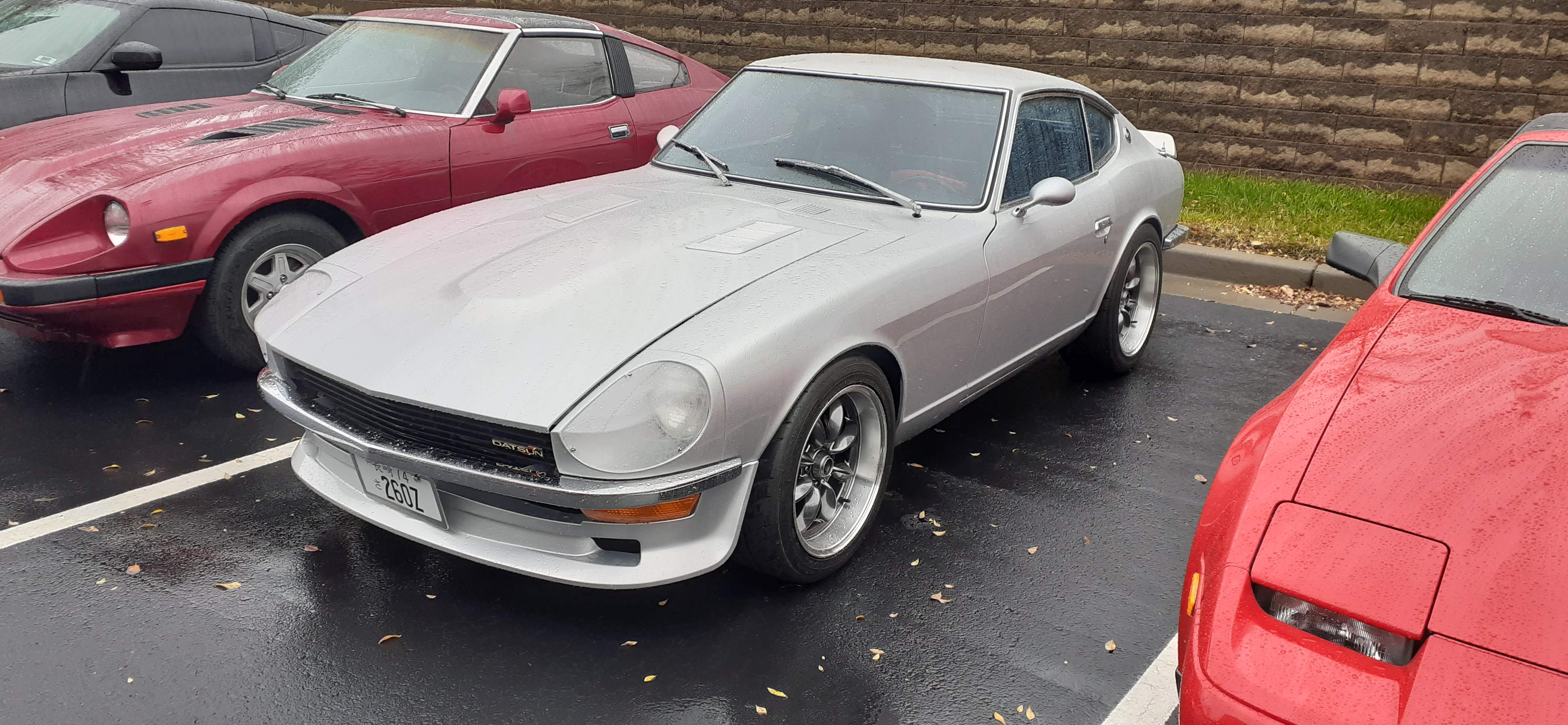
Gateway Classic Cars invited the Georgia Z Club to be the featured club at one of their monthly meets, Caffeine and Chrome. We ended up in the December slot which was nice because it's also the holiday party for Gateway Classic Cars and their Toys for Tots collection. Despite some rain, we had around 28 cars total show up. The funny thing is that the regular crowd stayed home because of the rain, so it became an ad hoc GZC holiday party with Gateway supplying the food. We managed to fill three boxes with toys, too. Here's a link to an album with photos of most of the cars that showed up today: https://photos.app.goo.gl/CLAHn9vzgg3PxeqSA


-
I'm not sure what wire you're talking about. Photos help a lot!
-
First, here's how to make sure which black/white wire is which. Make sure you have the green/white and both black/white wires disconnected for this test. When you have identified which black/white goes to the coil, make sure it and the red wire of the Pertronix are both mounted to coil positive. The black wire from the Pertronix should be on coil negative. Make sure the other black/white is firmly connected to the green/white. Check resistance between the distributor body and the car body. It should be <1 Ohm. Then if the car doesn't start, you'll need to find a helper. Measure voltage to ground at coil positive while trying to start. It should be between 10 and 12 volts. Measure voltage to ground at coil negative while trying to start. It should fluctuate a lot if the Pertronix is functioning properly. If the car doesn't start, take clear photos of the wiring around the ballast resistor and coil. Also make sure you haven't pull the coil wire out some from either the coil or the distributor.

-
You nailed it. It could be a dirty contacts, or the nubbin in the switch has worn down/melted. @jfa.series1 has some good pics in this thread: Here's a thread where we got carried away talking about the nubbins:
-
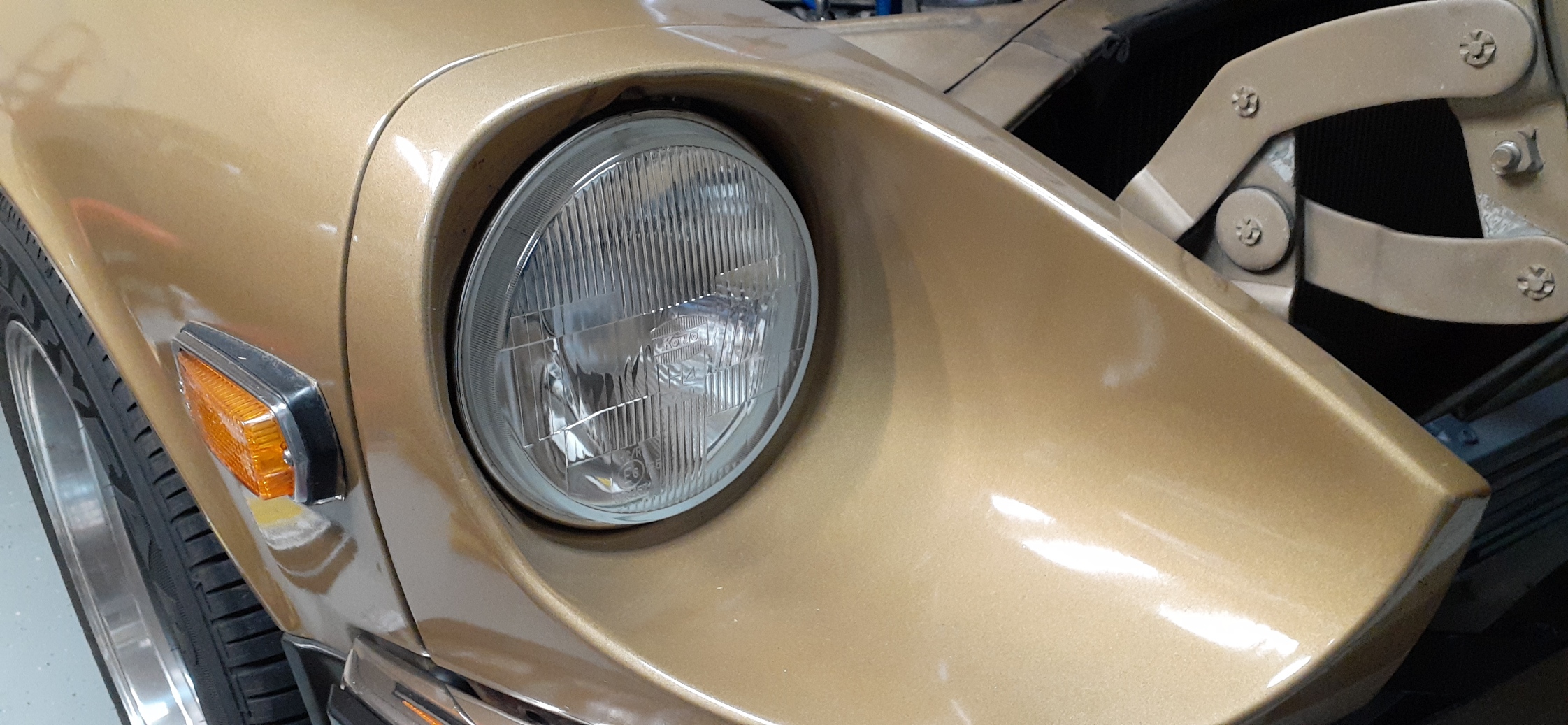
They are essentially plug and play. You will need to back out the screws on the retaining ring a fair amount to get everything lined up right for reassembly.
-
I installed the Koito H4 housings with Auxito H4 LED bulbs in my 260Z a couple of days ago. I had been using the Auxito bulbs with a set of H4 housings I picked up from Black Dragon many years ago, but I didn't like the appearance.

-
This may help some. https://www.hagerty.com/media/advice/shipping-a-car-heres-how-and-why-to-make-the-right-choice/ https://www.hagerty.com/assets/PDF/DomesticShipping.pdf https://www.hagerty.com/resources/how-tos/10-car-shipping-and-transportation-tips
-
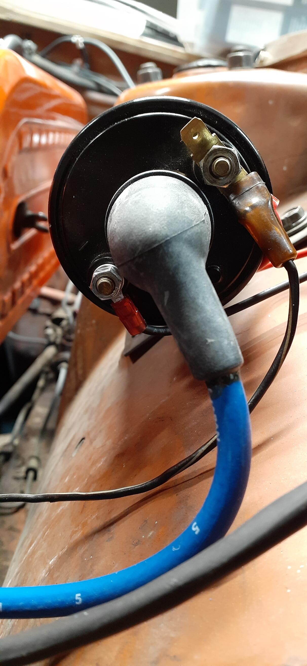
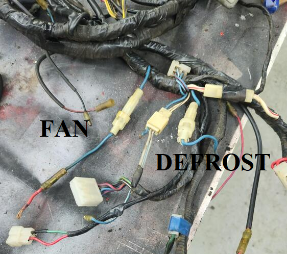
It's hard to tell with the hacking that was done to that harness, but this is my guess.
-
Clean the wires and tell us the wire colors, too.
-
What are the wire colors?
-
It isn't adjustable. That's not uncommon for aftermarket VRs. If the VR is malfunctioning, the battery sense wire (white in the engine harness) could be feeding the field wire (white/black) that goes to the alternator. On an aftermarket 260Z VR that I have handy, the white/black is connected to a wire wound resistor. If it has voltage all of the time, that could be a current draw. Plug the VR back in. (Listen for a click in the VR, too.) Unplug the two wire connector from the back of the alternator, and check for voltage to ground on the white/black wire on that connector.
-
For the 260Z, the relays and pump were from the factory.
-
So the main power is hooked up right. Your chart shows that isn't a problem. And the green/blue wire has 12VDC on the 9 pin connector. That is perfect. You said you found one cross connect in the center stack. When you turn the combo switch to turn on the running lights now, the gauge lights should come on. Does that happen after you corrected the one cross connect? If not, with the switch in the position to turn on the parking lights, check voltage to ground on the green/blue and green/white wires where they are soldered to the switch. If the gauge lights still only come on with the key in ON, pull the ignition fuse and see if the lights are still on. If so, repeat for the AC fuse and wiper fuse.
-
Disconnect the 9-pin connector on the steering column and take photos of it, especially where the pins are. If the 9 pin connector is disconnected, you won't ever have a complete circuit for the parking lights/gauges. Take the cover off the fuse box, and take a clear photo of the fuse box. Also, did you check for voltage at the parking light fuse (the one I marked as #2 above)? What are the results? The fuse should have voltage to ground on both sides even with the key off. In order to do the diagnostics properly, we have to go through the circuit carefully. Since there is not an engine in the car, could you share a picture of how you have the positive battery terminal connected to the wiring harness? Normally, the positive terminal is connected to the starter, and a fusible link is attached to the same terminal on the starter, going to the white wire.
-
Well, new does not always mean good anymore. If you're using a clamp ammeter, can you measure the draw at each of the wires on the VR? Also, open up the VR to see if it's mechanical or solid state. If it's mechanical, it may be adjustable.
-
Ironically, if you look in the EF section of the FSM, you'll find that the power to the fuel pump is cut during cranking. You don't say what carburetors you are using, but there should be enough fuel in the float bowls for starting.
-
Yeah, you need to disconnect the battery negative before you play with the fuse box. On the other hand, cleaning the fuse box may have removed the blockage that was preventing the light from coming on.
-
It was for the helper electric fuel pump. If you don't want it, I'll buy it from you for $40+shipping. If you're going to use an electric fuel pump, then keep it.
-
With the fusible links in Disconnect the voltage regulator and measure current. If you still see the drain, disconnect the alternator and re-measure. I am thinking that pulling either fusible link breaks the connection between the battery and alternator.
-
So did you remove the bulb and measure resistance across it or do some other test to verify you have a good bulb? With a bad bulb, you would still see voltage across the bulb. You didn't mention anything about measuring current. Also what is the resistance between the negative side of the dome light and chassis ground? How about between battery positive and the positive of the dome light? (Of course, those measurements are with the bulb out.) Was the bulb in your photo the bulb you used, or was there any chance you used an LED bulb? There is one other factor that would allow you to see voltage, but the circuit may not work. That would be corrosion, such as around the door switch. Think of it this way: Your battery is like a water tower. It's full and ready to supply water. You can verify this by using a pressure gauge (voltmeter). The pipes are all connected, and you open the valve (close the switch). However, you don't see much water coming out (no light). What you didn't realize was that the pipes are old, and a lot of calcium had built up, blocking the pipe (corrosion). If you had a flow meter installed (ammeter), you could measure the low flow. The resistance tests I asked about above are also like testing the pipes, though with the meter, you can get a false low resistance reading. Good voltage does not equal good current flow.
-
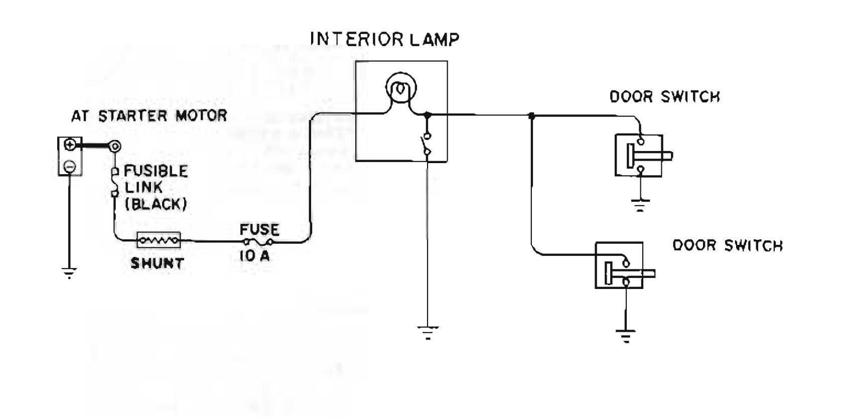
Have you looked at how the circuit is designed? Here it is from the 74 FSM, but all S30s are the same for the dome lamp. Measuring voltage at the light does not mean it will light up. It means it will light up once you give the circuit a path to ground. Corrosion on the body around the door switches can prevent the path to ground as the door switch grounds at the body.

-
I'm thinking you wiggled a connection somewhere, and there may be an intermittent connection. What did you do (touch) between the readings at the fusebox when you had no voltage and when you had voltage?
-
Did you test the fuse box with the ignition off? Those circuits should have voltage when the car isn't running.