.JPG.cfcada9cf1c1b502df3f5f2f2ca3ff36.JPG)

SteveJ
Free Member
-
Joined
-
Last visited
Everything posted by SteveJ
-
 You don't need the diodes. What I gave you was a very simple way to wire. You said you aren't using the GW wire for the tach, so all you would need to do is land the GW and BW wire at the same place in the engine bay or replace the terminals on them now for a male/female bullet. Why do you want to do 10 times more work?
 -
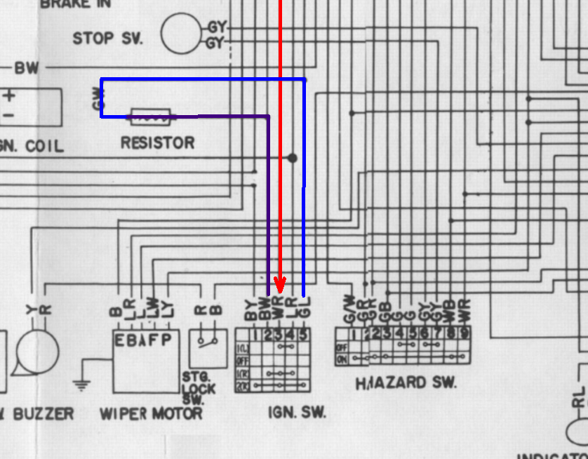
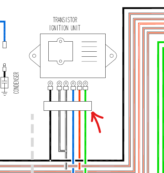
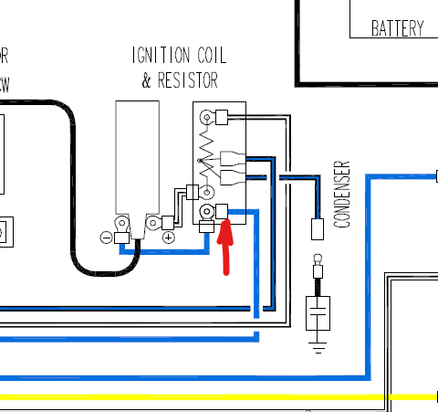
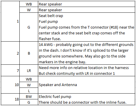
In the stock wiring, the GW wire has power with the key in Start and goes over to the tachometer. This wire also branches over to the ballast resistor. The BW wire branches out to the engine bay to the other side of the ballast resistor. The other branch of the BW wire goes to the center stack where it splits again. One branch goes to the fuse box and the other goes to a 2 pin T-shaped connector. You could get a connector from Vintage Connections that will let you plug an inline fuse into the circuit and go out to the pink wire on the Haltech. http://www.vintageconnections.com/Products/Detail/79 You could also get a single pin connector to attach the inline fuse to the pink wire: http://www.vintageconnections.com/Products/Detail/78 The only caveat is that you can't have the GW wire going to the tachometer connector anymore.
-
Probably the easiest way to ensure you have power at start and on is to jumper the BW from the ignition switch to the GW at the ballast resistor. You won't backfeed the circuit for the starter solenoid. After watching Duffy's video, I ran a test on my 73. I disconnected the solenoid wire and took apart the connection for the BW and GW wires under the hood that I did put together to jumper out the ballast. (BW cannot backfeed the GW wire.) I put the turn signal into a right turn and put the key in start. The turn signal flashed, meaning in my 73 with an original switch (AFAIK) supplies power to the BW wire in start and on.
-
I used a clip lead and remote starter. https://www.amazon.com/INNOVA-3630-Remote-Starter-Switch/dp/B000EVU8MK Clip one end of the clip lead to the negative of the battery and the other to the body of the horn. Clip one end of the remote starter to the positive of the battery and the other end to the terminal on the horn. I suggest holding the horn so the positive terminal cannot touch the body of the car and short. Press the button on the remote starter.
-
And I have already demonstrated that your flawed design won't work and should be consigned to the trash heap. But what would I know? I only work with these kinds of circuits for a living.
-
You may want to check out Vintage Dashes or search for Hung Vu on Facebook. https://www.classiczcars.com/forums/topic/67730-reproduction-240-dash/#comment-643729
-
It's not exactly plug and play. I just don't like cutting factory wires if I don't have to. One could back out the BW wires out of C-2 and C-3 and put them into smaller AMP connectors. The dash harness side would go to the key source on the Pertronix. The BW on the engine harness side would go to the BW on the Pertronix. That would save running a wire all of the way from the Pertronix in the passenger footwell to the coil.
-
D'oh, Mouser doesn't expect to get any of the 172508-1 until mid December.

-
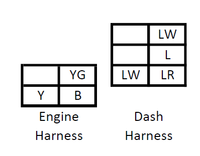
If I'm correct, these are the same style connectors as C-2 and C-3, though photos of those taken apart would be helpful to confirm.
-
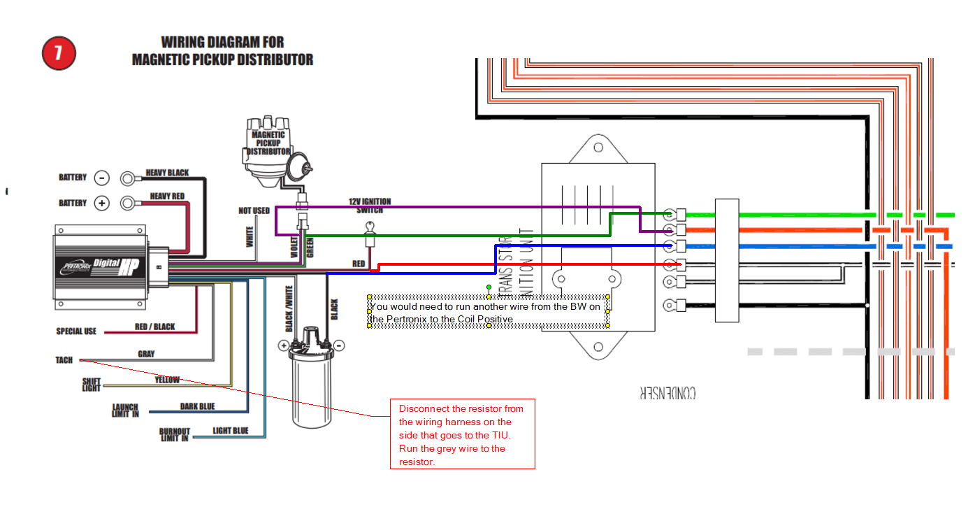
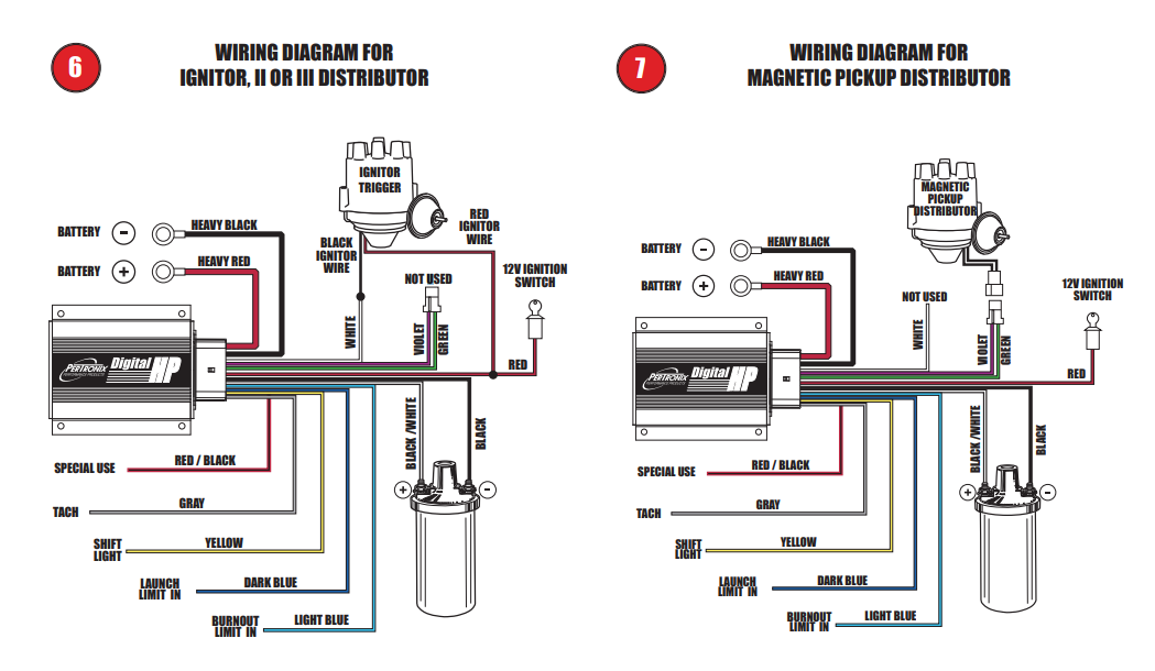
I'm thinking this is right, but I'm open to critiques. This is how I would see it going for the wiring. You would need to make sure you lift the wire between the ballast resistor and coil positive. Could this be done without running a single wire out to the coil? sure, but that would require more wire modifications between the dash harness and engine harness. Edit: Yes, it could be done without running the wire out to the coil, but it would require buying 2 sets of connectors to make jumper harnesses between C-2 and C-3 to intercept the BW wire at those junctions.

-
Agreed. I'm going to write up my suggestions.
-
Looking at the wiring diagrams: For the 280Z, I would think the grey wire would connect to the blue wire that goes back to the TIU and tach.

-
A friend of mine has been running the FAST system for a while. He has driven his Z to California and back at least a couple of times with it.
-
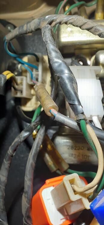
Found it Here are wires going to the intermittent relay: Obviously, the wiring diagram in the FSM isn't quite right for the intermittent relay as it shows 9 wires. There isn't a BY wire going to the relay, and there is only one ground wire.
-
Perfect. Now I can look for it in my car.
-
It is an interesting mystery. The wiring diagram was probably done well after the parts were designed, so it's not surprising. Humans were involved, and they didn't have the neat CAD software available to fix their mistakes quickly. Just today I noticed an anomaly in the wiring diagram for the intermittent relay in the 73. I would need to hook up my oscilloscope to see if the transfer is truly bumpless between start and on for the IG terminal on the switch. I don't think it is, but with the inertia of the engine once it fires, it could handle the very short gap in time.
-
So for #7, the LR wire coming off the fuse box goes in several directions. It turns into BY and goes out to the washer It goes to the Intermittent Relay for the wipers as LR It turns into R and goes out to the reverse switch (and inhibitor switch on the automatic). There is another LR wire that goes from the defroster switch to the defroster relay. I think there is a mistake on the wiring diagram for the intermittent relay. It shows the LR wire from the fuse box turning into BY when it gets to the intermittent relay, and another LR wire on the intermittent relay that goes to the wiper motor as BY. My guess is that BY and LR are swapped on the intermittent relay. Can you post a photo of #7 with a little more context in the wire bundle? That may help narrow it down.
-
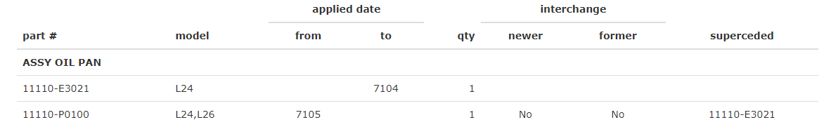
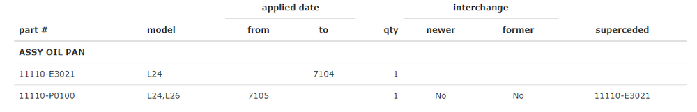
I'm not an expert, but it looks like an early pan.
-
This may help you with identification
-
I don't think there is a need to measure the voltage fluctuation. That is how those meters operate. I forgot to include an example. Here's a video I did of a fuel gauge operating. You can see the current fluctuating on the power supply. That is from the gauge operating.
-
The fluctuation of the test light is right in line with the operation of the oil pressure metering circuit. If you measured voltage to ground where you put the test light, you would see fluctuating voltage. It would be easier for you to read the ohmmeter at the 200 ohm setting, but it appears as though the sender is working. It was disconnected from the wire from the gauge, wasn't it?
-
Thanks for the verification. At 15.7, the charging system is running high. Is that how it has been running, or have you changed out the alternator or voltage regulator? By the way, did you ever check the sending unit for resistance?
-
I'm thinking that if you replaced the electrical component, the replacement may have design changes from the original. Unfortunately it's a part that sees a lot of use over the lifespan of the car, so finding a completely original switch on an early car could be a challenge. This really doesn't go to solve Duffy's issue. It's really just to validate the wiring drawings, so I should make a separate thread for this rabbit hole.
-
Even if it just drops the air temp in the cabin to the mid 80s, that would be a BIG improvement for me.
-