.JPG.cfcada9cf1c1b502df3f5f2f2ca3ff36.JPG)

SteveJ
Free Member
-
Joined
-
Last visited
Everything posted by SteveJ
-
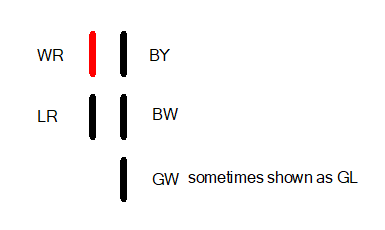
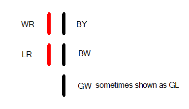
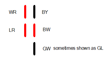
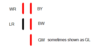
 As designed by Nissan, the BW wire from the ignition switch is not the primary source for power to the coil while cranking. The GW (or GL depending upon the drawing) wire is. The reason is that the GW gives a hotter spark while starting, but in normal operation, the BW wire runs through the ballast resistor to drop the voltage to reduce the wear on the points.
 -
I don't disagree with you except to say it's not a small point. I would say it's a moderately sized point. It would be great if someone with an earlier car could confirm how the "single screw" switch operates electrically. It's pretty easy, as I mentioned before. Take the BY off the solenoid, switch the turn signal switch to left or right, and put the key in start. If the turn signals flash, the BW wire is powered during start. @jfa.series1 Does your car have an original switch?
-
That's not a lot of weight if you live in the Southeastern US. You should have seen me after driving to Memphis and back for ZCON 2015. I would not have minded and extra 70 lbs at all for that trip.
-
Was 15.7 measured with a multimeter or read from the gauge in the car? This is why I like those cigarette lighter voltmeters. They are usually pretty close to a multimeter, and you can see the voltmeter and tachometer at the same time.
-
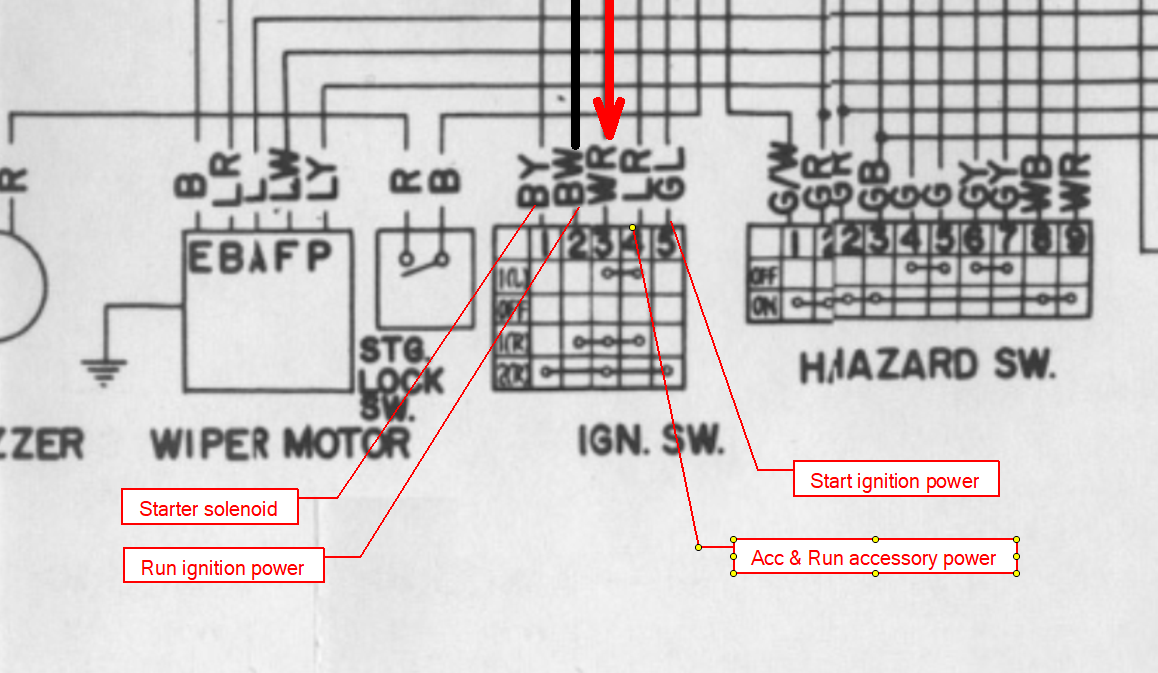
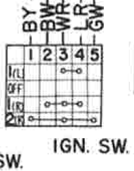
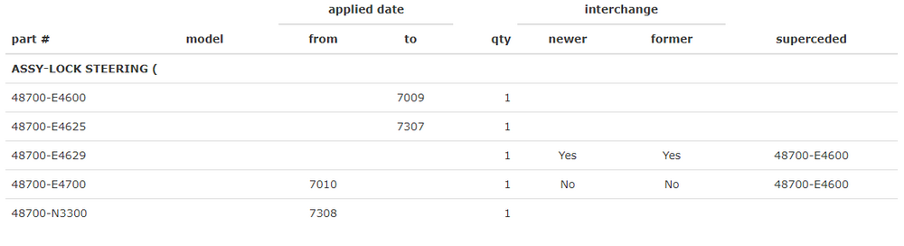
I remember seeing the post of the ignition switch wiring diagrams through the years. It's easy enough to verify on my 73. I just have to lift the solenoid wire off and have the turn signals on. If I have turn signals blinking while starting, then it has power while cranking. The 70 FSM indicates it is not powered during start. The wiring diagram in the 71 supplement shows the same, and the 71 Body and Chassis Part 2 PDF matches. The parts manual also indicates there were separate designs originally. I still have a new D8700-E4629 (in Beck Arnley packaging) that according to Courtesy Parts's website "Replaces: 48700-E4600, 48700-E4625, 48700-E4629" I did a continuity test on that switch and here are the results: (Red indicates continuity with the WR wire, and black indicates no continuity.) OFF Acc On Start So the BW is hot on that switch in start. Either D8700-E4629 is not faithful to the original design or the wiring diagram is wrong. Either way, I took the video Private until I can confirm so I don't muddy the waters with it.
-
Make sure you get the plug wires seated far down enough in the cap. If there is a gap, it will arc between the cap and plug wire, eating away at the plastic in the cap. As for the fuel pump, a couple of years ago I replaced the fuel pump one someone's car with a Delphi pump. I wasn't happy with the results, so I swapped the diaphragm over from the Delphi to the stock fuel pump. The old pump ran great with the new diaphragm.
-
It doesn't hurt to check your fuel pressure. Also, are you sure your float levels are set properly?
-
When it dies, does it happen gradually or suddenly?
-
-
Which BW wire are you talking about? The BW at the switch doesn't get power until the key is in the ON position. Maybe this video will help you figure out what you're looking at. (Note: Video removed as I cannot confirm at this time that the switch operates as shown in the wiring diagrams.)
-
-
Yes. Here's a link to resistance values posted by someone on Hybridz. https://forums.hybridz.org/topic/114259-oil-pressure-sender-and-gauge-specifications/
-
The test light isn't a definitive test. However, here's how to test the gauge:
-
That's what I was thinking when I looked at the 4mm rod I received today.
-
Brass certainly won't be brittle, and it won't melt easily. I don't know about friction, though.
-
-
Don't forget about cleaning the connections on the fusible links, too. Dang, that's LOW oil pressure.
-
-
-
In the first photo, you can see the fan is blurred, so the car is running. Unless @240zadmirehad not tried to rev the engine to excite the alternator before that photo, the voltage is low. Since the alternator and battery are connected, you should see the same voltage at both. The only thing that would drop the voltage at the battery is corrosion.
-
-
Also, don't use teflon tape on the threads. If you do, you'll likely insulate the stock sender from the block.
-
That voltage is on the low side. It should really be reading around 14 above 2000 RPM. I suggested the cigarette lighter voltmeter because it's easy to compare it to the voltmeter in a 280Z and know what the voltage is while you're driving around.
-
Here are links for parts/pieces/tools that may be useful for addressing issues brought up in this thread. Verifying the voltmeter: https://www.amazon.com/dp/B01M9IKYVH Plug it into the cigarette lighter (provided it works). These things are handy to have. Verifying the oil pressure: Adapter that allows a mechanical gauge to be added: https://www.glowshiftdirect.com/1-8-bspt-male-to-1-8-27-npt-female-hex-thread-adapter/ Mechanical oil pressure gauge: https://www.amazon.com/Equus-5244-Mechanical-Pressure-Gauge/dp/B0747VR5WX Verifying the temperature: https://www.harborfreight.com/121-infrared-laser-thermometer-63985.html I haven't seen anything wrong with water temp. I'm not sure the fan clutch kicking in is a problem unless it keeps the engine too cool.
-
There aren't any spares on the ignition switch. The GW wire at the ballast resistor would have 12VDC+ during starting. You can back the pin out of the engine harness side of the connector to prevent shorting. Alternatively, if you need the Haltech powered while starting, do the following: In the engine bay, replace the connectors for the BW (Ignition switch one, not the coil positive one) and GW wires to a male/female insulated set and plug them into each other. Use the GW wire at the tach to run to an inline fuse and on to the Haltech. Since I have never played with the Haltech, I cannot tell you whether or not this is beneficial.