.JPG.cfcada9cf1c1b502df3f5f2f2ca3ff36.JPG)

SteveJ
Community Member
-
Joined
-
Last visited
Everything posted by SteveJ
-
If the second bulb was in the speedometer, that was the problem. Incandescent bulbs don't care about polarity. When I was going to LEDs in my gauges, I ended up replacing the sockets to wedge sockets. That allowed me to flip the bulbs around if the polarity wasn't right. I didn't try to prove it out, but I think one of the bulbs in the speedometer is wired backwards. That is what provides the challenge of swapping to LEDs. Once the one diode blocks the current flow, none of the bulbs will light up.
-
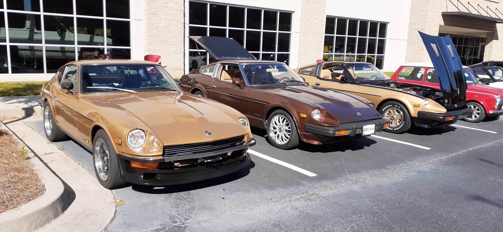
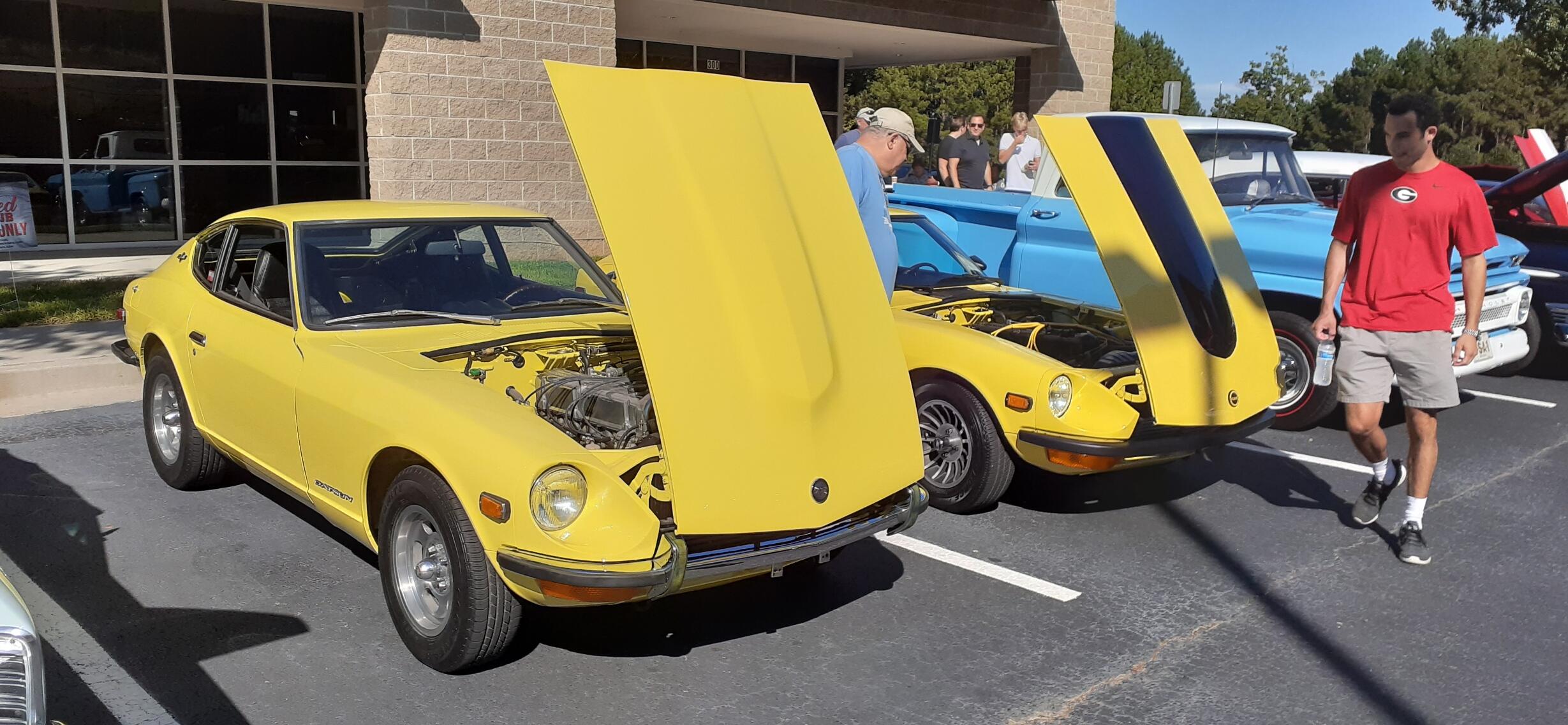
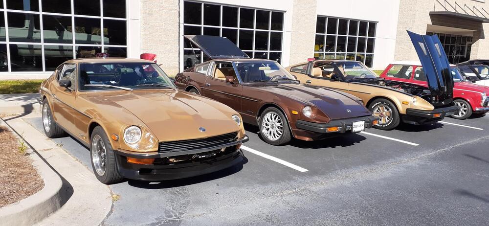
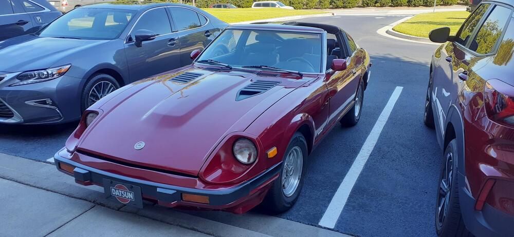
It's false Fall in Georgia. That means for a while we will have cooler temperatures for a short while, followed up with a last blast of heat before true Fall. Anyway, the conditions were great for going to a Saturday morning car meet. As a matter of fact, the weather was so nice, several others decided to bring their Z cars out, too. The two yellow 240Zs were purchased through BaT. One of the owners has been to a Georgia Z Club meeting, though I don't know if he joined, yet. I ended up diagnosing "lack of cabin heat" issues on both. The brown 280ZX and black gold AE are both owned by fellow GZC members. All I can say is that the 260Z felt great on the roads with the new inner LCA bushings. I need to consider doing more suspension work on the 240Z to keep pace.

-
Did you test them with the bulb socket re-installed? The ground for the 240Z gauges is the gauge body. Another problem could be some LED bulbs are positive ground. I found that issue early on when I started experimenting with LED bulbs. Just make sure the dimmer is turned all of the way up. However, LED bulbs tend to be less voltage sensitive than incandescent bulbs.
-
I thought this link was interesting: http://commons.princeton.edu/58-tiger-cub/wp-content/uploads/sites/75/2018/08/ignition_waveforms.pdf It talks about how to use the analyzer to diagnose the engine. If you watched the video I made, you will see the voltage at the firing line vary. I have another video where I used the inductive probe on cylinder #1. From that, I can see which cylinders have the most of the anomalies happen and possibly optimize the spark performance.
-
I hope this adds to the discussion. After watching a couple of videos that @Captain Obvious provided me links for, I bought a 20:1 attenuator for the voltage probe. I hooked up the spark induction probe on the coil wire and shot some video while monitoring my 240Z with a Pertronix Ignitor II. Maybe tomorrow I'll shoot some more video with the 260Z using the ZX distributor. Here is one of the videos the good Capt sent me: I'm not sure in my video if I'm confusing voltage kick with firing line. I noticed a lot of variability in the voltage peak at the firing line. I also noticed as the engine speed increased, I couldn't see the voltage at the coil as easily on the scope.
-
-
Maybe shoot a video so we can hear the noise.
-
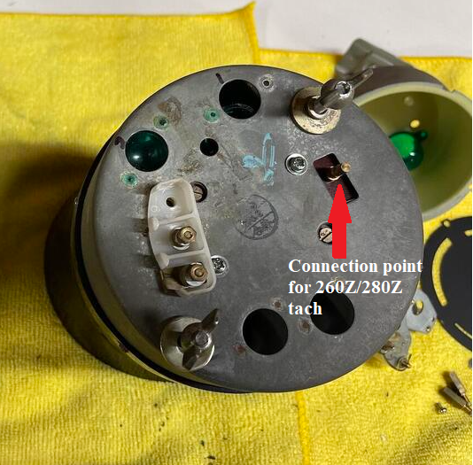
Here's the follow-on question. Did the PO get the resistor installed in the circuit? The design of the tach circuit for the 260Z/280Z 3 wire has a 2.2kOhm 1/2W resistor between the tach and the negative post of the coil.
-
Yes, you have to fool the charger to get it to start. You can do that by having a jumper to a battery that you pull. However, it sounds like your method worked, so there is that. Now here's the next question. Has the wiring in your car been modified for the 3 wire tach? The stock wiring in a 240Z is for the 4 wire tach.
-
I think this link will add to the discussion: http://www.atomic4.com/dwell.htm The title is What is Dwell Management and Current Limiting?
-
Well, I got my old wire tracker out. At first it didn't want to behave, but soon I was getting a good tone from the end of the wire to the gauge.
-
I have the HF unit, and I actually used it at work...about 14 years ago. That was for wiring in a bunch of metal boxes, and I didn't get a bunch of false readings. After a while, I got to where I didn't need it any more. Does it look like your harness has been altered/modified? I might have to dig my tracer out and play with it again.
-
You may have misunderstood. It could be at the bullet connector. You might not be able to see it, especially if it's corrosion. Also, there could be corrosion at the connector between with engine harness and dash harness.
-
Yep, I was talking with @Captain Obvious, and he pointed out the tachometers were different. Apparently someone converted a 260Z/280Z tach to fit into a 240Z. The wing nuts were added to the tachometer
-
My friend, Google, found a link that led me to this: http://www.mgb-stuff.org.uk/tachtest.htm
-
It would be highly unusual for a wire to break in a wiring harness unless the harness was pinched hard or pierced. The usual suspects would be where the connectors are attached to the wire. That would be fatigue breaking the strands or corrosion. However, if you wanted to look for a break in the wire, you would need something like this: https://www.amazon.com/Electrical-Wire-Tracer-Continuity-Automotive/dp/B08L6NYQYK You would detach the C1 connector and clip the red lead to the yellow wire. Then clip the black lead to ground. You would use the probe to "sniff" the wire through the harness, and if you lose signal, that would indicate a break. The bottom line is that you should inspect the connectors carefully at both ends (C1 and at the sensor).
-
Me! Me! Me! I want to get geeky! I even started playing with the inductive pickup I bought for my scope. I really need to re-familiarize myself with working with o-scopes. It was a LONG time since collage.
-
I should add that for top dollar, get photos underneath the car and all over the engine bay. Also take close up photos of the rust prone areas.
-
If you have Hagerty, you can use their pricing guide. I used to think it was high, but the market caught up for the most part.
-
You ought to invite me up there sometime.
-
Here is one thread I found: Some internal photos in this thread:
-
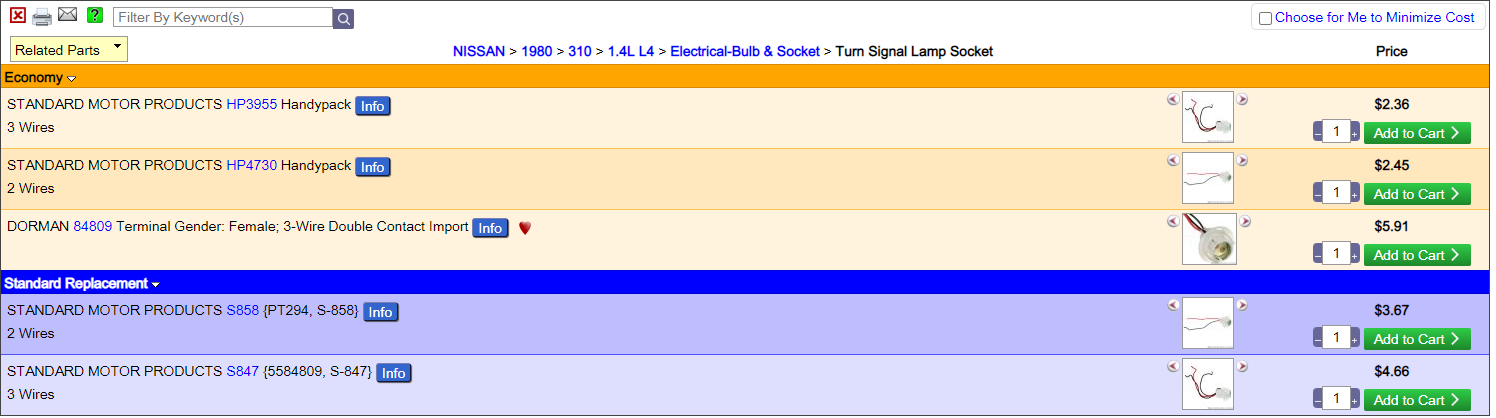
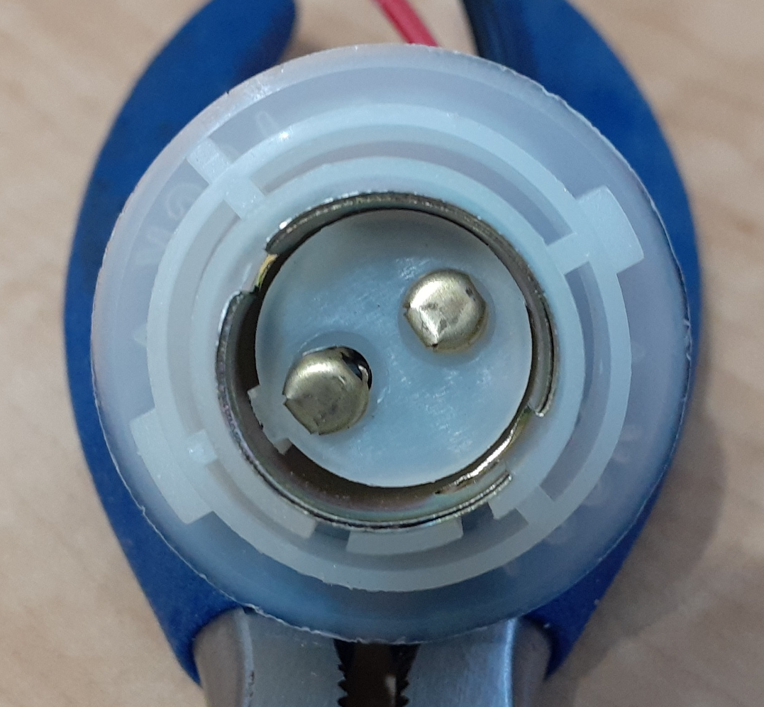
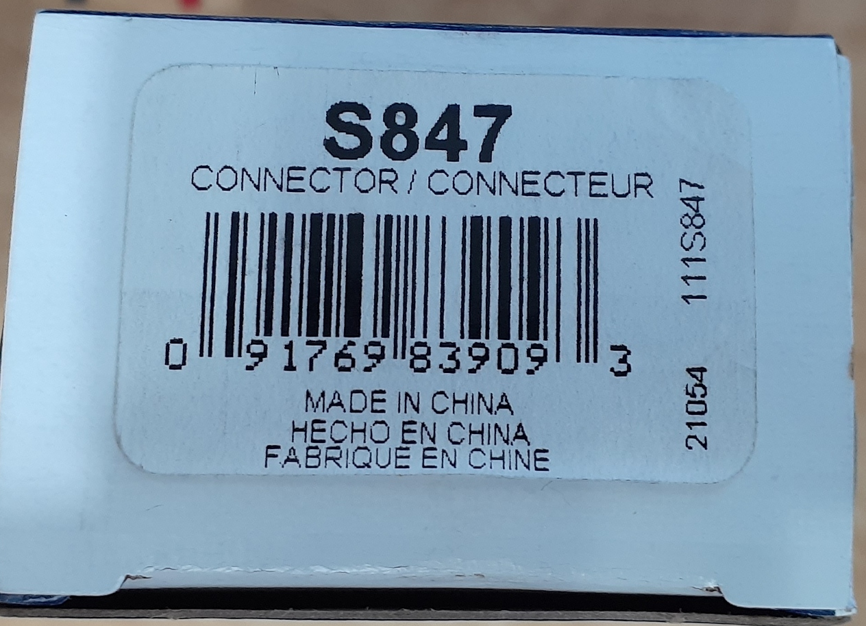
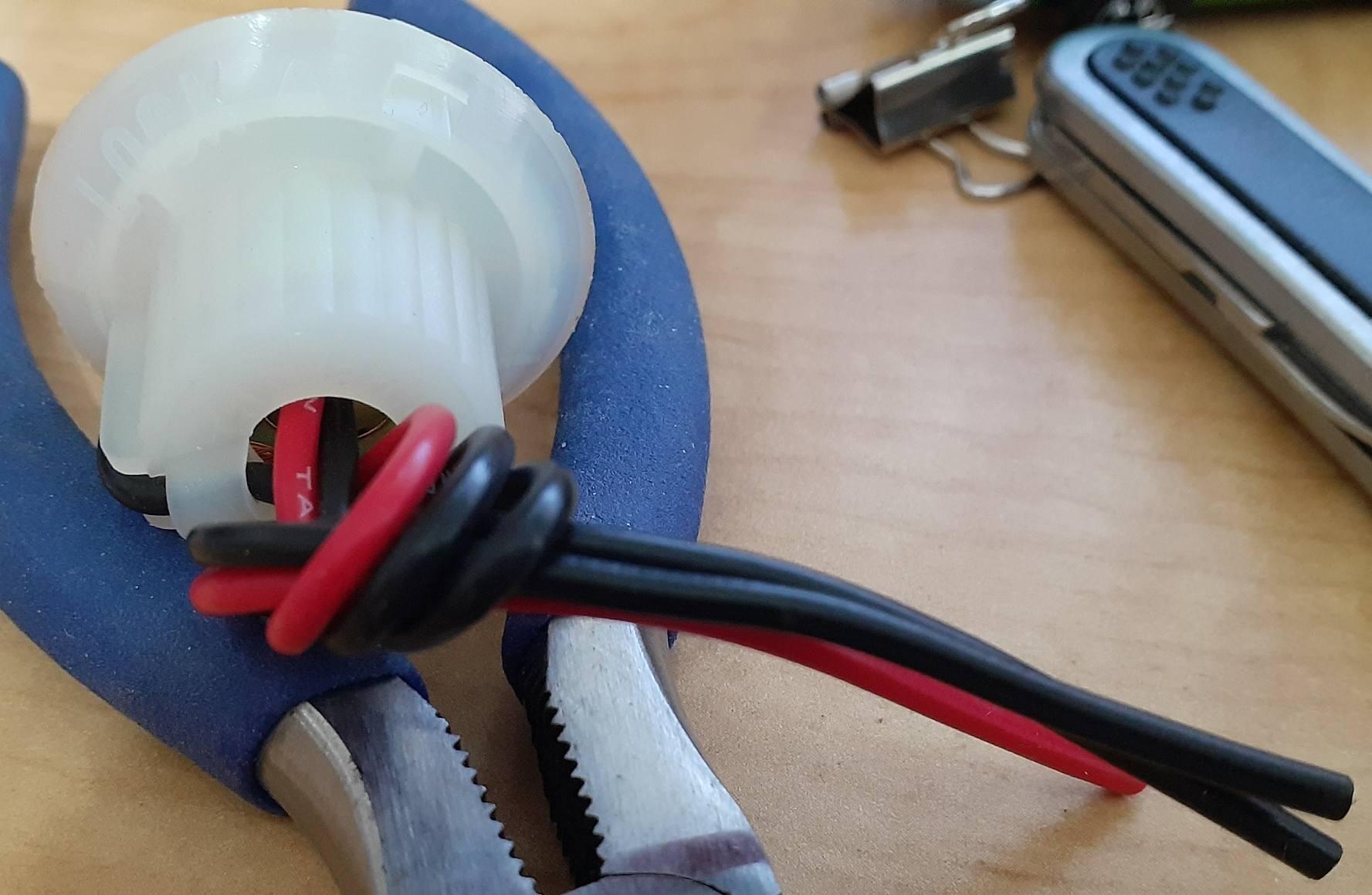
Yeah, I put some more on order from Amazon after I confirmed the fit. Looking into it more, I looked on Rockauto for the fitment of the S847 and looked at the socket part numbers for those cars. It looks like there are some alternative part numbers for the 1156 and 1157 style sockets.

-
Somewhat as a follow-up to my earlier thread: I purchased an SMP S847 socket. I tested it out in my 240Z, and it seems to fit just fine.


-
That's the thing. Any of us (and that includes me) can make those little mistakes, often times not even realizing it happened. I've done things like try to start the car without the wire on the coil or with the rotor sitting on the fender. When it's not as obvious, it's easy to get frustrated and start loading the parts cannon to replace all of those bad parts that aren't really bad. In my friend's case, I could hear his frustration as he repeatedly swapped in parts with no success. That's why I went over to his place with the plan of getting a baseline and examining each part and correct each issue I encountered. This time, it was an easy solution.
-
I don't think it has changed since a year ago.