.JPG.cfcada9cf1c1b502df3f5f2f2ca3ff36.JPG)

SteveJ
Free Member
-
Joined
-
Last visited
Everything posted by SteveJ
-
 That's a good piece of the puzzle. Did you have the points ignition or a first gen Pertronix in the car when he did that? The worst case scenario is that I can probably walk you through making a replacement for that wire that you can "graft" into the dash harness. You know you wanted to have a reason to pull the dash. 😉
 -
-
-
I don't know if I've ever heard anyone say they weren't happy with Ron's work. @zclocks
-
Get resistance readings, not tone. I think I have mentioned in one of my YouTube videos that you can get a "false positive" with a tone. Also please be more descriptive with your measurement techniques and testing procedures. Where you put your probes is important. Here's an example, for the B/Y wire, it goes through the solenoid and on to ground. If the wire is connected at the solenoid, you could read the resistance of the wire in the solenoid when doing a measurement. Depending upon how your meter is set up, that may set off the tone. If you're not too experienced with multimeters, these videos may help.
-
-
You might want to read through this thread:
-
-
-
Several good excuses to come down to the Atlanta area in your Z: The Mitty - Vintage racing weekend at Road Atlanta on the last weekend in April https://hsrrace.com/themitty2022/ Fall Historics - More HSR vintage racing at Road Atlanta https://hsrrace.com/fallhistorics2022/ Z Nationals - I usually just go to the track day on Friday when the show is at Z1 Motorsports. With their expansion, they don't have space on their grounds for more cars. This year track day is at Atlanta Motorsports Park. https://www.znationals.com/
-
I told you to disconnect the engine harness from the dash harness and re-test. If you test the engine harness and find no short, you can suspect the short is in the dash harness. That black/white certainly got overheated. You are quite possibly correct that it is on the ignition circuit branch out to the ballast resistor. You can verify that, but it takes using a multimeter with long leads. By the way, this can be handy for that purpose: https://www.harborfreight.com/electrical/electrician-s-tools/30-ft-retractable-test-leads-58024.html (Note, they are only designed for low current applications.)
-
Thank you. I'm fortunate to live in a Z oasis in the Southeast. Yes, the 260Z was at Birmingham. I drove it out to Barber for Parade Laps & to watch autocross, and I took it to Little Talladega to shoot photos and video for the second track day. I had it at the People's Choice show, too. It was parked next to the blue 280Z with the RB swap. My car is on the bottom row in the middle, just above the ZCCA logo..
-
-
The closest I could find with a quick search was here: https://zcarsource.com/seat-upholstery-set-240z-70-73-butterscotch-vinyl-new/
-
For the IAC, if you need a switched source, the black/white at the voltage regulator is a better choice. That wire is electrically the same as the black/white that goes to the ballast resistor. The only thing is that the wire at the VR goes through the fuse box before going out to the VR. If the insulation ever gets damaged, the fuse should give some protection to the rest of the wiring.
-
-
No, the green/white is not a ground. Why do you think it might be? You should not dismantle this circuit unless you have another source for a tachometer signal and are not using the 240Z tachometer. I haven't followed your build thread, so I don't know if you are planning on using coil packs. Otherwise, you also need this circuit to provide 12VDC to your coil. If you don't want your wiring to burn up, I would suggest you use a fused source for the IAC, such as the black/white at the voltage regulator connector. The ignition circuit you are thinking of using is a poor choice for the IAC.
-
Now that you have isolated the wire, disconnect the connectors between the dash harness and engine harness that have a black/white wire and re-test. If you have taken the dash out of the car during the build, I would wonder if maybe pinched a wire or the wire harness in the dash harness. Also look for previous owner modifications like a relay for a thermostat-controlled fan.
-
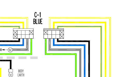
Both black/white and the green white wires show up in wiring diagrams. See attached for the highlighted path. One black/white goes from the ignition switch to the ballast resistor. The green/white lands on the other side of the ballast resistor and goes to the tachometer. The other black/white comes out of the tachometer and goes to the coil positive. If you think you have a short in the circuit, unplug the 4 wire connector from the back of the tachometer and lift one of the wires off the ballast resistor. You have isolated the wires from one another and can measure resistance to ground at each. Ignition Circuit.pdf
-
After a little research, I would concur with your assessment.
-
This AN603, @Captain Obvious? https://shop.ectransistors.com/PANASONI-AN603-CDIP-14-.html
-
Apparently DQ also has an article on grafting in the tach from an S110 200SX. There are several NOS tachs on ebay now. It's not cheap, but it would probably be a fix Cody could enjoy for a long time.
-
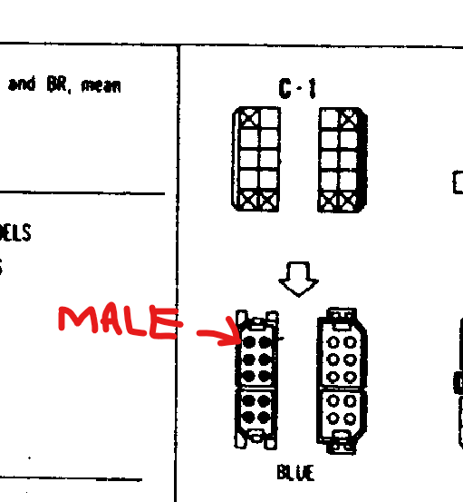
@Terrapin Zis correct. Those connectors are also color coded. C1 is blue as indicated on the wiring diagram. Another convention, knowing which side has the male pins: So in the wiring diagram: The male pins should be on the engine harness side, and the female pins should be on the body harness. If you see how the connector is shown in the wiring diagram, there are no wires going to where the Xs are.
-
Can you tell us the year FSM?
-
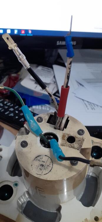
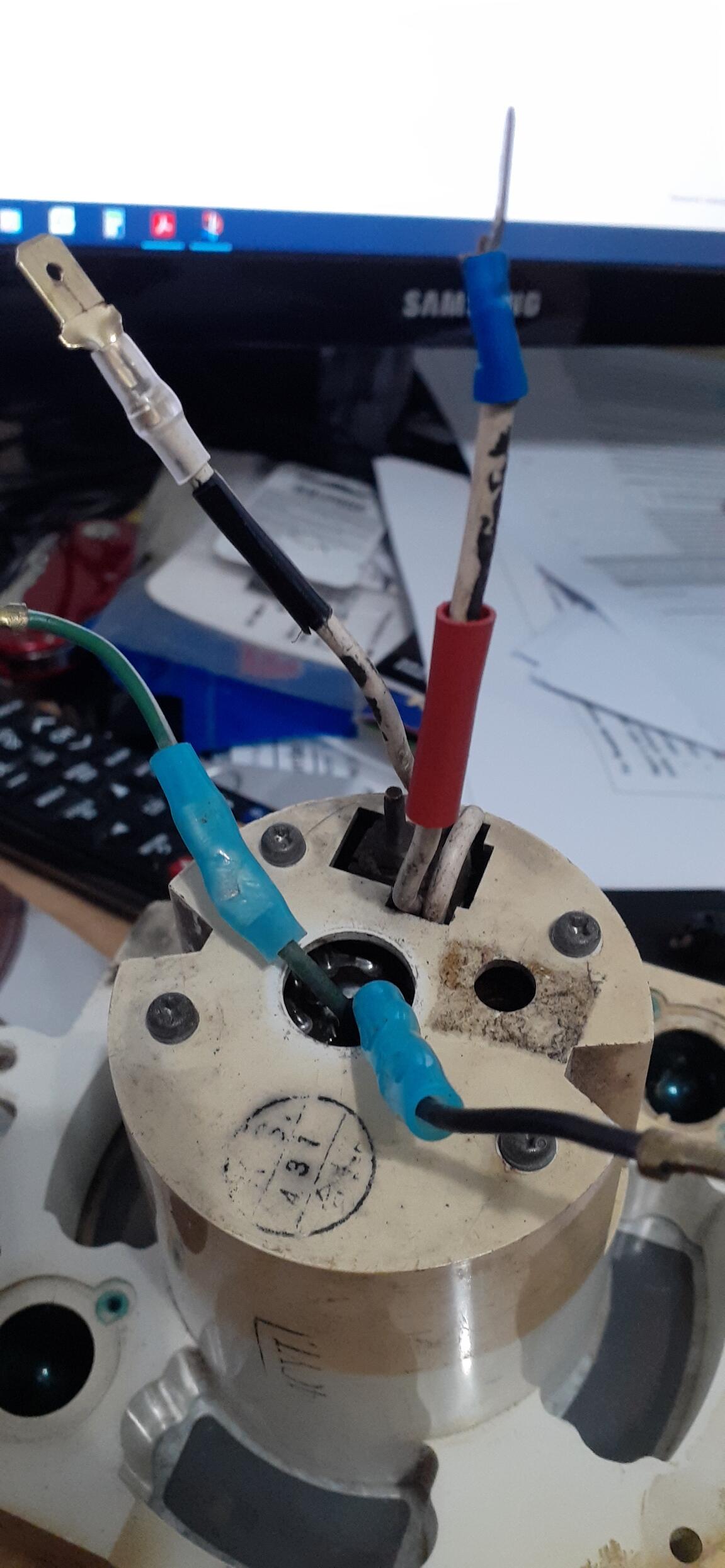
Not surprisingly, there was no change. But I did take the time to mark the polarity on the tachometer wires to make it easier to identify which wire goes where in the future. I couldn't find my red electrical tape (that had been sitting in the same place in the garage for about 10 years until I reorganized last year), but I did find some red heat shrink that fit over the spade connector. At least I had fun testing. I'm interested in Bruce's analysis. I could do a visual on the discrete components, but I think Bruce has better skills in that realm.