.JPG.cfcada9cf1c1b502df3f5f2f2ca3ff36.JPG)

SteveJ
Free Member
-
Joined
-
Last visited
Everything posted by SteveJ
-
 The plates the in battery can become coated with lead sulfate, especially if the battery drains. So while the battery has 12 VDC potential, the plates are not exposed enough for electrons to flow. That limits current. A way to measure this is to measure voltage at the battery after putting the key in the run position. (Notice that I didn't say, "start".) If the voltage at the battery drops significantly with no accessories going, it is gone. If you still have 12 VDC at the battery, then measure the voltage while having someone hit the starter. If the voltage at the battery drops below about 9 VDC or so, it is not strong enough to engage the solenoid or starter. If the battery still has good voltage, measure voltage at the solenoid and coil like I said in the first post. I know you have a Harbor Freight nearby, so it should be no problem for you to get a cheap multimeter. As I mentioned in the previous reply, hacked wiring is usually a way of fixing a problem properly. Don't be surprised if other electrical gremlins appear. By the way, I have family in Huntsville, so I get out that way from time-to-time.
 -
The click you heard was the accessory relay. That is normal. Things to check: 1. Fusible link 2. Wiring in the steering column. Unfortunately, the wiring has been hacked, as you noted. Who knows what was wrong before someone attacked the wiring with diagonal cutters? The voltage regulator would not keep the car from starting. Don't worry about it right now. Download the 1971 Chasis Supplement from Xenons30. It has the wiring diagram. The link is below. Using a positive to negative convention for the circuit: When you go to start your car, 12 VDC+ goes from the White/Red wire to the ignition switch. It goes out the Black/Yellow wire to the inhibtor switch (no function in the manual) and on to the solenoid. The switch also completes the contact for the Green/Blue wire. This wire joins the Green/White wire to provide 12VDC+ to the coil during starting. (This bypasses the ballast resistor.) If you don't have 12VDC at the coil and at the solenoid, the car won't start. Where in North Alabama are you? Send me a PM if you're not comfortable answering in an open forum.
-
The BD kit does have some glaring shortcomings since it is generic, and the relays are not standard relays. The there also aren't inline fuses, so those should be added. I bought the kit and proceded to replace most of it. The only good thing about it for you would be the fact that it has separate positives for high and low beam with the ground being common, so it would have worked in that respect for you LED headlights.
-
Given the other history you've provided, start searching for damage to the red wire coming out of the switch and going to the fuse box. Look carefully for damaged/burned connectors.
-
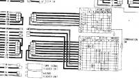
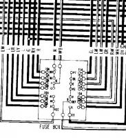
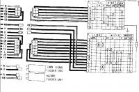
When you say you're not getting power to the harness for the headlights, what do you mean? The 12VDC+ for the headlights is the infamous White/Red wire. It goes into the switch on the right, and comes out through the Red wire when the headlights are in the #2 position. The Red wire travels to the fusebox and splits into the left and right fuses, coming out Red/Yellow and Red respectively. The 12VDC+ travels to the common pin for the headlights. Two wires come out of each headlight. One wire is Red/Black. The other wire is Red/White. The two Red/Black wires join as do the two Red/White wires. The wires then go back to the combo switch on the turn stalk. If the switch is in the low beam setting, the Red/Black wire will be connected to ground via the Black wire. If the switch is in the high beam setting, the Red/White wire will be connected to ground via the Black wire. Get out the wiring diagram & multimeter, and start digging. If you get stuck, post a message describing where you got stuck. Don't be stingy on the details, either.
-
Ben, you're trying to install led headlights in a 33 year old car. Don't you think that draws some notice? I don't have pictures of Dave's relay design installed, but I do know that a lot of people are happy to have them.
-
The White/Red wire is the main 12VDC that goes into the ignition switch and out to the key-controlled circuits. The fact that it has been hacked it disconcerting. Are there signs of circuits having shorted out in the past in your wiring harness? IPOs (idiot previous owners) are especially dangerous when it comes to electrical wiring. I'm sorting through some of that now with my 74. Anyway, it sounds like you're getting yourself on the right track. Make sure the wires are correct. Then you can test components.
-
Okay, what wires were missing? How did you discover they were missing? Did the car run before you replaced these wires? Were you referring to the wiring diagram in the FSM to replace them? How did you replace them?
-
If your engine is not solidly grounded to the chasis, you could have problems with the spark, but that's off the high side of the coil. But for the negative probe, were you touching the chasis, the engine, the other side of the resistor? Common electrical problems for S30s include Bad fusible links Bad fuses Damaged/Corroded connectors Connectors that came undone during repairs Damaged wires Bad relays/electronics Poor connection to ground. With the multiple problems you described, I would think bad fusible links or disconnected/bad connectors. Sometimes you have to start at one end of the circuit (positive or negative battery post) and work through the wiring diagram to get to the other end of the circuit. At least the wires are color coded.
-
1. What ground wire are you referring to? 2. Put the year of your car in your posts. Not everybody knows you have a 76. Different year cars are wired differently. 3. Where were you touching your leads to when you measured 1.5 VDC around your ballast resistor. (Pictures don't hurt, especially when you add arrows to point to things.) 4. Did you check your fusible links? DO NOT rely on visual inspections. Remove them and test resistance/continuity. 5. Did you take voltage readings at the fusebox? What were the results? 6. Are you sure you used the proper rated fuses? Are you sure the fuses are still good?
-
http://www.thezstore.com/page/TZS/PROD/30-7314
-
If your electrical skills are lacking, it could be a challenge. You could also contact Dave, aka Zs-ondabrain. He has designed a plug & play for the 240Z. I think he has also made a few for 280Zs. Given the choice between the two, I'd pay extra for Dave's if I were you. You will receive better instructions and support.
-
Keep in mind that coolant in the exhaust will give a sweet smell.
-
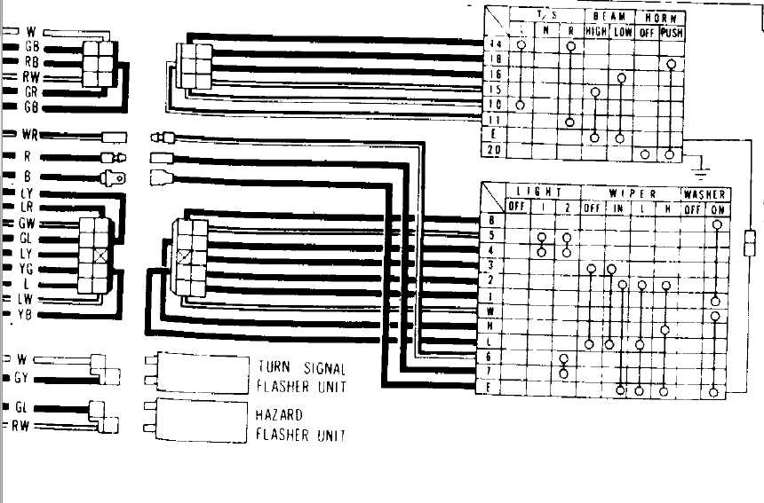
Arne said If you look at the link I posted, you will see the circuit has 2 (two) 12 VDC+ wires and a common ground. If you look at the wiring diagram for your car (or the images I posted), you will see 1 (one) 12VDC+ wire and two wires that could go to ground. You select your path to ground with the high/low beam switch. I understand perfectly well what is going on. I offered to draw up the relay circuit for you. I can't help it that you don't understand. Just buy the relay kit in the Black Dragon catalog. If you figure out how to wire it in, it will fix your problem. There is a way to fix your problem without installing relays, but it involves re-wiring your switch. I wouldn't recommend going down that path.
-
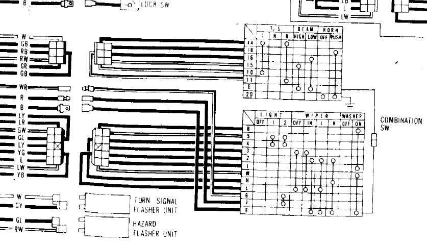
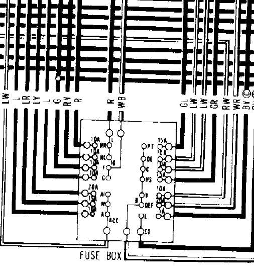
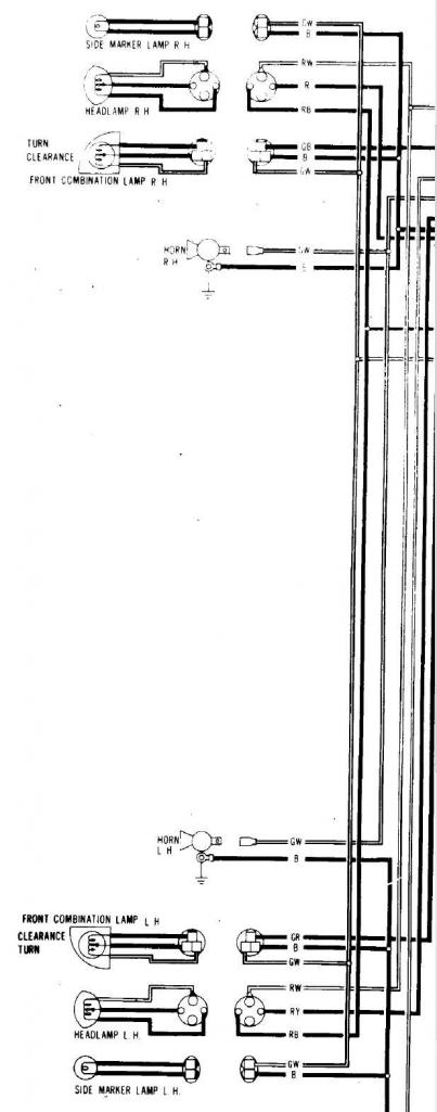
I have studied the wiring diagrams from many of the FSMs' date=' especially after others pointed out to me that the 70 & 71 240Zs have their headlight circuits wired differently than other S30s. I have converted both of my cars to relays for headlight controls. I do know what I'm talking about, and yes, I am an electrical engineer. I'll step you through the circuit, using a positive to negative convention. 1. 12VDC+ comes into the combo switch on the right using a White/Red wire. 2. When the headlight switch is in position 2, it completes the contact and goes out the Red wire. (See the first attachment.) 3. The red wire goes into the fusebox and goes through two fuses. The fuse for the right headlight has a Red wire. The fuse for the left headlight has a Red/Yellow wire. (See the second attachment.) 4. The Red and Red/Yellow wires travel to their respective headlights and land on the common pin for the headlights. Two wires come out of each headlight. One wire is Red/Black. The other wire is Red/White. The two Red/Black wires join as do the two Red/White wires. (See the third attachment.) The wires then go back to the combo switch on the turn stalk. 5. If the switch is in the low beam setting, the Red/Black wire will be connected to ground via the Black wire. If the switch is in the high beam setting, the Red/White wire will be connected to ground via the Black wire. (See the first attachment.) At no time does the polarity change. The path to ground changes. Since the D in LED stands for diode, yes, polarity is important. Did the headlights come with instructions? Look for any guidance on wiring. My guess is that the common pin is supposed to be grounded, as I said before. If you still don't believe me, take the voltage readings at the headlights again. However, take out BOTH headlights. With the switch in low beams, you will find that you have 12VDC (probably less) between two of the three pins. When you change it to high beams, the pin that was positive before will still be positive. The negative will go to the third pin.

-
Have you tried sending a PM to Dave, aka Zs-ondabrain? You apparently miswired something.
-
Switching polarity? Nope. They don't. The stock wiring on the 280Z has the 12VDC going to both headlights. The return wires go to the high/low beam switch. That switch selects the path to ground. Look at the circuit that Daniel Stern uses to demonstrate the value of relays. Note that the ground is common and you have two 12VDC sources coming in. If your LED headlights require a common ground, you could put in relays that utilize a common ground. If you don't understand what I'm saying, let me know, and I'll draw up the circuit for you.
-
aj, Did you look at your plugs? What did they look like?
-
Well, the ZX distributor's module is mounted on the distributor. I'm not sure if the 280Z had that. Don't they have a separate box? For the 240Z & 260Z, it does away with points. Also there were a lot of 79-81 ZXs made, so parts are plentiful.
-
I replaced the boot on the firewall for the throttle today. I also detached the speedometer cable from the speedometer to replace it. I noticed a wire going through the grommet for the speedometer cable, so I traced it. One end went to the positive side of the coil. I followed it under the drivers seat and up the back and under the carpet on the rear deck. It continued over to the passenger side taillight where it was poorly jury-rigged to the fuel pump. The wire was nice and brittle for the full length and poorly spliced in a couple of places. After I replace the speedometer cable, I'm going to look at the fuel pump relays to make sure they work.
-
Yes, the ZX distributor swap has been done to many cars. My 260Z has it, and I'm going to do it to the 240Z.
-
-
If you search this site, someone posted quite a few links within the last year for Z suppliers.
-
With some studying of the wiring diagram, that could be figured out. For instance let's look at the switch. From the attached image we can determine the following connections at the different switch positions: Off LY - YB In LY - YB YG - WR (12VDC) Low WR - YB WR - YG High WR - LY WR - YB Tracing those wires will probably take us over to the amplifier circuit. From seeing what connects where and the other diagram in the BE section, we can probably figure out the function.
-
So he was using a relay with 2 form A contacts?