.JPG.cfcada9cf1c1b502df3f5f2f2ca3ff36.JPG)

SteveJ
Free Member
-
Joined
-
Last visited
Everything posted by SteveJ
-
 I would guess that something is mis-wired.
 -
Here's what @Yarb is talking about: https://zcardepot.com/products/clutch-hose-metal-tab-frame-rail-510-240z-260z-280z
-
He could have done something really weird like converted the carburetors into throttle bodies.
-
Not starting means you're missing fuel, spark (includes timing), or air (compression). Figure out which of the 3 isn't right.
-
I cannot confirm the effect on the life of the TIU, but the lack of current limiting and ballast results in saturation of the coil. The reduces the amount of energy that the coil can send out to the spark plug. It will probably reduce the coil life (Think insulation breakdown from the higher current.) and is more likely to leave you stranded somewhere. The blue wire coming off the coil and going to the TIU also branches off to go to the ECU. The ECU senses when the TIU grounds the blue wire to fire the coil. There should be very little current going through that wire, but I don't know the voltage tolerance of the ECU on that circuit.
-
Just to make sure it was clear about what I was asking you to check on your plug wires.
-
@Zed Head is correct. That is a 260Z distributor. It never had points. The TIU should be mounted in the passenger footwell. It looks like this. It sounds like you may be thinking of the 280ZX distributor that has the ignition module mounted on it. The 280Z had a similar ignition set up to the 260Z. YES, there is supposed to be a ballast resistor. I suggest you download a copy of the factory service manual from here: https://www.classiczcars.com/files/category/12-260z/ Read through the EE section on the distributor and ignition. It will have information on the timing. As for the title problem, I can't tell by the description, but I would start looking for where you could be losing spark energy, such as through bad plug wires or bad distributor cap. Also make sure your plug wires are fully seated into the base of the terminal on each cylinder and coil post on the distributor. A few months back I was looking at a friend's 240Z with Pertronix that was not going above 3,000 or so RPM. I started going over each part in the ignition and found a plug wire that was not seated properly. It did not show up as a problem with the car sitting still, only while under load. With the wires seated properly, the car ran like a scalded dog.
-
The 78 TIU is current limiting. Even the 700 should have used the ballast resistor or higher impedance coil (3 ohm). For background on current limiting: http://www.atomic4.com/dwell.htm For the ignition system to work properly in a stock configuration for a 75, you need a ballast resistor or 3 ohm coil.
-
Coil = Ignition Coil The coil condenser should be attached to the positive terminal of the coil. The condensers for the charging circuit are not documented in the 240Z wiring diagrams. The 260Z is the first that shows them. There is one on the WR (main) wire and another on the BW wire before the VR.
-
Have you plugged the drain hole for the electric antenna? That's near the exhaust.
-
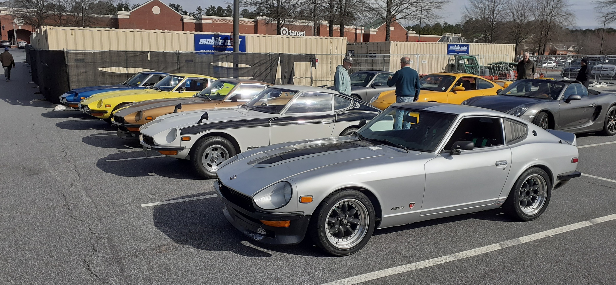
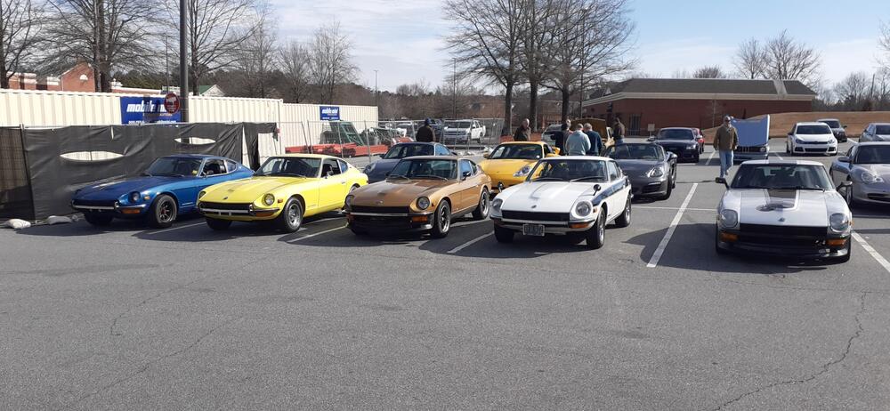
Another weekend, another car meet. There another couple of Z33s that showed up, but they were shy. The silver 260Z had the rare, but coveted, Golden Retriever option.


-
@zspert might be willing to divulge.
-
There are many opinions on distributors. However, keep in mind that you'll need to learn about how your car is wired now before you start to load the parts cannon. Otherwise, I can pretty much guarantee you'll have other problems you'll be chasing. ZX distributor: Easy to implement, but conventional wisdom says you'll have tach issues. (Running this in my 260Z. Keep in mind it has a different tach than the 240Z.) Also need 280ZX distributor mount. Stock 240Z distributor: Easy to implement, but you'll have to learn how to set gap and dwell. I'm not sure about the reliability of dwell meters currently available on the market. May need a 240Z distributor mount. Stock 240Z distributor with Pertronix: Easy to implement, but some people question reliability. (Running this in my 240Z.) 280Z distributor with HEI: More knowledge needed for wiring. Need to have a heat sink on the HEI. Easy to replace failed modules. May have tach issues. Also need the 280Z distributor mount. 123 Ignition: Higher price. May need to tweak the spark curve. Just don't expect to swap out anything quickly.
-
If the freeway traffic is moving (Does that happen in LA any more?), there might be enough air moving through to slow the heat build up, provided that is the cause of your dilemma. Heat is an enemy of electronics. If the car is cutting out sooner in stop and go traffic, that's an additional sign that it's heat related.
-
Immediate cut-off implies electrical. How long are you driving before it happens? Are there any symptoms prior to cutting out, such as the tach needle dancing or the car bucking? How old is the MSD? Have you tried seeing if it's hot when the car shuts down? Is the coil getting hot? (New doesn't always mean good.) You could always tried the canned air trick. Keep a can of dusting air in your car. When it cuts out, hold the can of dusting air upside down and spray the MSD. If the car restarts sooner, then the MSD could be failing. Same thing for the coil.
-
Blessed be the parts hoarders for they shall provide the used parts to keep our Zs alive.
-
I don't think I have any snaps left in my car, so I have to guess on what may be right. My friend, Google, suggested this: https://www.globalindustrial.com/p/universal-snap-kit-10-mm?infoParam.campaignId=T9F&gclid=CjwKCAiAuOieBhAIEiwAgjCvcqgnHHx2mRIvEt3M11PWrGB50NWHk8f1cKk6x45KGXCgQc0t-gWLYRoC8ooQAvD_BwE It's 10mm, so that sounds promising as a start for a car built in Japan. If you want to just find something, search Amazon for screw snaps, and it gives you a bunch of different products.
-
This may help: https://zhome.com/History/ZColorGallary/index.html
-
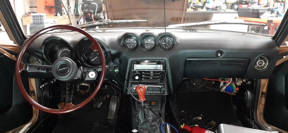
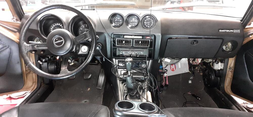
Some of the details will be distorted by the dash cap. And I still don't know how to align the glove box door. I think this really outlines your challenges if you look carefully, aside from the extra holes for the cigarette lighter (higher in the 240Z) and glove box door button.
-
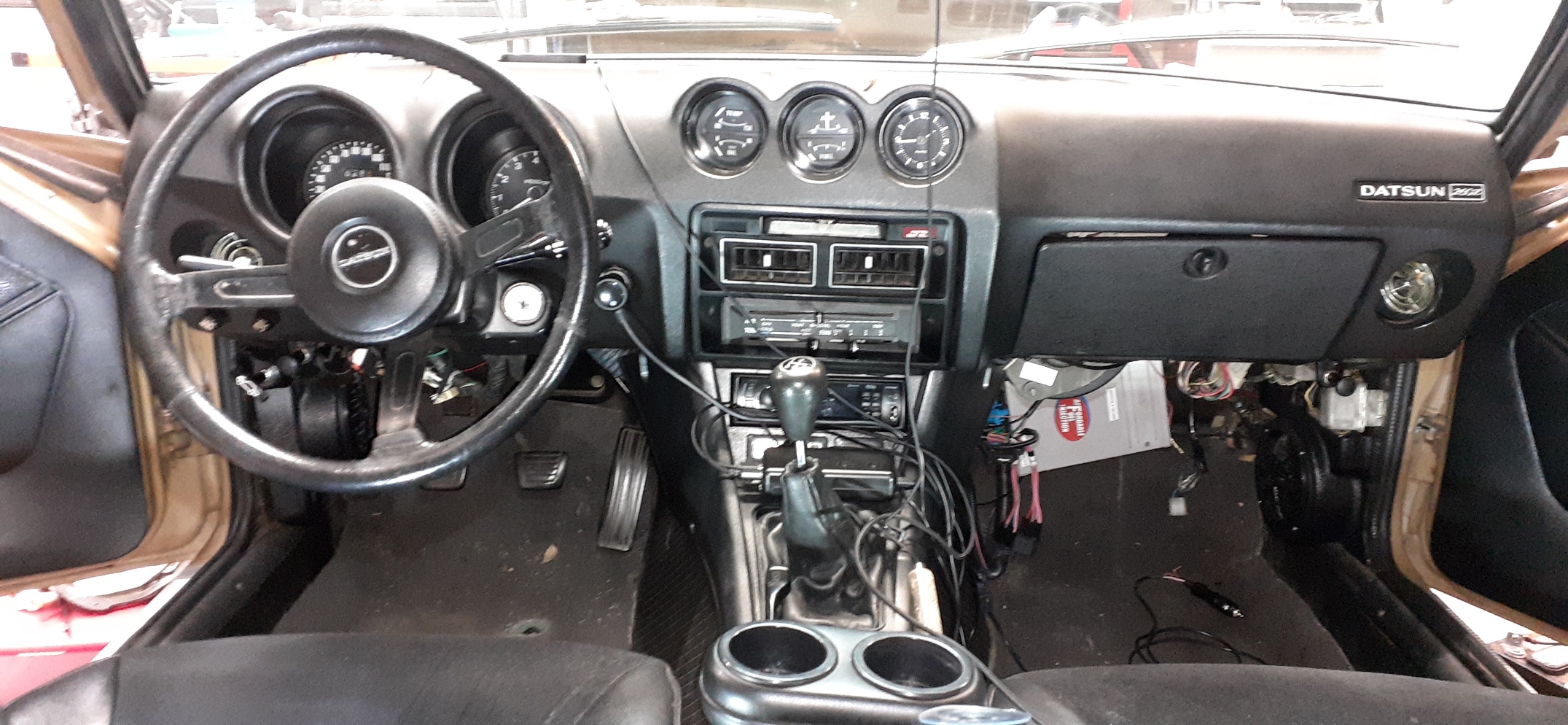
I'm not sure what you mean by the ignition hole. The ignition switch on my 240Z and 260Z are on the steering column. Differences: The 260Z dash does not go down as far as the 240Z dash. The 240Z dash has cutouts for the cigarette lighter and hazard switch. For the 260Z, the switch moved down to the center console. Note the hazard switch hole for the 240Z has variations, too. The shape of the ventilation controls area is different. The gauge lights dimmer and trip reset are on the front of the dash on a 260Z. There is a cutout for the glove box lock on the 240Z. The lock is integrated into the door on the 260Z. There are some contour differences, too. 240Z 260Z
-
I think @Racer X is referring to https://www.240zrubberparts.com/. I don't see one, though.
-
Just remember to get a pre-test before you go for an official smog test. I don't know when you are thinking about moving, but there's no need to get your car labelled as a "gross polluter."
-
I would think the higher compression would drive higher temperatures would drive higher NOx, and my friend, Google, was able to find links to say that is the case. Also, according to my friend, Google, in typical operation the EGR lowers the oxygen concentration and absorbs heat to reduce NOx formation.
-
Headers and EGR delete won't pass the visual inspection. Your car could put out zero CO2, NOx, CO, and HC, but if it doesn't have all of the smog equipment that Nissan installed or CARB equivalents, that's likely a non-starter.
-
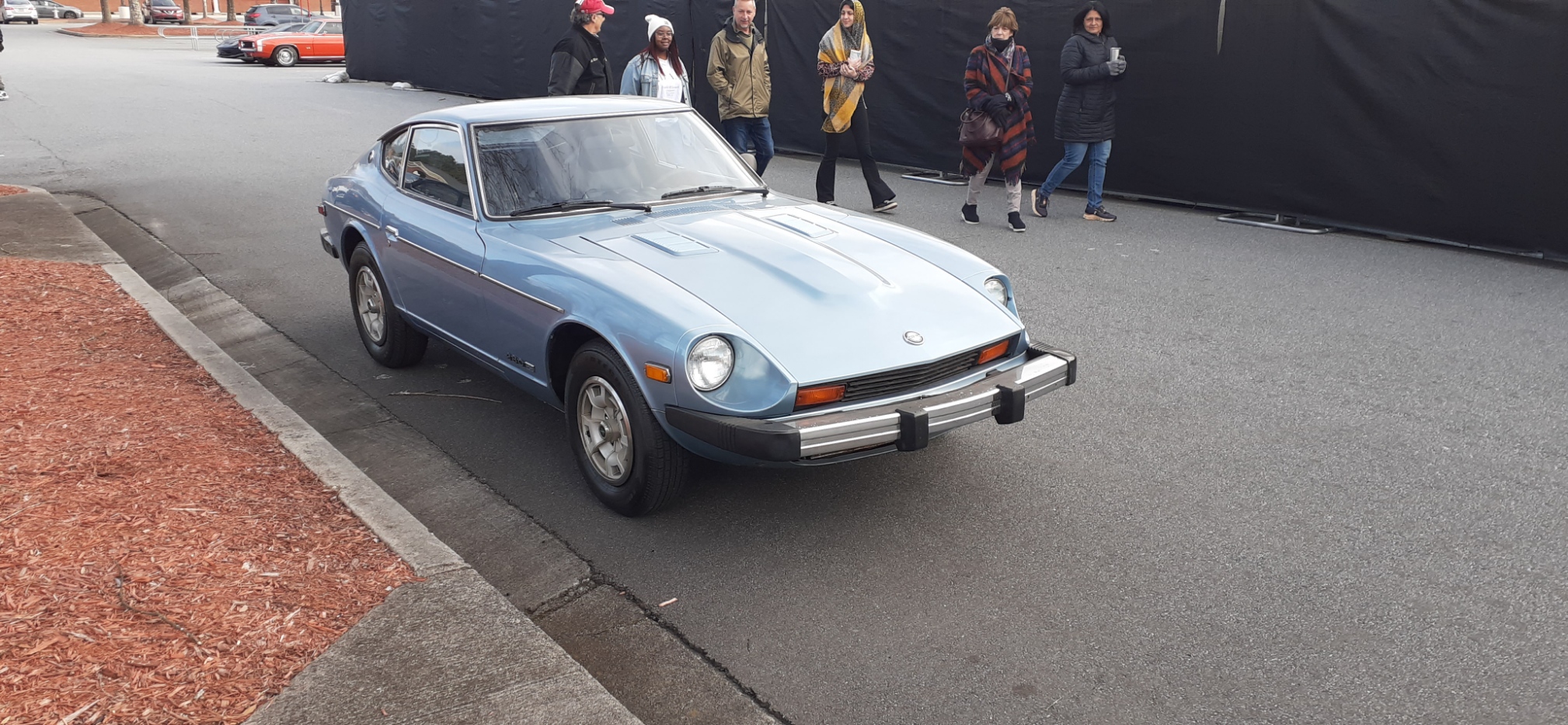
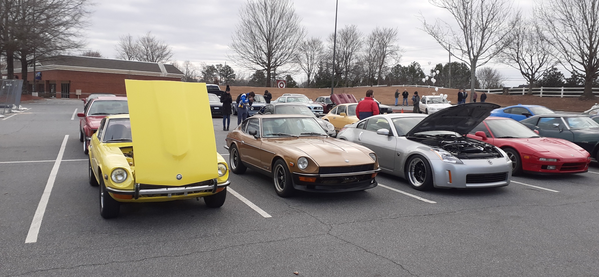
Despite the freezing cold morning air, several of us drove our Zs to a local car meet. We were joined later by a 350Z, and an AE 280ZX.