zclocks
Free Member
-
Joined
-
Last visited
Everything posted by zclocks
-
 Ok, I finally got around to replacing my fuel rail and a few questionable bolts and nuts. When I looked in my 75 280 service manual it says that the stock manifold 8 mm bolts torque is 10-13 ft-lbs and the 10 mm bolts are 25 -36 ft-lbs. My manifold intakes are 14 mm bolts and the exhaust are 12 mm nuts? What am I missing here? Any clarification on size and torque would be appreciated. Thanks
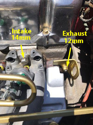
-
You said you had a lot of R12 to work with. I still use R12 in my 75. Where did you get the source of R12?
-
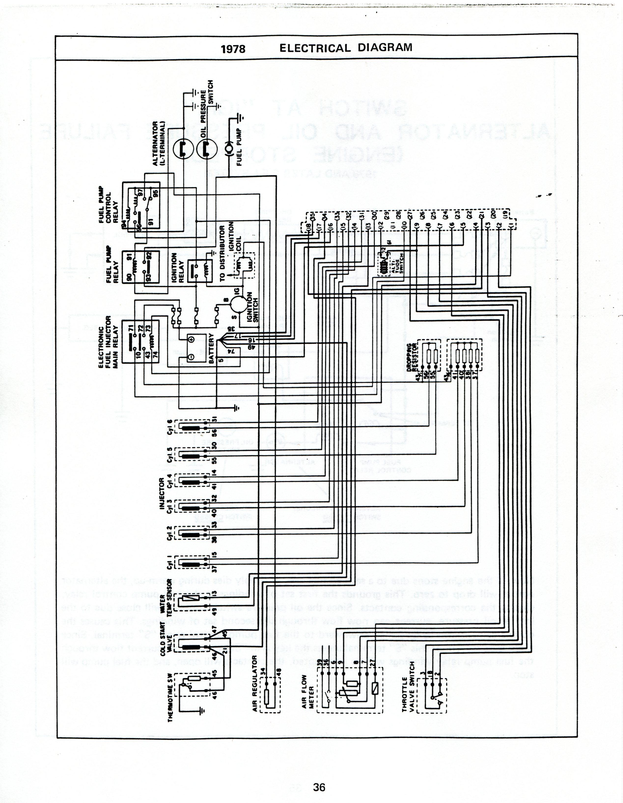
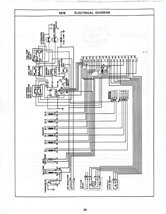
Hi Alex, Congratulations on your first project. First I think we should back up and see what year you have. I have a 75 and 75-77 FI was much the same. The FI manual you need is the 1980 version as there are changes. In 78 the FI relays were located under the hood according to the FI manual and they show 4 on the schematic just like in your photo . Are you sure the car is a 77? Did you look at the production date on the jam of the drivers door? If this is a very late 77 it might have the newer 78 relay upgrade. Maybe some one of the 77-78 owner could chime in? Look at the items I've enclosed and if you have the 4 relays then the schematic could help you track down the wiring, it's for a 78. I have seen both FI manuals somewhere free to down load , but if not I have copies of both you can have. It's almost essential to get a Datsun 280z Service manual as it is really the best for an owner to have.
.thumb.jpg.0a9797b47bbf15115048b5d881379358.jpg)
.thumb.jpg.201cf7030f7c0cfbc3b508882e389524.jpg)
-
Captain, Yes, I do have a signal gen and I found my Tach extension harness. Now if I could only find the 2 tachs I have. All this searching I found parts I didn't know I even had.
-
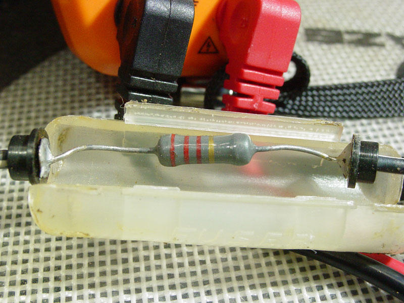
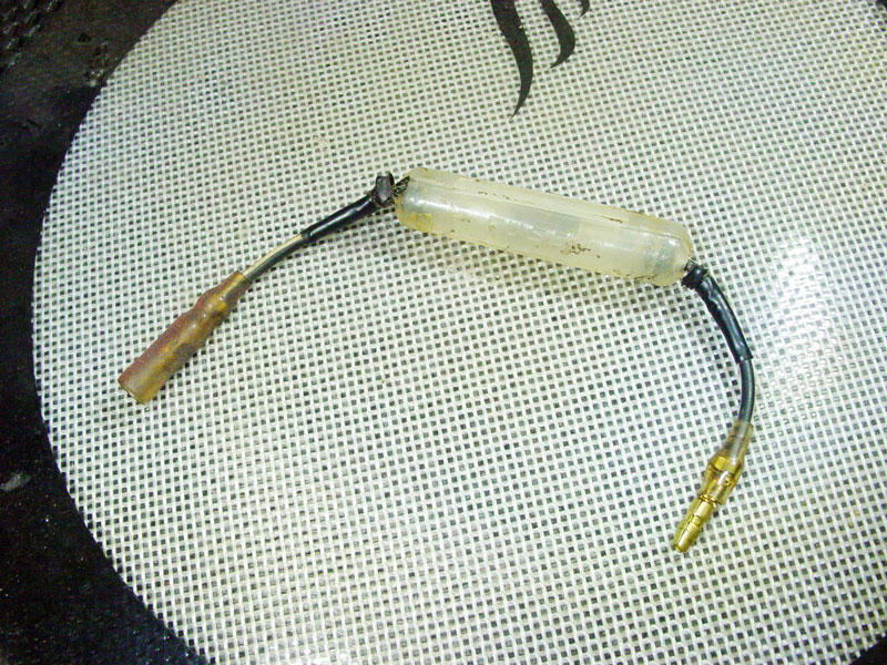
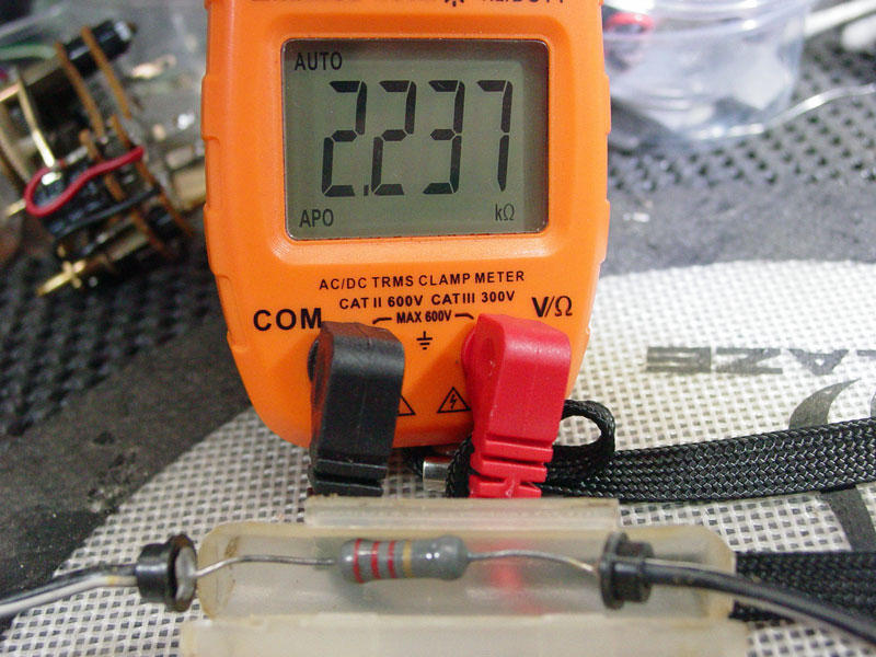
Hey zKars, I found my tach resistor on my 75 280z . It was very close to where yours is, but my resistor holder is completely different. It would appear to be the old style FUSE holder. I guess in Jan of 75 that's all they had! My resistance (2.237K ohm) is close to yours and it looks like a 2 or maybe 5 watt resistor. Hard to tell anymore. The connectors are good , but I like all connections crimped and soldered. Just another something to do.
-
Zed that's funny. I don't ware a watch either. When asked what time it is I usually say day time or night time!
-
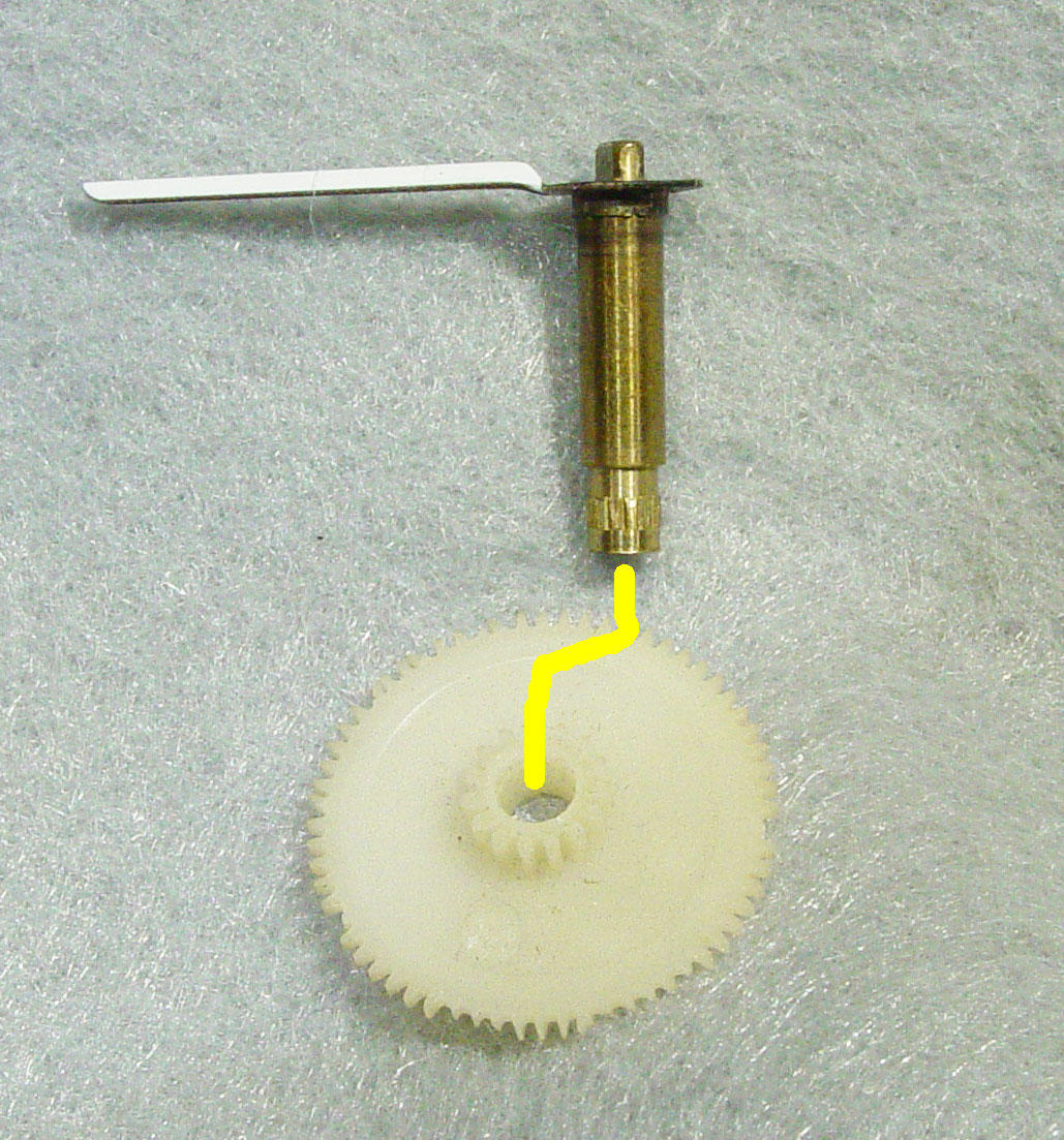
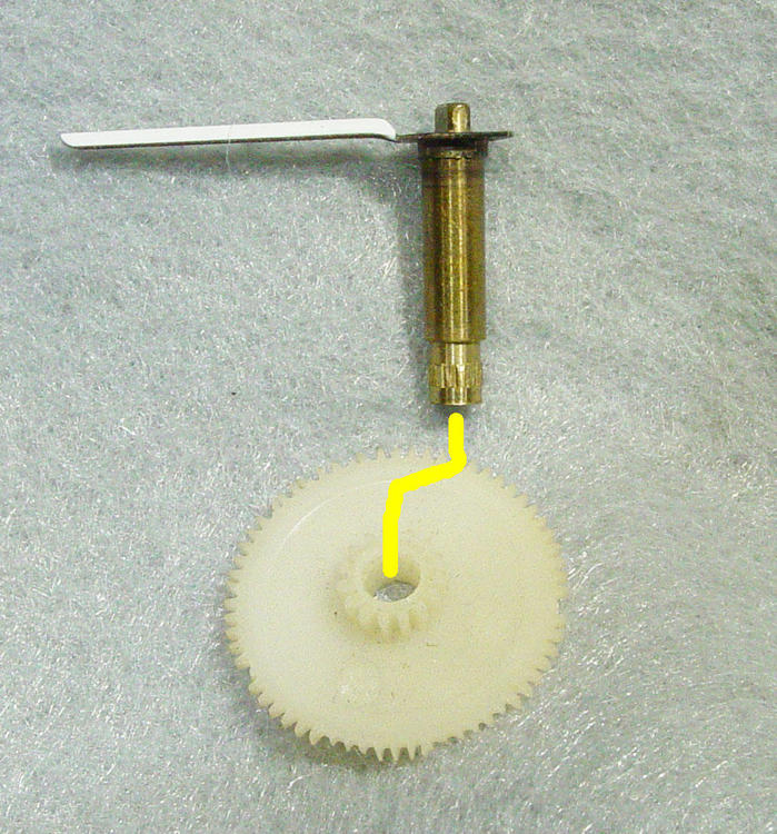
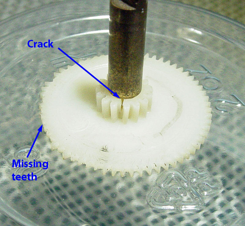
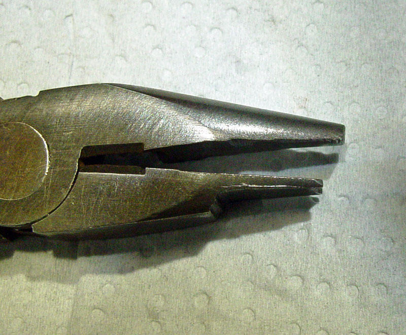
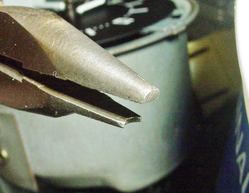
Ok I have to respond again to this comment on clock hand removal. Forks, spoons, and knives are not the correct tools for the job! You may be able to get the hands off, but at what cost. I know this may work for some, but using a fork/spoon can cause a big problem . This method can cause the clock stem to come out of the nylon main drive gear as pictured. In addition, this rocking motion of the clock stem back and forth can crack the brittle nylon gear which the stem is inserted. A gear puller pulls the clock hand up while pushing down on the clock stem and doesn't disturb the lower gear. Nylon gets brittle after 40 years and if you crack the smaller gear it distorts and will not mate correctly with the adjacent gear. This is what caused the pictured gear to fail. The cracked gear locked up the mating gear and the pressure applied by the owner to set the clock time stripped several teeth from the main drive gear .There are many types of gear pullers and I have a several , but the size of my hands make it difficult for me to use so I made my own. It only tool me 10 minutes on a small grinder to make this tool. Also, cardboard is not the material you should be using against the very delicate paint on the clock face. This is uber fine very porous flat paint. What I have found best and doesn't scratch is VIVA cloth towels. This also prevents hand oils from staining the paint which is extremely hard to remove. Never use any solvents , water or IPA( isopropyl alcohol) on the clock face. Kanto Seiki changed the white paint formula over the years and it may smear with water or IPA. I hope this helps. Ron
-
The clock only "ticks" every 5 seconds and doesn't sound like you have a problem, now. However, these clocks are 40 + years old and parts ware out. If your clock is slow that's the first sign that it needs repair.
-
I forgot to mention that if you pull on the clock hands hard enough you can pull the clock stem out of the main gear. The brass stem is knurled at end and is hard to put back in the original position. If not exactly positioned the interference fit is more than the nylon can take, due to age, and can crack the smaller gear. Just a heads up! NOTE: This only applies to the 280- analog quartz clocks.

-
Thanks. I have seen that in the past and wondered what it was. This will narrow down the search.
-
I can't find the ones I have stashed away , but did call in a favor. I should have one sometime next week. I do have a jumper harness extension for testing the tachometers in my car. Now if I can just find the harness!!
-
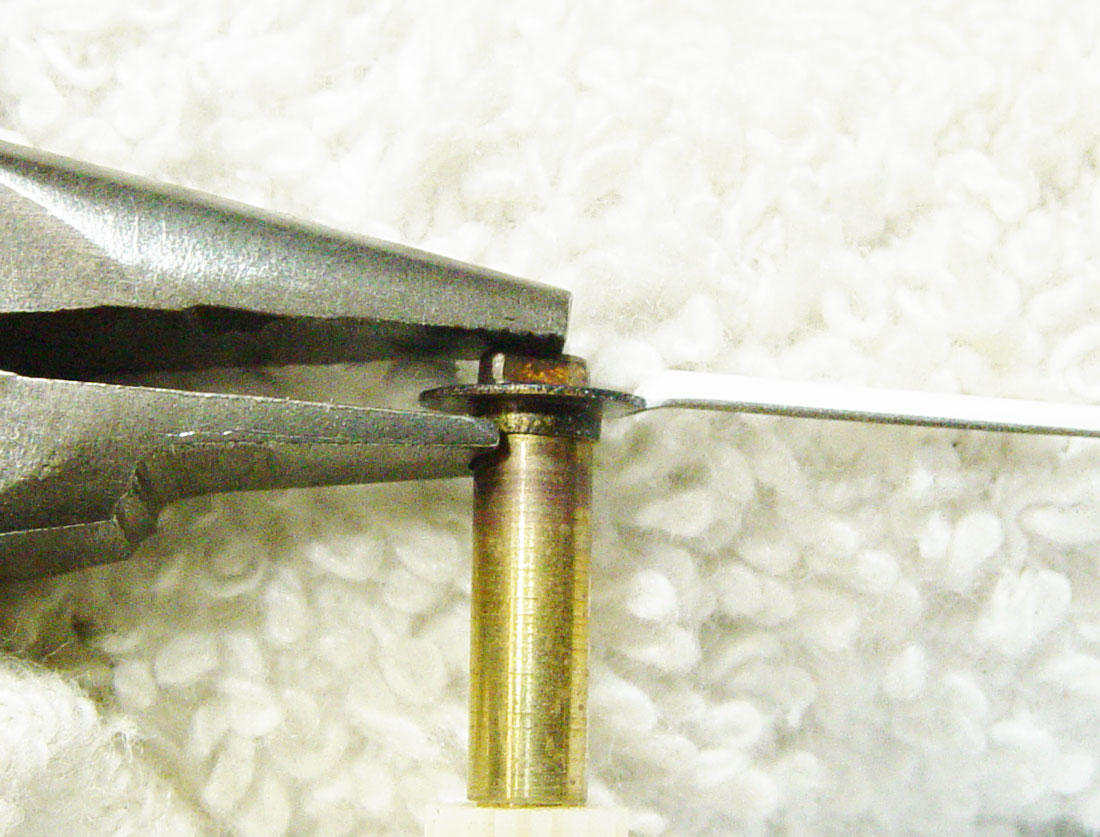
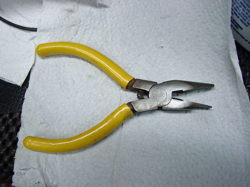
What I use is a home built puller. Well, it doesn't pull , but breaks loose the corrosion between the brass shaft and the tin clock hand. You have to be very careful and not touch the clock face as that will cause damage. If you look at CH-4 photo you will see that the pliers contacts the shaft just below the flange of the hand. Apply a small amount of pressure by squeezing the pliers. Do this again 180 deg from your first contact. What you want to do again is break the corrosion contact between the clock stem and the hand. Once the hand starts to move stop and use your finger nails to remove the clock hand. If you try and do this all in one step you will bend the large flange of the clock hand. Also, I use a soft paper towel that goes around the clock stem so the clock face is protected from finger oil and also protects the face from pliers contact. Let me know if you have any questions.

-
I currently don't have a test bed to check the tach. as the injection system is off my car. First I would need to see a schematic to see what is going on and second you have a different set up than my stock 280. I've converted several of the 240-280 swaps and each was different on how the owner got the tach to work.I do recall that some had to add a 1 to 5 k resistor in line with the coil to get the tach to work. Each after market system has slightly different requirements from 240 to 280. I can appreciate you wanting to minimize the pain of installation, but there needs to be more homework done before blindly trying to get this to work. I have a tach somewhere and when I find it I can make a schematic. The more I see that video of the "5 ohm" resister removal/jump the more questions I have.
-
I'm with you all the way Captain. I know I had a schematic of the 280 Tach , but can't find it. Curiosity has the best of me and I went back and looked at the U-tube of the mod on the 5 ohm resistor. I can't be 100% positive , but what I see is a 22k resistor that was shorted by the jumper. That would make a lot more sense that eliminating a 5 ohm resistor and the tack started working. I also didn't realize that there was a resistor in line on the 280 tach . I pulled my 75 schematic and it shows the resistor , but no value. Now I'm going to have get under the dash and locate that elusive resistor.
-
Pull the hatch lock and key you want to use to a lock smith and have them re-key it.
-
This is anything but a normal virus.
-
Information is available . The fact is most don't believe it. The fact is that contact with infected people is how this virus has spread all over the globe. Facts: Covid -19 is a protein and not a normal virus. The lipid, fat layer, that protects it is what has caused all the problems. The normal body immune system can not remove this fat layer and the virus attracts the DNA shutting down what immune system the body has. Currently there is no cure for those infected and the only recourse is to limit those being infected ie: stay away from groups of people. It's not know why some have recovered from the symptoms of the virus of if they can become re-infected again. Thank god most stores here are requiring masks or you can't enter . Why people are going out in public without masks or gloves is beyond me. Protect yourselves because the stupid will infect the rest and prolong the problem.
-
View Advert 75-76 280z clock For sale is a completely refurbished OEM 280z clock that keeps excellent time. Update: the clock is really keeping excellent time and needs a good home. Clock is correct for the 75 and 76 280z. If interested please PM or I can be reached at: ron@zclocks.com Price is $179 + ship Thanks for looking and be safe. Advertiser zclocks Date 04/07/2020 Price $179.00 Category Parts for Sale
-
I wondered when the topic of guns would come up and I guess I'm not surprised. Growing up and was always around guns and taught that is was a great responsibility and not to be abused. I live in the great Anitgun state and it's like living behind enemy lines. This is an article I picked up several years ago that was written by a Maj in the USMC. on why "Carrying A Gun is a civilized act" The Gun Is Civilization" by Maj. L. Caudill, USMC (Ret). Human beings only have two ways to deal with one another: reason and force. If you want me to do something for you, you have a choice of either convincing me via argument, or force me to do your bidding under threat of force. Every human interaction falls into one of those two categories, without exception. Reason or force, that's it. In a truly moral and civilized society, people exclusively interact through persuasion. Force has no place as a valid method of social interaction and the only thing that removes force from the menu is the personal firearm, as paradoxical as it may sound to some. When I carry a gun, you cannot deal with me by force. You have to use reason and try to persuade me, because I have a way to negate your threat or employment of force. The gun is the only personal weapon that puts a 100-pound woman on equal footing with a 220-pound mugger, a 75-year old retiree on equal footing with a 19-year old gang banger, and a single guy on equal footing with a carload of drunken guys with baseball bats. The gun removes the disparity in physical strength, size, or numbers between a potential attacker and a defender. There are plenty of people who consider the gun as the source of bad force equations. These are the people who think that we'd be more civilized if all guns were removed from society, because a firearm makes it easier for a [armed] mugger to do his job. That, of course, is only true if the mugger's potential victims are mostly disarmed either by choice or by legislative fiat--it has no validity when most of a mugger's potential marks are armed. People who argue for the banning of arms ask for automatic rule by the young, the strong, and the many, and that's the exact opposite of a civilized society. A mugger, even an armed one, can only make a successful living in a society where the state has granted him a force monopoly. Then there's the argument that the gun makes confrontations lethal that otherwise would only result in injury. This argument is fallacious in several ways. Without guns involved, confrontations are won by the physically superior party inflicting overwhelming injury on the loser. People who think that fists, bats, sticks, or stones don't constitute lethal force, watch too much TV, where people take beatings and come out of it with a bloody lip at worst. The fact that the gun makes lethal force easier works solely in favor of the weaker defender, not the stronger attacker. If both are armed, the field is level. The gun is the only weapon that's as lethal in the hands of an octogenarian as it is in the hands of a weight lifter. It simply wouldn't work as well as a force equalizer if it wasn't both lethal and easily employable. When I carry a gun, I don't do so because I am looking for a fight, but because I'm looking to be left alone. The gun at my side means that I cannot be forced, only persuaded. I don't carry it because I'm afraid, but because it enables me to be unafraid. It doesn't limit the actions of those who would interact with me through reason, only the actions of those who would do so by force. It removes force from the equation... and that's why carrying a gun is a civilized act. By Maj. L. Caudill USMC (Ret.)
-
Thanks Mike appreciate the good words. Ron
-
Steve , You will have to get another car so I can populate it with a clock..
-
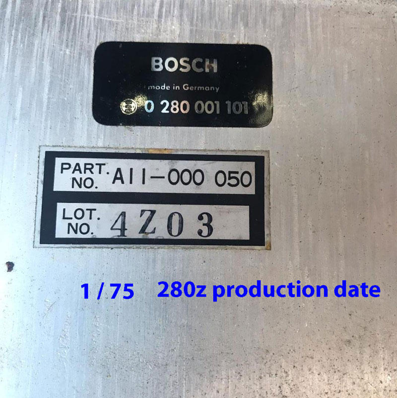
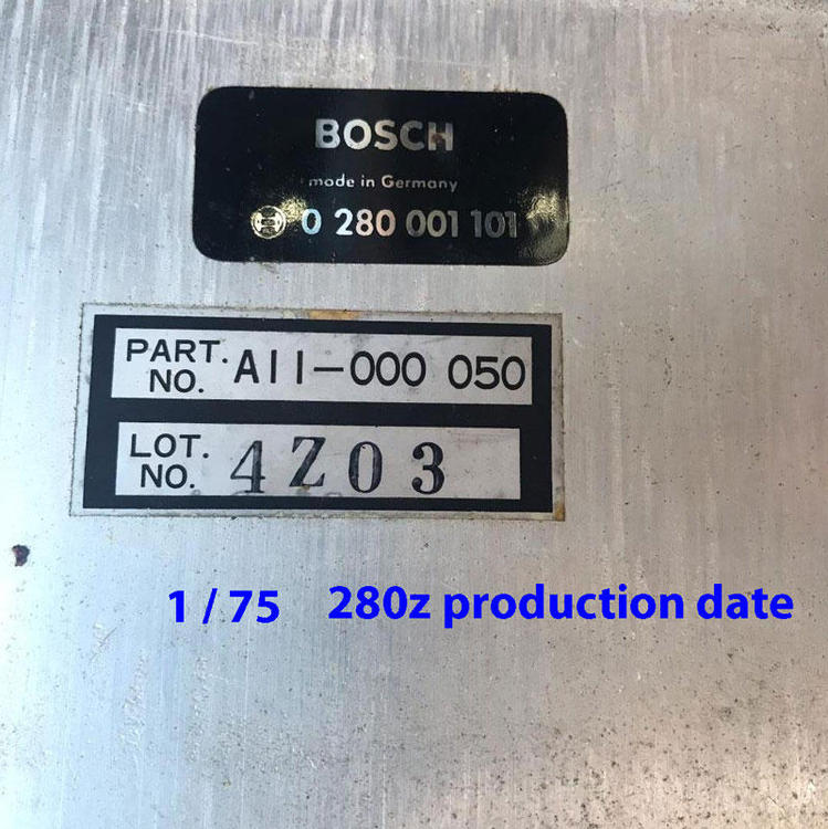
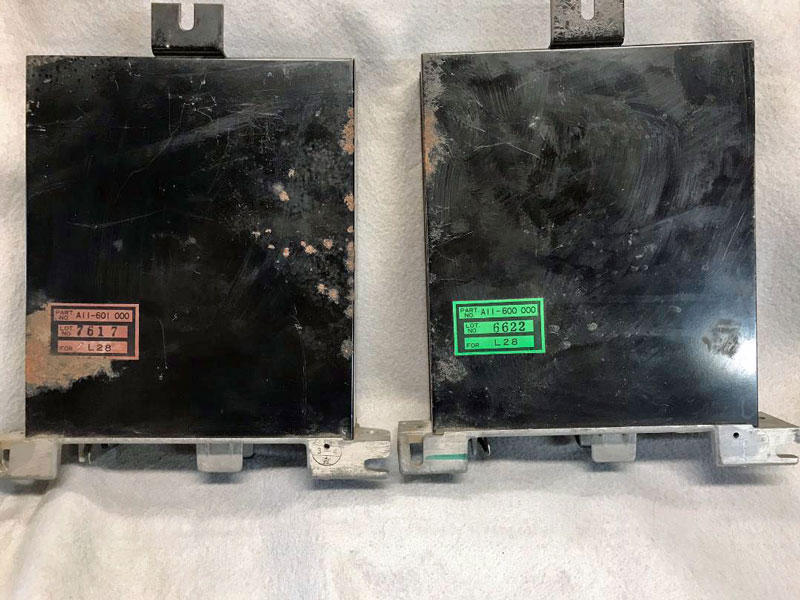
Very interesting topic. I have a 1/75 280z with CPU PN A11-000 050 which doesn't show up on the Federal or CA models chart. My car was a CA car from the beginning and has a M/T. I have two additional CPU's I grabbed several years ago when gong through wrecking yards. I don't remember what years they came out of, but here's the curious thing. Both of the CPU's work perfectly in my car. That is the car starts and runs just as good as the OEM BOSCH CPU . Just thought I would add to mix. Ron
-
View Advert 280z clock, OEM refurbished For Sale is a completely refurbished OEM clock (not Quartz) that is correct for the 77-78 280z. The circuit board was rebuilt, mechanism cleaned , lamp replaced, lens highly polished, and the housing/ bracket bead blasted and clear coated. This clock has been keeping excellent time for the last month and an excellent choice for a daily driver or full up resto. Cost is $179 US and free shipping within US. If you have questions please PM or email ron@zclocks.com Advertiser zclocks Date 02/12/2020 Price $179.00 Category Parts for Sale
-
View Advert Wanted: analog quartz clocks If you have an analog quartz clock for sale from 77-83 please contact me at: ron@zclocks.com or PM me. Advertiser zclocks Date 02/09/2020 Price Category Parts Wanted Year 77 Model 280
-
Hope you all will take a look and interested in what you think. The entire site was upgraded to: * Be secure * Cell phone compatible * User friendly * Faster loading I still have a few bugs to work out , but happy with it so far. Ron(Zclocks) zclocks.com
.jpg.9830ecbbfc082638e37c9f547f8e9a87.jpg)
.jpg.3ce2245362b35505f7fe8fc66af76cec.jpg)