


240260280z
Free Member
-
Joined
-
Last visited
Everything posted by 240260280z
-

-
Delta thinks it is the springs since they are the common part and that the break in process was correct yet the cams did not service the break in periods. They recommend I use only one of the Schneider valve springs for the next break in. I'll put a stock cam, springs and related components in to get to the ZCON.
-
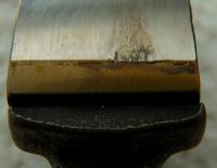
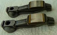
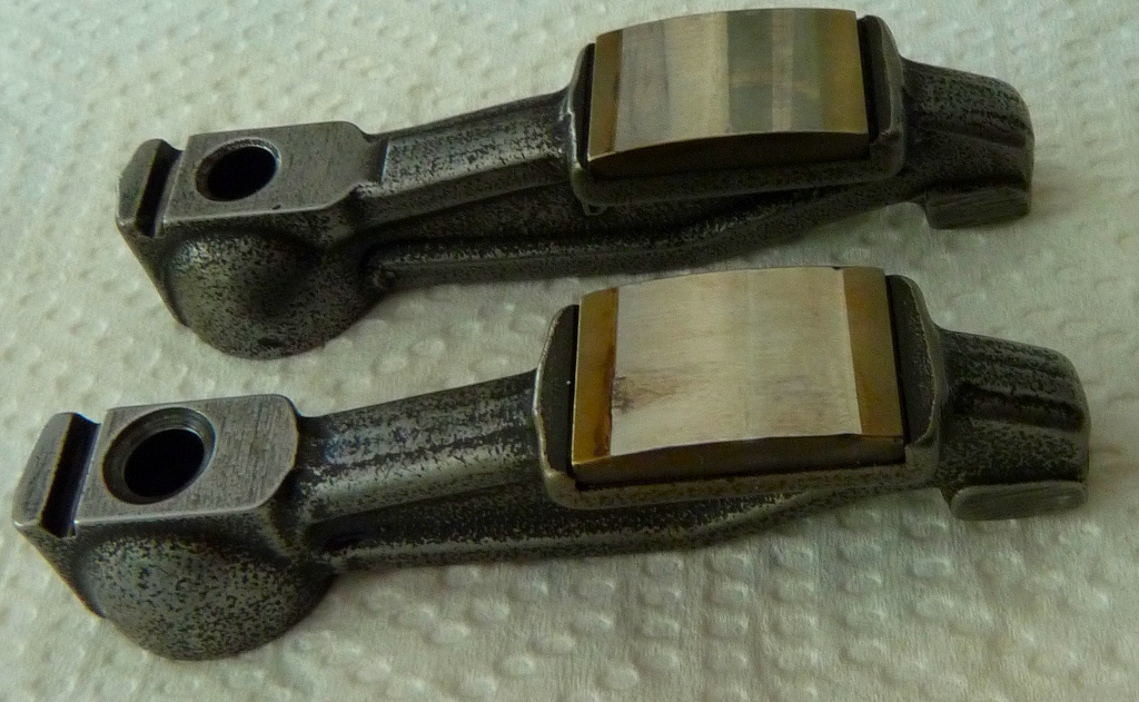
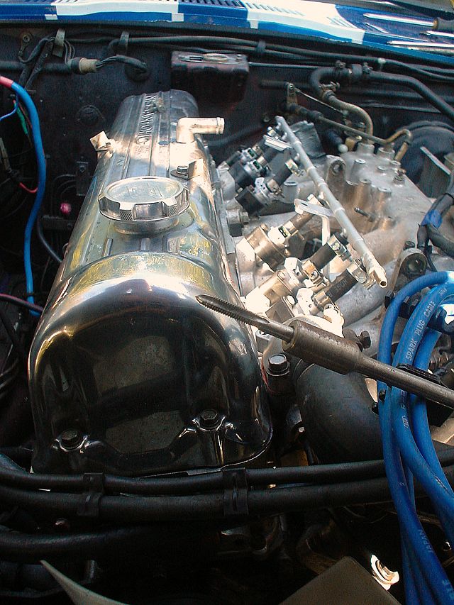
Thanks Guy, I'll ring delta. Here are photos of the rocker from #1 Exhaust corresponding to the worn cam lobe. I also pulled off #1 Intake to compare. Both have good wipe patterns. I notice a ridge on the plug side of the pattern on both rockers. It is easily felt with a finger nail and can be seen. It is more noticeable on the worn one. There is no ridge noticeable on the distributor side of the wipe patterns. So it seems there is more wear on the valve return portion of the cam's cycle. I also observed great oil flow after cranking but it seemed longer than normal for it to appear. Any ideas if there is anything related to this? Only Purolator and Wix filters were used since new. The rockers in the photo are Delta regrinds. I have other used stock Nissan rockers i can throw in if that may be the culprit. Yes/No???
-
-
Here is an economical DIY way. Parts: - 3 rod ends (match thread to the holes on your manifold) make sure you have the right eye hole diameter for the rod - 1 rod - 4 door hinges (to replicate cannon lever arms) - bicycle cable assembly - hardware Work: - install 3 rod ends - install rod - separate door hinges, bend door hinge (one side with two pin holes) and drill holes for rod ends, install on rods and fasten with hardware - fabricate a push rod with rotating ends and connect to the carb arm and the lever arm OR 4 bicycle cables: 1 to each carb with the other ends tied to the same small rectangular bar. The forth bicycle cable connects the center of the bar to the accelerator cable. You will need to design and develop the end hardware and stand offs to make it work. (you may be able to use small wheels as pulleys too.
-
I just tried the choke on triple DCOE 40 151's with the default choke jets/tubes/air that came with the car. It seems to be too rich and no fast idle. Can someone describe how 3weber chokes are supposed to behave when properly set up? What will the idle jump up to when engaged? What A/F should I aim for? Thanks
-
-
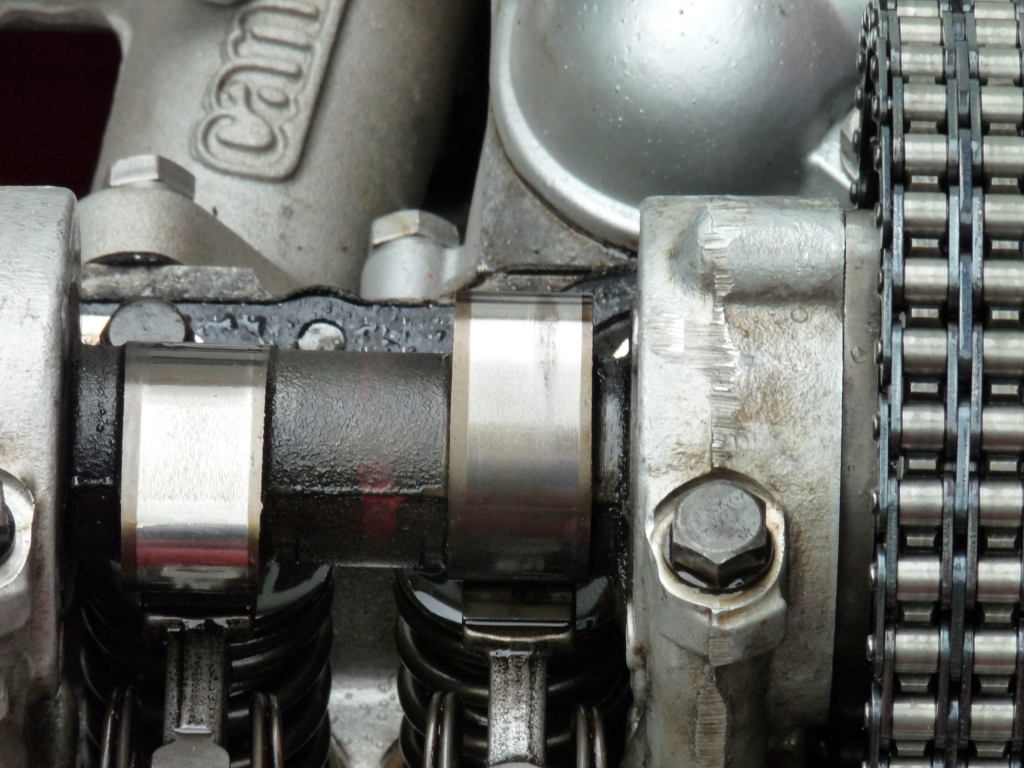
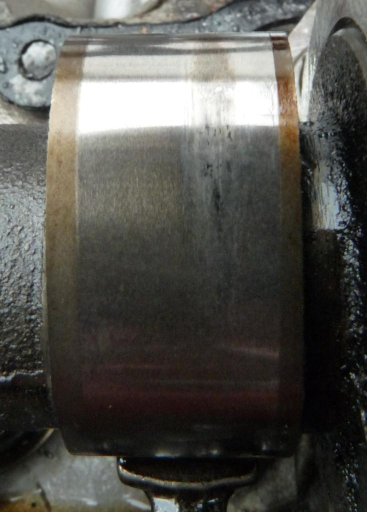
L24 fresh rebuild with Schneider springs, medium Delta regrind Cam (internal oiling), and new reground rockers ate the cam after ~ 2000mi. Very good oil pressure. Assumed bad metal, straight 30 break in oil followed by synthetic oil played a part. After removing and resolving the above... A new medium Schneider Cam with new rockers was installed 1,500mi ago and lobe 1 is starting to show wear. (on the back side of the lobe). The oil is dyno with zinc additive. I am now guessing that the Schneider springs and/or a partial oil blockage to the head are to blame. The springs were extremely difficult to install due to their high spring constant and the oil flow out of the cam when cranking using a remote starter seems less than the old spray bar that I have seen many times. Any ideas? My current plan of action is: 1. Try a new oil pump and crank with starter to see if oil flow improves. 2. If no improvement then take off the head: - inspect oils passages in head - clean and inspect contents in oil galley between filter and oil restrictor in top of block - install regular springs and a Nissan Cam with Nissan Rockers. This car is going to NH next week so no time to mess around. All help, advice most welcome.
-
Here is a quick run through of the geometry: T/C rods adjust caster (the front to back tilt of the Strut) Tie Rod ends adjust toe. (how parallel front wheels are to each other....the fronts can point in or out or not at all) Camber is how the tops of each wheel tilt (in towards the car, or out away from the car, or not at all)
-
Sad news. Strange problem. What does the oil filter contents look like? Open it up and have a look. I can only guess that something in the filter went down stream and blocked the main passage to the bearings.
-
See you there. Got the hotel booked but not registered yet. Arriving Sunday.
-
Back at the Webers and learning more and more. Here are a few more tips: 1. The axis of the long rod running across the manifold should intersect the hole in the fire wall bracket where the shepherd hook loosely fits. Adjust the three heim joint heights so that they are all the same and inline with the fire wall bracket's hole (like in the photo below). heim joint Shepherd rod inline with rod 2. The hole you choose on the rod-arm determines the throw and mechanical advantage. The rod-arm is a lever and the further out the adjustable-arm is connected, the harder it is to press the pedal but the less pedal travel is needed. The distance "A' in the drawing below represents the selected rod-arm hole to the rod distance. Most seem to use the furthest hole at the end of the rod-arm, like this (look at left side of left most carb): Rod Arm Connected at Furthest Hole ..... but the weber drawing below seems to indicate that "A" is slightly longer than "C" (C is ~37mm on the 151 DCOE 151's I am working on). I have the cannon part below. The hole distance to the rod hole (on centers) are: end hole: 60mm middle hole: 47mm inside hole: 35mm Presently, the car I am working on is set at 60mm and the DCOE has the common problem of not fully returning to idle stops. I plan to increase the return to idle force by using external springs so I will need more mechanical advantage to overcome these new springs. I will try the 35mm hole first to get more mechanical advantage and have a further foot travel then move to 47mm for experimentation. More foot travel should provide finer control of the throttle and hopefully not too much so as to be unnatural or tiring. 3. The other detail in the weber drawing is that "A" is parallel to "C". The adjustable-arm should be adjusted so as to make "A" parallel to "C". All three adjustable-arms should be set to the same length. An easy way to do this is to clamp two parallel bolts in a vice and place each adjustable-arm on the bolts one at a time to be the same distance. 4. Try to ensure that the rod-arm is directly above the corresponding arm on the carb. Ensure nothing binds or rubs. 5. Set the accelerator pedal stop (on the floor under the pedal) so that it prevents the foot pedal from over torquing the weber throttle plates and twisting the shafts.
-
BAD NEWS: I bought these from Pierce back in April and had them shipped to where the triple webers were. I finally drove the 600km to re-tune the Webers and the springs sent were the wrong ones.... shorter and thin....i.e. weaker. This was disappointing. Try Spruell Motorsports as mentioned above.
-
yes Jan, just flare the ends.
-
yeah, I think their site got poisoned.
-
yes it works fine...since 2006. If I were to do it again I would just flare the tube ends rather than braze. I think I just used a hack saw.
-
Tbone... could you please post the details in the articles section of this web site? I get a malware warning at Hybridz and it would help many others.
-
back near the firewall. did this experiment for fun in 2006
-
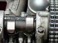
Absolutely correct but there is one more detail: the chain should initially be installed with 0 slack. the tensioner simply maintains a firm pressure and takes up slop over time as the guides wear and the chain stretches. Here is the initial install with no slack:
Is there a diy kit somewhere?
You can get details on US versions by looking in Factory Service Manuals front and rear suspension sections here: XenonS30 Some info here: http://atlanticz.ca/zclub/techtips/springs/index.html
http://vimeo.com/16029980
This is a start: https://www.google.com/search?num=100&newwindow=1&q=euro+spec+site%3Aclassiczcars.com&oq=euro+spec+site%3Aclassiczcars.com&gs_l=serp.3...58533.63602.0.65119.9.9.0.0.0.1.142.748.7j2.9.0....0.0..1c.1.20.serp.D8xAEXTiZa4 https://www.google.com/search?num=100&newwindow=1&q=alan+hs30-h+site%3Aclassiczcars.com&oq=alan+hs30-h+site%3Aclassiczcars.com&gs_l=serp.12...24245.31075.0.33843.11.9.2.0.0.0.71.558.9.9.0....0.0..1c.1.20.serp.HkRI1NB17rw
dang that is a bummer Jim....good thing you were there to resolve it. I wonder if there are marks on the inside of the valve cover that indicates the loose chain?

Important Information
By using this site, you agree to our Privacy Policy and Guidelines. We have placed cookies on your device to help make this website better. You can adjust your cookie settings, otherwise we'll assume you're okay to continue.