240260280z
Free Member
-
Joined
-
Last visited
Everything posted by 240260280z
-
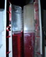
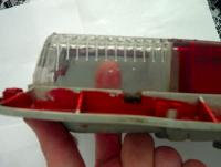
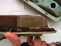
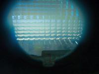
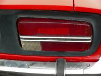
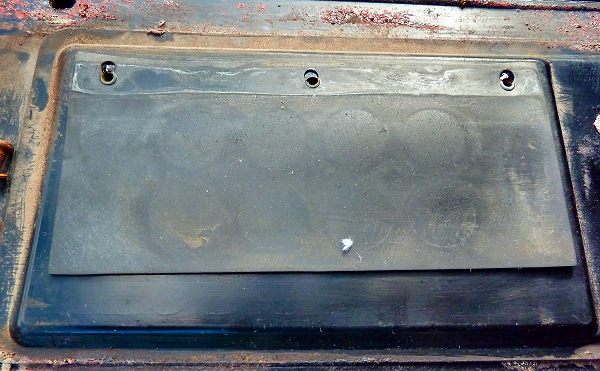
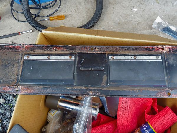
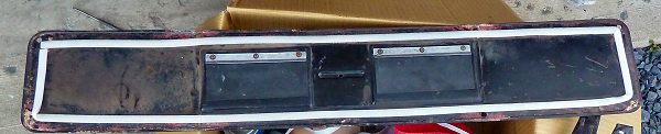
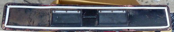
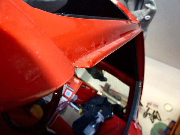
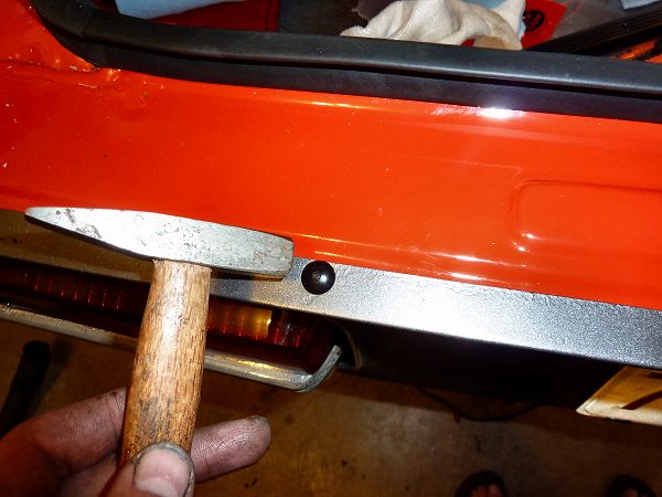
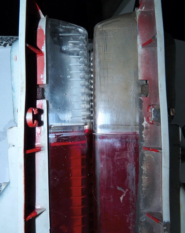
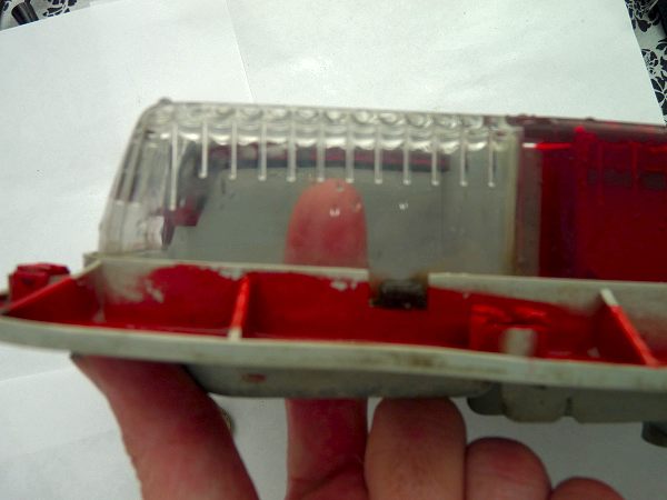
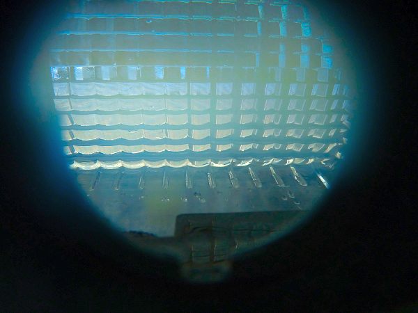
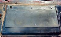
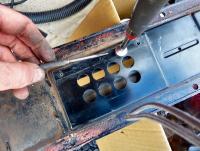
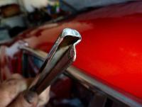
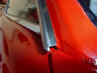
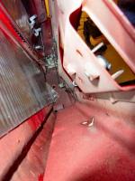
 Jan 1971 240z. I decided to refresh the stock vent system and at the same time, bag the interior so that all possible leaks were sealed. I used a thick vapor barrier from the home insulation industry as well as a special sealing tape to close all holes (grommets,rust holes, panel holes, empty bolt holes) and panels from front to back. Here is what I did to refresh the vent in the hatch: The original hatch had long lost the perimeter seal. It was just globs of an seemingly old acrylic caulking or a decayed foam seal that was similar to globs of chewing gum. [*=1]The two rubber flaps that blow outward when air flows through the cabin were settled into a permanently open "lifted"position. The chance they would ever close under negative cabin pressure seemed unlikely in this state. [*=1]To refresh the rubber, I cleaned it and flexed it then wiped with lacquer thinner. To make the rubber seal better, I flipped around so that the default shape now pressed against the panel. [*=1]Taking the screws out makes reassembly a bit challenging. My solution was to use a magnet to lift the steel bar (tapped with 3 holes) up to the inside (relative to car) side of the vent. I then used a scribe to adjust the steel bar so that the holes aligned. This then allowed the screws to attach. Note that there is one short screw and it goes closest to the centre of the panel. Actually the procedure is a little more complex: the first step is to get a screw into the middle of the bar then to get a screw, rubber seal, and top metal plate into an end hole. [*=1]Here is are the two refreshed flaps in place. [*=1]To seal the panel, I ran a closed cell foam around the perimeter and I also ran a bead of sealant around the perimeter to completely seal the panel against the hatch.


-
Congrats! Sounds like a great time was had.
-
Very happy to help! It was great talking... your enthusiasm and energy to beat the problem is inspiring. If you need anything else I'll be glad to help.
-
Looks great..... and s/n 333 wow! That is an early bird.
-
Thanks! Always learning on this site.
-
Nope,,,, 12 to 16 hour days resto for 9 day week.... no time for that unfortunately.
-
You have to bite the bullet and learn how these carbs function if you are going to tune them, haphazardly turning a screw to a jet will not help if your problem is elsewhere.
-
I forgot to say "Never use your dishwasher as a parts washer".... maybe a used one out in the garage with a recycled solvent such as varsol or better, some orange based solvent or simple green but it may exploded or the plastic melt with a volatile solvent. Could be an interesting "Mythbusters" experiment.... I just head of a used washing machine and a couple of boards with nails being used as an apple cider shredder/press.
-
yes. For sure, never use anything from your kitchen that you will reuse. Use the new one in you kitchen and use the old one for your car... btw it is Thanksgiving in Canada this weekend so it would go down particularly bad there if you took the baster. You will get a kick out of this post: http://www.classiczcars.com/forums/showthread.php?43149-Kitchen-Duty-Tools-for-cleaning-(typically-carbs)-with-solvents-and-staying-clean.&highlight=kitchen
-
Use a turkey baster to draw the fluid from the reservoir. Top up the reservoir with new fluid. loosen the rear left brake bleeder and hook a clear drain tube to it and into an old container (oil, washer fluid, etc) Pump the brake pedal to flush the old fluid out. Keep topping up the reservoir. Watch the colour of the drain tube... when you see clear fluid, close the bleeder. Move to rear right then hook up bleeding tube and pump fluid through until it is clear. Closeup then move to front right then front left. Finish the job by bleeding/flushing the clutch line. Have a friend rather than wife or gf do the pumping.
-
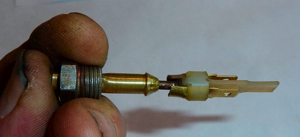
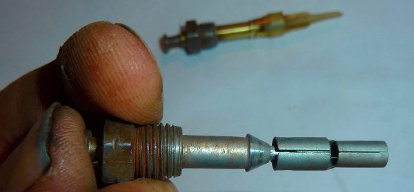
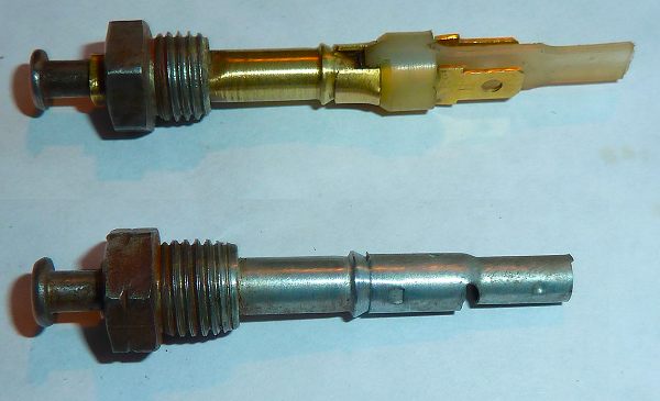
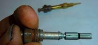
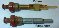
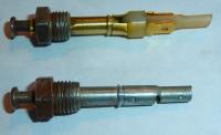
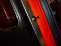
The switch functions by simply grounding the circuit(s) when the door opens. In USA cars, the driver side switch has two connections for grounding two circuits: 1. Dome lamp 2. Door-open-with-keys-in buzzer The passenger side switch has only one connection for grounding the dome light. Note: there are wires in the USA harness that are tucked away and not used that are for a "step light" ( a light in the door when it is open). Looks like a very creative brake line fitting adaptation to me Here are the switches after a refresh with an abrasive. This is the normally "open" state for the driver side switch when the door is closed and presses on it. This is the normally "open" state for the passenger switch when the door is closed and presses on it.
-
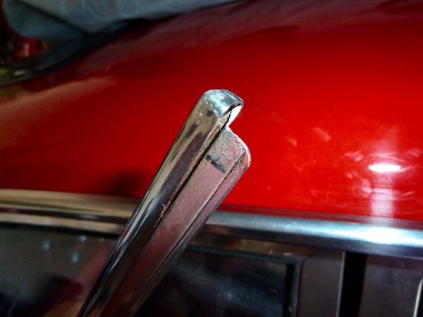
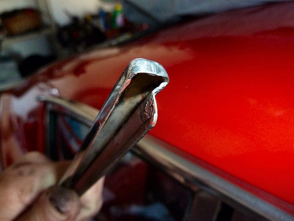
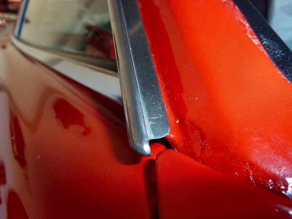
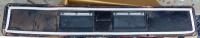
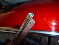
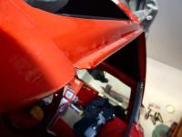
Some photos for reference. For installing and removing simply pick an end then start rolling with fingers. I found that removing works best starting from the rear and installing works best starting from the front. They clean up well with fine steel wool. *****Addendum by Enrique Scanlo ****** Excellent post. A couple of notes to add, having done a few of these. Sometimes due to grime and other schmootz that creeps in underneath, you'll need more help than simply rolling the trim with your fingers. In that case, use a flexible scraper to GENTLY ease the lower edge out from underneath the drip rail. Once it begins slipping off, don't get too over eager in twisting it off as this can cause you to give it a fixed twist that could cause you to kink it. Even after removing it, it may have a bit of a twist on it. DO NOT TRY TO STRAIGHTEN IT OFF THE CAR. If the twist is just a gentle curve, it will go away once you replace it on the car. I've seen perfectly straight trims get mangled because someone tried to "straighten it back to shape", and trims that seemed corkscrewed out of shape go back on perfectly well. Personally, I wouldn't use steel wool on the trim unless it was severely scratched and gouged, and then I would take it very slowly. I prefer some of the metal polishes on a rag after cleaning with lacquer thinner. But, your experience with the steel wool or polishes will be the deciding factor. Again, excellent post Blue. I'm promoting this to another excellent Technical Article by Blue. Enrique Scanlon Moderator
-
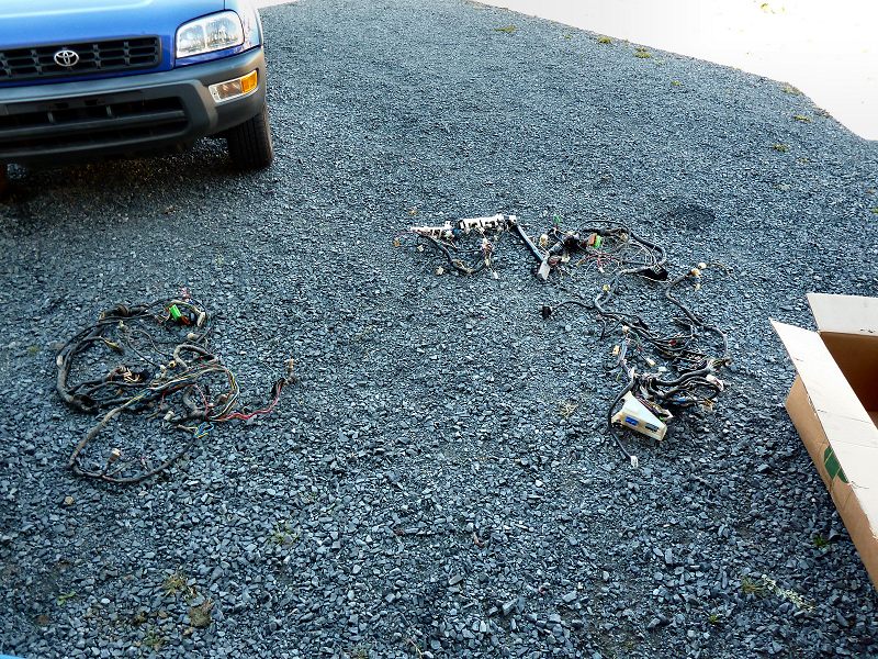
I figured I'd share some photos of the resto:

-
The two things to balance are: 1. Air into engine 2. Fuel mix with air For number 1 you have to adjust the throttle plate and linkage For number 2 you adjust jet depth Here are some links to help. If you want to be walked through it, just send me a personal message with your phone number and a time to call and I'll ring you. http://www.classiczcars.com/forums/showthread.php?41940-Quick-and-dirty-SU-Tuning http://www.classiczcars.com/forums/showthread.php?43214-Balancing-SU-Suction-Pistons-and-matching-fall-rates http://www.classiczcars.com/forums/showthread.php?43182-Early-240z-SU-Carb-Parts-List-and-Exploded-Diagram http://www.classiczcars.com/forums/showthread.php?43176-SU-Reassembly-Step-by-Step-Part-1-Tear-Down-Torn-n-Tattered-Worse-for-Wear-n-Tear&p=376281#post376281
-
Hmmm I just retried it and it worked fine. Is it the version of excel that is causing the problem?
-
Great! I'll try that when I do a smoke test Thanks again! What's the count? I owe you a lot.
-
Thanks a million! That helps immensely! "Steve you are a star." (as they say in Ireland).
-
I ran two strips of peel and seal inside the door panel. I figured the vapor barrier would keep the smell out. It made a noticeable difference in the "tap" test. I forgot to do the right side door before installing the window mechanism, however, I easily installed it afterwords simply with the window rolled up.
-
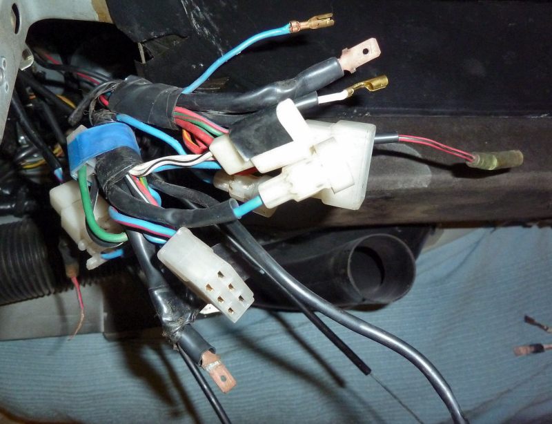
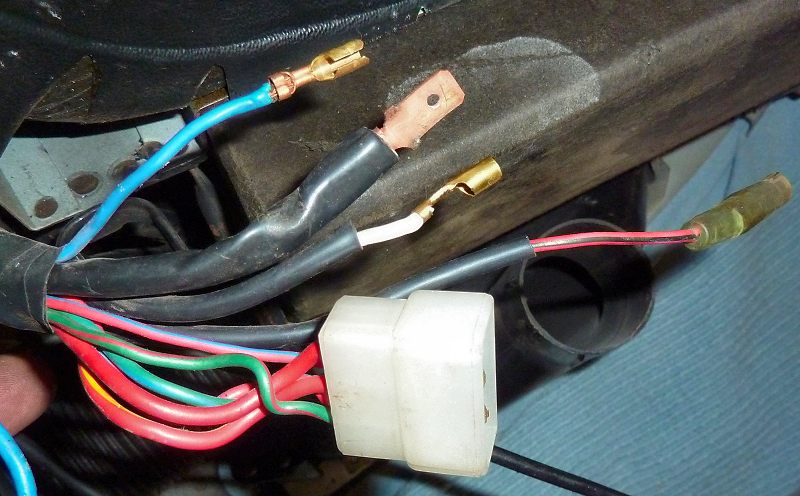
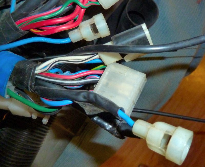
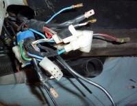
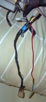
Here is the wire bundle coming out of the centre of the dash on a 1971 240z: Here is one part of the bundle: Q, what do the blue, white and red-with-blk-stripe connect to? Here is the other part of the bundle: Q, what do the blue fused leads and the connector with the blue, white and white-with-blk-stripe connect to?

-
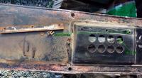
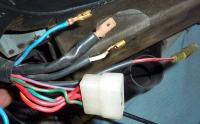
In the photo below (1971 240z Jan.), there are two separate leads with barrel connectors coming from each side of the fuse box. What do they connect to?
-
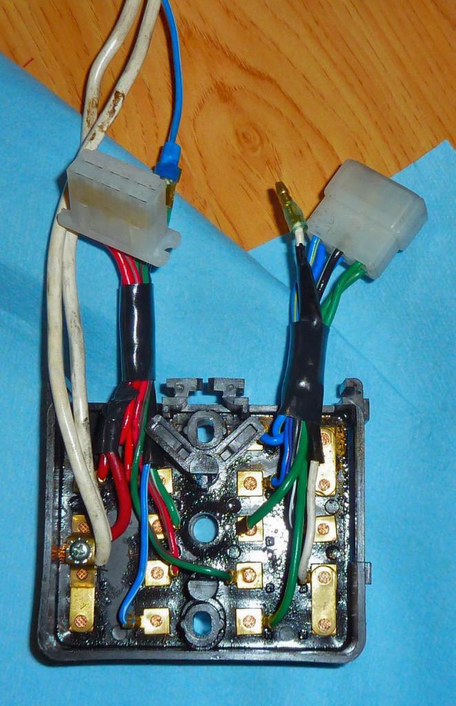
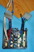
Just a quick sanity check on harness 27155-e4400: In the photo below: 1. The black ground is obviously tied to chassis ground at the top of the photo. 2. The top 6 pin connector plugs into the back of the fan switch. 3. The bottom 6 pin connector plugs into the blower assembly. Questions: 4. but where does the red power cable with inline fuse plug in/ draw power from? 5. and what about the 3 pin connector tied back at the top? Is it for AC option?
-
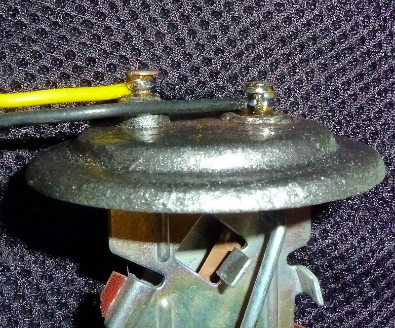
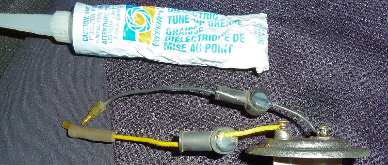
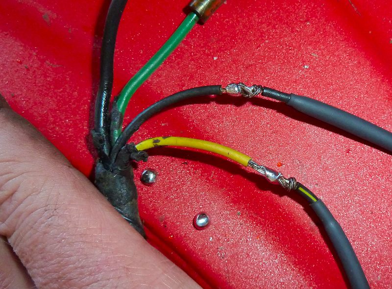
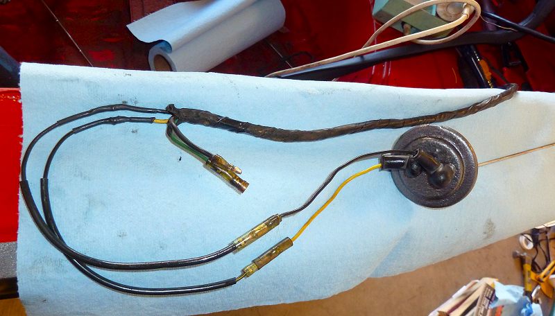
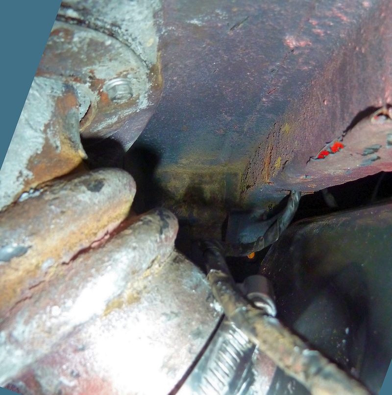
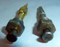
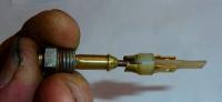
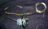
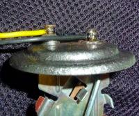
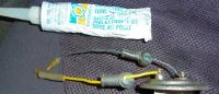
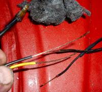
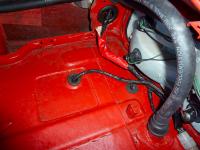
71 240z resto had bare corroded wires where the fuel sender connectors were supposed to be. Here is the quick and dirty solution: Step 1: Pillage the 280z 2+2 wiring harness that I bought from Jim Karst many moons ago (THANKS JIM) Step 2: Prepare to solder. Here are the pillaged parts: - black wire with bullet connector - yellow wire with bullet connector - rubber boots for the solder tails Step 3: Solder the leads: note: - the yellow lead carries the voltage and attaches to the pin with the elevated stand off (insulator) - the black lead is the return and is at ground potential. (not insulated and connected to the metal cover) - when soldering; ensure that the pins are thoroughly scraped/sanded down to exposed shiny brass metal, as well; ensure that sufficient heat is applied to the grounded pin so that the solder flows well and no cold solder joint occurs. Step 4: Seal the boots with silicone Step 5: Solder a second set of new leads with bullet connectors to the wiring harness: In this photo, the new leads are on the right and the harness is on the left. I was unable to scavenge a yellow lead so I used a black with yellow tracer stripe. Step 6: The wires are now joined and soldered. Note the heat-shrink ready to be positioned. Step 7: The completed connections being tested. note: the bullet connectors at the harness are for the fuel pump. Step 8: The harness is now in position. I used the front deck grommet for the fuel leads and the back grommet for the rear ground lead. Step 9: The fuel sender leads come through the floor just behind the fuel sender neck. How the sender works: 1. 12V is applied to a b-imetal switch in the dash's fuel gauge then continues back to the gas tank via the yellow wire. 2. The fuel sender in the tank has a float that rises and falls with fuel level. As the float moves, it also changes the resistance in the circuit to the bi-metal heater. - The fixed side of the fuel sender's rheostat is connected to the yellow lead and is insulated - The variable side (wiper) of the fuel sender's rheostat is connected to the black lead and is grounded - As the float rises, the wiper effectively brings the ground closer to the yellow lead. This decreases the resistance in the bimetal circuit. This inturn causes quicker heating of the bi-metalstrip and pushes the indicator in the gauge towards the full side. - As the float falls, the wiper travels further from yellow lead. This increases the resistance in the bimetal circuit. This inturn causes slower heating of the bi-metalstrip and does not push the indicator as much thus the the gauge moves towards the empty side. 3. Resistance of fuel sender typically ranges from 10ohm to 80ohm (full/empty)


-
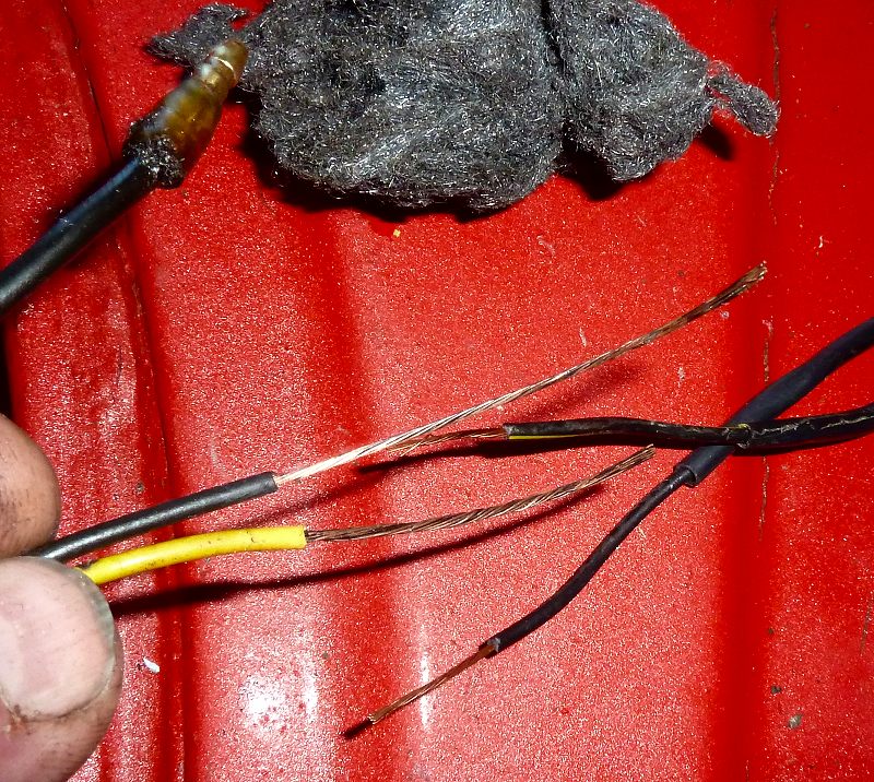
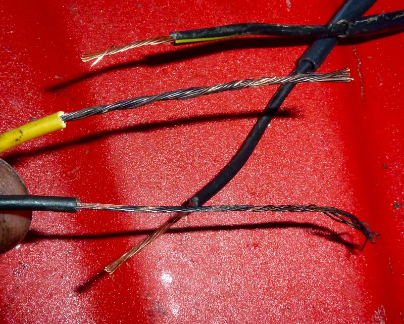
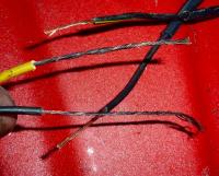
I was dealing with corrosion in the 40 year old harness at the fuel sender connector (lack thereof). When I removed insulation to expose copper, it was clear that moisture had entered the harness and seeped in. Rather than replace a large piece, I simply used steel wool to remove the corroded outer layer to expose copper that was suitable for soldering. Fortunatley the copper was not brittle and had a reasonably flexible core. Wires on left are the 240z harness leads to the fuel sender. The wires on the right and scavanged wires with connectors that I wish to connect to the harness. Note the different colours of the exposed copper. Here are the same wires after a little TLC from steel wool:

-
Time was the factor.
-
I removed all of the parts (except the spring clips that hold the plastic pins), soapy hot water, bathroom sink, artists paint brush (to reach in) and some swishing. 3M plastic polish on the outside and a nice refresh results.