


240260280z
Free Member
-
Joined
-
Last visited
Everything posted by 240260280z
-
 Thanks a million Jim ! I was just checking to see if any one answered and I saw no one had.... then as I back stepped I saw 1 reply. I'll route the harness then call it a night. 9:25pm here
 -
Hi, Can some one please run through the path for the rear wiring harness from the passenger foot well to the back. Where does it enter the passenger door sill ? 'i assume the big grommet goes where it enters the sill? Thanks
-
roflmao and my wife too koalia! we got the back hatch glass in today... tomorrow we will do the front... it really needs 3 people and no sticky sealant in the glass channel. The trick is to place the window rubber into the frame then pull th outer lip up onto the body before trying to pull the rope. the trim goes in easier before mounting the window but in my case, the seal was too floppy to hold it in. I will try to install the trim on the front tomorrow prior to mounting the window. My fingers hurt.
-
one of the 3 drag racing z's in out club...v8 in it http://www.facebook.com/video/video.php?v=2348022256269
-
excellent.... thanks
-
last few days degreasesed de-ziebarted all door internal assemblies disassembled and refreshed all lights/bulbs/sockets painted grill and rear tail light finishers installed taillights/finishers (all new ss hardware) degreased de-ziebartes de-sealanted all glass Fit rubber around all glass for 2 days to stretch and settle into shape Today: reassembled quarter windows restored passenger front turning light refreshed and installed passenger door mechanisms for glass,key, handle and locks refreshed and installed driver door mechanisms for handle and locks installed peel and seal in passenger door installed custom firewall insulator
-
ahhh I asked before I looked... there are two spaces in the seals... the outer is where the seal goes over the frame/body, the inner is where the seal goes over the pinch weld. I guess the outer gets the sealant and the inner gets the rope.
-
Are you losing coolant? (Level in rad dropping?) Pull plugs in morning then have a friend crank car and watch to see if drops of water come out of plug holes.
-
I have been reading posts and the fsm about the details of where and when to apply sealant and/or adhesive. The instructions and recommendations differ greatly. In fact some even say not to use sealant. Any guidance is most welcome. Here is what I presently plan to do: note: newly painted body and new seals Windshield: 1. Install weather stripping around glass. 2. lift front lip of weather stripping off glass and place a thin bead of sealant around perimeter. 3. Install cord in weather stripping 4. Install metal trim 5. Install assembly into window frame (pulling cord) 6. lift outer edge or weather stripping and apply a bead of sealant. Still up in the air: 1. Should I slobber everything with soapy water or windex or waterless hand soap... if so then will the sealant work well on top of this? 2. Should I apply sealant to the front of the pinch weld before seating the assembly? if so,won't the assembly and rope get messy? 3. Should I squirt a bead of sealant into the weather stripping channel before installing the glass? Thanks
-
ZT128 on this page: http://www.ztherapy.com/products/masterprices/master_price_list.htm
-
Ring me to talk. I'll pm my number
-
Nice wheels here but wrong bolt pattern: http://www.axiswheels.com/view-wheel-gallery/og-oldskool http://www.axiswheels.com/view-wheel-gallery/og-sakura http://www.axiswheels.com/view-wheel-gallery/ogsan
-
I am just getting to installing new seals. The MSA precision seal for hatch glass that came in the kit has a narrow opening for the trim. A second hatch glass seal that was mistakenly added to the kit as the inner hatch seal body seal actually has the wider opening for the trim. It now seems to match Arne's comment that PRC (precision) does both hatch glass seal types (wide and narrow)... but maybe the specs are for different retailers?
-
Part MSA PN PRC PN Cowl-to-Hood Seal 66321-E4100 Windshield Weatherstrip WCR-241 Door Frame Weatherstrip, LH 76802-N4600 49-8701 Door Frame Weatherstrip RH 76801-N4600 49-8712 Door to Fender Seal, LH 80931-N4501 Door to Fender Seal, RH 80932-N4501 Lower Door Seals (on door) 80935-E4101 Window Channel Weatherstrips 80335-N3700 49-8479 Window Channel Weatherstrip 80336-E8700 49-8554 Upper Corner Seal, LH 80934-N3400 Upper Corner Seal, RH 80933-N3400 Outer Quarter Glass Seal 76834-E4101 Inner Quarter Glass Seal 76836-E8200 Rear Window Weatherstrip 90305-E4100 Rear Deck Inner Weatherstrip 76912 N4500 Rear Deck Outer Top Seal 59-850 Rear Deck Outer Side Seals (both sides) 76911-N3000 280z Upper Door Seal, LH 80811-N4520 Upper Door Seal, RH (on door) 80810-N4520 Window Channel Weatherstrips, 80335-N4520 49-8480
It appears there was a mix up in the factory: I have incorrect weather stripping for inner hatch seal labeled 76912 N4500 from Precision (via MSA order) and a replacement with the correct part and same label 76912 N4500. The wrong part is actually the rear glass seal (now I have two). It is interesting because when I compare it against the one labeled correctly in the kit, the "wrong inner hatch seal" has a wider slot for the metal trim.
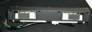
I measured the plastic rivets on a 71 240z rear finisher panel: 5mm or 3/16" 6 required.
B e a u t i f u l !
I have one but I'm hanging on to it.
It is a sad and big loss to all. I am grateful for all he has done. My condolences to his family and close friends.
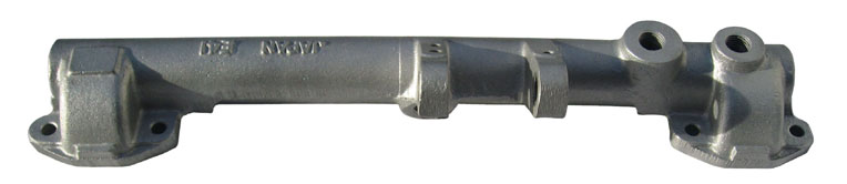
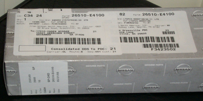
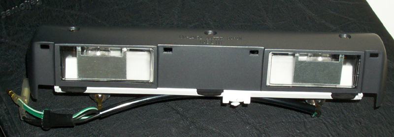
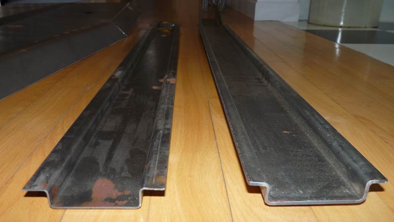
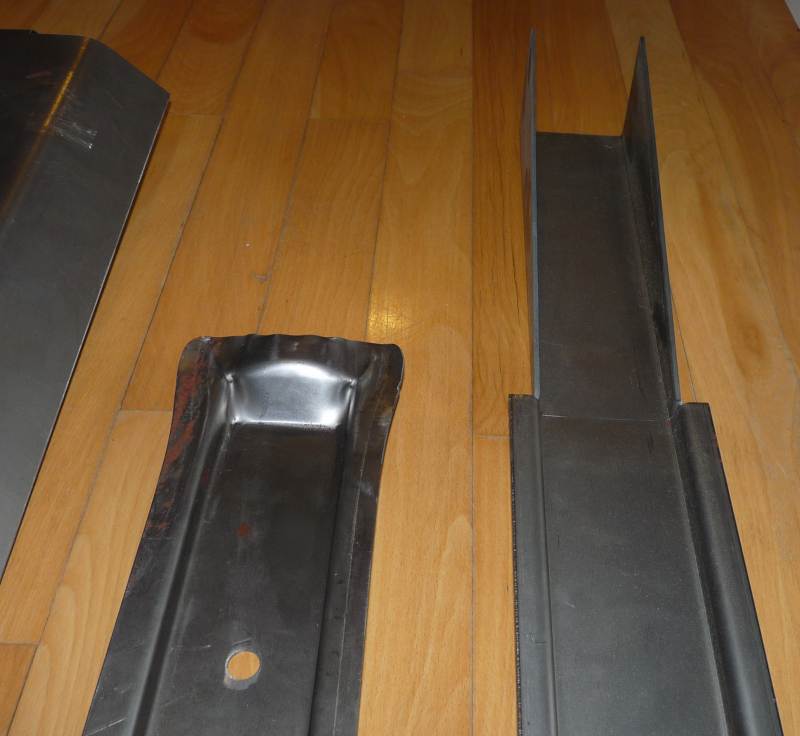
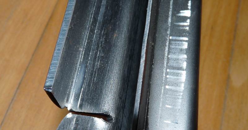
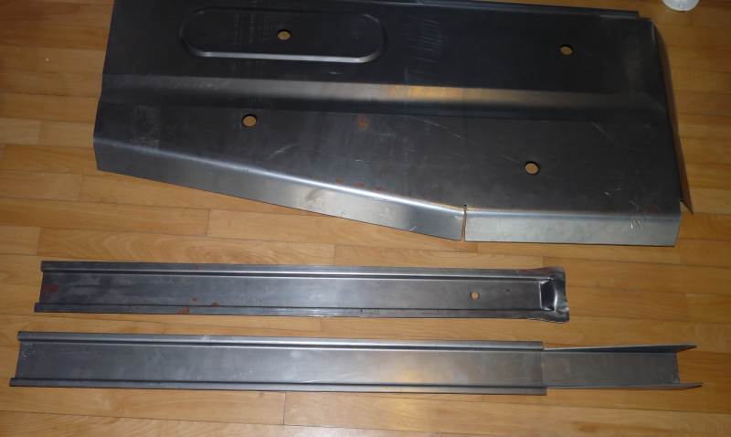
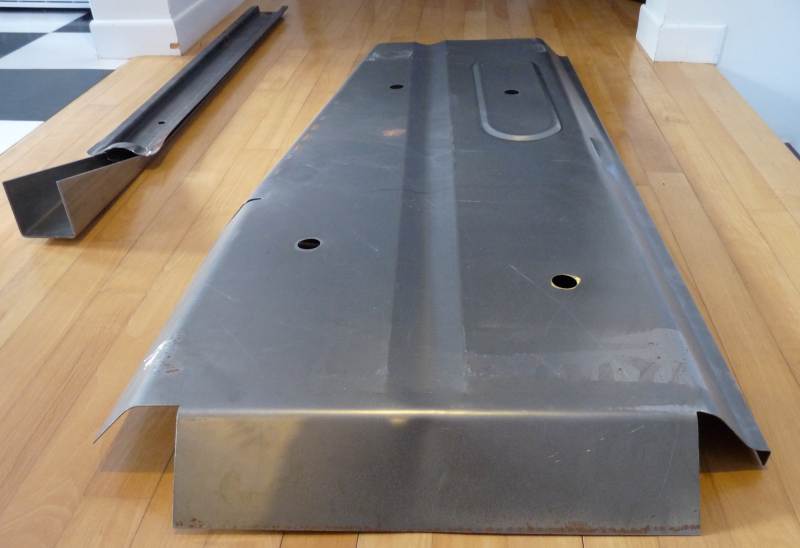
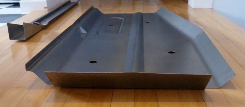
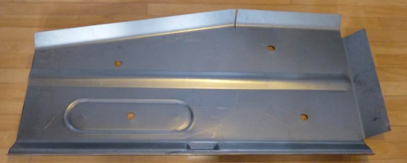
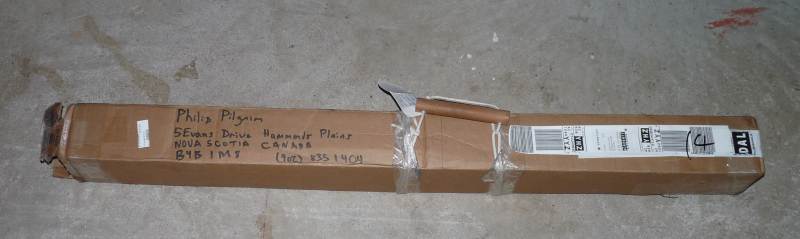
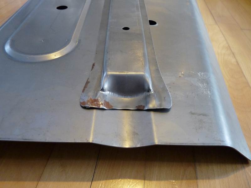
 Sure Esprist, Please post them to this thread. Wouldn't it be great if every Z part was photo documented in a separate thread on this site? hint hint Here are pics of new part:
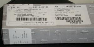
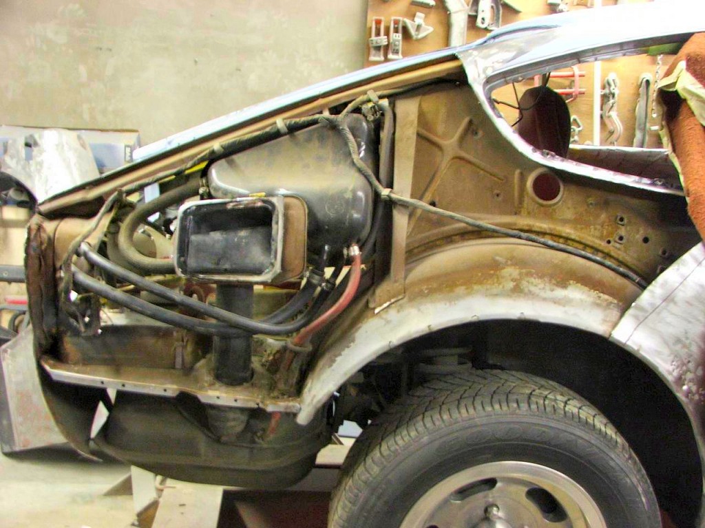
 Floor pans should be done one side at a time with the transmission mount in place and reference measurements made of the tunnel to rocker spacing before cutting. One of the priorities is to ensure the transmission tunnel stays centered and does not get smaller.


Important Information
By using this site, you agree to our Privacy Policy and Guidelines. We have placed cookies on your device to help make this website better. You can adjust your cookie settings, otherwise we'll assume you're okay to continue.
Account
Search
Configure browser push notifications
Chrome (Android)
- Tap the lock icon next to the address bar.
- Tap Permissions → Notifications.
- Adjust your preference.
Chrome (Desktop)
- Click the padlock icon in the address bar.
- Select Site settings.
- Find Notifications and adjust your preference.
Safari (iOS 16.4+)
- Ensure the site is installed via Add to Home Screen.
- Open Settings App → Notifications.
- Find your app name and adjust your preference.
Safari (macOS)
- Go to Safari → Preferences.
- Click the Websites tab.
- Select Notifications in the sidebar.
- Find this website and adjust your preference.
Edge (Android)
- Tap the lock icon next to the address bar.
- Tap Permissions.
- Find Notifications and adjust your preference.
Edge (Desktop)
- Click the padlock icon in the address bar.
- Click Permissions for this site.
- Find Notifications and adjust your preference.
Firefox (Android)
- Go to Settings → Site permissions.
- Tap Notifications.
- Find this site in the list and adjust your preference.
Firefox (Desktop)
- Open Firefox Settings.
- Search for Notifications.
- Find this site in the list and adjust your preference.