


240260280z
Free Member
-
Joined
-
Last visited
Everything posted by 240260280z
-
 Made a template from the tattered remains. I will drag it back to Canada and test fit then cut the materials after the test fit.
 http://youtu.be/zXRDiToE4gIhttp://youtu.be/zXRDiToE4gI
Beautiful work!
You gotta take it to a German track that looks like it's sister:
Drove up to Boston and spent the afternoon with Baddog. It is always a pleasure to see his Rebello powered G-Nose. (I think it is the perfect Z). This time it was at the Lars Anderson museum. There was a Japanese import show with lots of Datuns from the ZCCNE including modern GT-R's. My fav. oldie was a silver 1600 roadster. I met a few folks from the club then we crated up a dash bound for California. Got to see a 65 Ferrari 275 too!
http://youtu.be/zXRDiToE4gIhttp://youtu.be/zXRDiToE4gI
Beautiful work!
You gotta take it to a German track that looks like it's sister:
Drove up to Boston and spent the afternoon with Baddog. It is always a pleasure to see his Rebello powered G-Nose. (I think it is the perfect Z). This time it was at the Lars Anderson museum. There was a Japanese import show with lots of Datuns from the ZCCNE including modern GT-R's. My fav. oldie was a silver 1600 roadster. I met a few folks from the club then we crated up a dash bound for California. Got to see a 65 Ferrari 275 too! How about this one? http://westslope.craigslist.org/cto/2528862259.html
Bring chalk to car shows and let the kids "have at it". It would be fun for all.
Recently a member had an unusual problem. The manifold casting eroded under the EGR allowing exhaust to go directly into the intake plenum. Here is a photo of a white wire threaded through the hole. His symptom was low vacuum and fouling of #6:
I assume the tierod is attached to the knuckle arm? If you plan to replace tie rod, do this: Back off castellated nut so that the top of the nut is flush with the stud. Secure the knuckle arm and hammer the top of the nut&stud to drive it out of the knuckle arm. (This usually messes up the threads unless you are careful, or use a brass hammer, or use a brass plate in between. If you have problems because of "floppy", and hammering is difficult; then buy or borrow or rent the correct tool: Ball Joint Separator of correct size. Here is a random example of what they look like:
Bummer. Seem like the home stretch however: Either the fuel pressure is too high our your ECU is doing something it should not.
If you scratch your nails on it, do people run away or do they look at your brakes?
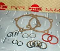
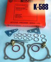
Just to update this thread (6 years later on): It is interesting that prices have not changed much! I just picked up two SU kits from Black Dragon (Victoria British) and the quality was poor thus the spur to revise this post. Black Dragon Manufacturer: Wells Part Number: CK749 It only includes: - Fuel bowl needle valve assembly and gasket (much shorter assembly than the two I have in the carbs and not easy to disassemble like the originals). - Fuel bowl top gasket (very thin paper material) - Carb to manifold gasket (very thin paper material) - Rubber gasket for plunger (very thin rubber) - Clear plastic spacer for spring base (very thin clear plastic) - Fuel bowl drain gasket - 2 paper washers different colours and materials (for fuel banjo I assume?) I was hoping they would be aluminum like the existing ones. - 3 mystery paper washers (not sure where they go? ID of hole is 10mm and OD of washer is 14mm) Any ideas? Cooling passages? - fuel hose (best part of kit) The gasket paper changed between the two kits I received. The documentation was generic and did not show where gaskets go however it was informative: Page1:su carb.PDF Page2:sucarb2.PDF This is my 2nd kit. At least the gasket material is the same in this one. Comments: This kit needs front gasket for carb and metal banjo gaskets then it would not be so bad. A fuel filter sock, taller needle valves, and better quality paper would also be improvements. Z Therapy ZT150 $180.00 Complete Tune Up Kit for 2 carbs (Needle & seats, SM, N27, N54, or N58 needles, ZT Nozzles, float gaskets, gas lines, banjo seals,4 insulator gaskets, JustSU's DVD) This cost includes a $50 CORE CHARGE on your old nozzles. Send back your old nozzles for $50 refund. Comments: The ZT kit is more of a serious overhaul kit than a refresh kit. It has too much core stuff that I do not need to change (DVD, Nozzles, Needles) . As well the core hassle for nozzle exchange is not my cup of tea. I think ZT would benefit from adding a basic refresh kit to their product line. (quality gaskets & hose & needle valves) Motorsport Auto I looked at the MSA kit and it looks a lot like the kit I received from BD only it is ~ 50% more expensive. Even the way the wire holds the needle assembly is the same. Ebay This all Nissan kit from Japan is good value for $30. Does two carbs. Best Value seems to be this 72 240z Keyster Kit for $30. It does two carbs and has needles too! Needle valves look aftermarket.
How about this one? http://westslope.craigslist.org/cto/2528862259.html
Bring chalk to car shows and let the kids "have at it". It would be fun for all.
Recently a member had an unusual problem. The manifold casting eroded under the EGR allowing exhaust to go directly into the intake plenum. Here is a photo of a white wire threaded through the hole. His symptom was low vacuum and fouling of #6:
I assume the tierod is attached to the knuckle arm? If you plan to replace tie rod, do this: Back off castellated nut so that the top of the nut is flush with the stud. Secure the knuckle arm and hammer the top of the nut&stud to drive it out of the knuckle arm. (This usually messes up the threads unless you are careful, or use a brass hammer, or use a brass plate in between. If you have problems because of "floppy", and hammering is difficult; then buy or borrow or rent the correct tool: Ball Joint Separator of correct size. Here is a random example of what they look like:
Bummer. Seem like the home stretch however: Either the fuel pressure is too high our your ECU is doing something it should not.
If you scratch your nails on it, do people run away or do they look at your brakes?
Just to update this thread (6 years later on): It is interesting that prices have not changed much! I just picked up two SU kits from Black Dragon (Victoria British) and the quality was poor thus the spur to revise this post. Black Dragon Manufacturer: Wells Part Number: CK749 It only includes: - Fuel bowl needle valve assembly and gasket (much shorter assembly than the two I have in the carbs and not easy to disassemble like the originals). - Fuel bowl top gasket (very thin paper material) - Carb to manifold gasket (very thin paper material) - Rubber gasket for plunger (very thin rubber) - Clear plastic spacer for spring base (very thin clear plastic) - Fuel bowl drain gasket - 2 paper washers different colours and materials (for fuel banjo I assume?) I was hoping they would be aluminum like the existing ones. - 3 mystery paper washers (not sure where they go? ID of hole is 10mm and OD of washer is 14mm) Any ideas? Cooling passages? - fuel hose (best part of kit) The gasket paper changed between the two kits I received. The documentation was generic and did not show where gaskets go however it was informative: Page1:su carb.PDF Page2:sucarb2.PDF This is my 2nd kit. At least the gasket material is the same in this one. Comments: This kit needs front gasket for carb and metal banjo gaskets then it would not be so bad. A fuel filter sock, taller needle valves, and better quality paper would also be improvements. Z Therapy ZT150 $180.00 Complete Tune Up Kit for 2 carbs (Needle & seats, SM, N27, N54, or N58 needles, ZT Nozzles, float gaskets, gas lines, banjo seals,4 insulator gaskets, JustSU's DVD) This cost includes a $50 CORE CHARGE on your old nozzles. Send back your old nozzles for $50 refund. Comments: The ZT kit is more of a serious overhaul kit than a refresh kit. It has too much core stuff that I do not need to change (DVD, Nozzles, Needles) . As well the core hassle for nozzle exchange is not my cup of tea. I think ZT would benefit from adding a basic refresh kit to their product line. (quality gaskets & hose & needle valves) Motorsport Auto I looked at the MSA kit and it looks a lot like the kit I received from BD only it is ~ 50% more expensive. Even the way the wire holds the needle assembly is the same. Ebay This all Nissan kit from Japan is good value for $30. Does two carbs. Best Value seems to be this 72 240z Keyster Kit for $30. It does two carbs and has needles too! Needle valves look aftermarket.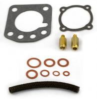


 Looks nice. Fix up the body first then think about what to do after. When you focus on the body work, you will have time for planning and considering what you want as well as investigating effort and costs to achieve your decision.
[TABLE] <tbody>[TR] [TD=bgcolor: #FFFFFF, colspan: 4]Nissan Brake Master Cylinder[/TD] [/TR] [TR] [TD]Item No.[/TD] [TD=width: 224, bgcolor: #FFFFFF]Description[/TD] [TD=width: 63, bgcolor: #FFFFFF]Diameter[/TD] [TD=width: 77, bgcolor: #FFFFFF]Year[/TD] [/TR] [TR] [TD=bgcolor: #FFFFFF]450028T[/TD] [TD=bgcolor: #FFFFFF] [/TD] [TD=bgcolor: #FFFFFF]3/4-15/16[/TD] [TD=bgcolor: #FFFFFF] [/TD] [/TR] [TR] [TD=bgcolor: #FFFFFF]450044T[/TD] [TD=bgcolor: #FFFFFF] [/TD] [TD=bgcolor: #FFFFFF]15/16[/TD] [TD=bgcolor: #FFFFFF] [/TD] [/TR] [TR] [TD=bgcolor: #FFFFFF]46010- C8000[/TD] [TD=bgcolor: #FFFFFF]160 PATROL[/TD] [TD=bgcolor: #FFFFFF]1"[/TD] [TD=bgcolor: #FFFFFF]1982~83[/TD] [/TR] [TR] [TD=bgcolor: #FFFFFF]46010-01A00[/TD] [TD=bgcolor: #FFFFFF]SENTRA B11,N12[/TD] [TD=bgcolor: #FFFFFF]3/4-15/16[/TD] [TD=bgcolor: #FFFFFF]1981~84[/TD] [/TR] [TR] [TD=bgcolor: #FFFFFF]46010-01A05[/TD] [TD=bgcolor: #FFFFFF]PULSAR B11,N12[/TD] [TD=bgcolor: #FFFFFF]3/4-15/16[/TD] [TD=bgcolor: #FFFFFF]1981~84[/TD] [/TR] [TR] [TD=bgcolor: #FFFFFF]46010-01B00[/TD] [TD=bgcolor: #FFFFFF]K10 MARCH[/TD] [TD=bgcolor: #FFFFFF]3/4-15/16[/TD] [TD=bgcolor: #FFFFFF]1982~84[/TD] [/TR] [TR] [TD=bgcolor: #FFFFFF]46010-01B05[/TD] [TD=bgcolor: #FFFFFF]K10 MARCH[/TD] [TD=bgcolor: #FFFFFF]3/4-15/16[/TD] [TD=bgcolor: #FFFFFF]1984[/TD] [/TR] [TR] [TD=bgcolor: #FFFFFF]46010-01B15[/TD] [TD=bgcolor: #FFFFFF]K10 MARCH[/TD] [TD=bgcolor: #FFFFFF]3/4-15/16[/TD] [TD=bgcolor: #FFFFFF]1985[/TD] [/TR] [TR] [TD=bgcolor: #FFFFFF]46010-01C00[/TD] [TD=bgcolor: #FFFFFF]C120, C20[/TD] [TD=bgcolor: #FFFFFF]13/16[/TD] [TD=bgcolor: #FFFFFF]1978[/TD] [/TR] [TR] [TD=bgcolor: #FFFFFF]46010-01G00[/TD] [TD=bgcolor: #FFFFFF] [/TD] [TD=bgcolor: #FFFFFF]1"[/TD] [TD=bgcolor: #FFFFFF] [/TD] [/TR] [TR] [TD=bgcolor: #FFFFFF]46010-01L00[/TD] [TD=bgcolor: #FFFFFF]S10 200B[/TD] [TD=bgcolor: #FFFFFF]7/8[/TD] [TD=bgcolor: #FFFFFF]1979[/TD] [/TR] [TR] [TD=bgcolor: #FFFFFF]46010-01W10[/TD] [TD=bgcolor: #FFFFFF]720 PICK UP[/TD] [TD=bgcolor: #FFFFFF]7/8[/TD] [TD=bgcolor: #FFFFFF]1980[/TD] [/TR] [TR] [TD=bgcolor: #FFFFFF]46010-02W10[/TD] [TD=bgcolor: #FFFFFF]720 PICK UP[/TD] [TD=bgcolor: #FFFFFF]7/8[/TD] [TD=bgcolor: #FFFFFF]1980~82[/TD] [/TR] [TR] [TD=bgcolor: #FFFFFF]46010-03A00[/TD] [TD=bgcolor: #FFFFFF]N12 PULSAR[/TD] [TD=bgcolor: #FFFFFF]3/4-15/16[/TD] [TD=bgcolor: #FFFFFF]1982~84[/TD] [/TR] [TR] [TD=bgcolor: #FFFFFF]46010-03A05[/TD] [TD=bgcolor: #FFFFFF]N12 PULSAR[/TD] [TD=bgcolor: #FFFFFF]3/4-15/16[/TD] [TD=bgcolor: #FFFFFF]1982~84[/TD] [/TR] [TR] [TD=bgcolor: #FFFFFF]46010-03R00[/TD] [TD=bgcolor: #FFFFFF]B11[/TD] [TD=bgcolor: #FFFFFF]13/16-1"[/TD] [TD=bgcolor: #FFFFFF]1983~86[/TD] [/TR] [TR] [TD=bgcolor: #FFFFFF]46010-03R05[/TD] [TD=bgcolor: #FFFFFF] [/TD] [TD=bgcolor: #FFFFFF]13/16-1"[/TD] [TD=bgcolor: #FFFFFF] [/TD] [/TR] [TR] [TD=bgcolor: #FFFFFF]46010-04920[/TD] [TD=bgcolor: #FFFFFF] [/TD] [TD=bgcolor: #FFFFFF]15/16[/TD] [TD=bgcolor: #FFFFFF] [/TD] [/TR] [TR] [TD=bgcolor: #FFFFFF]46010-04B00[/TD] [TD=bgcolor: #FFFFFF]N12 PULSAR[/TD] [TD=bgcolor: #FFFFFF]3/4-15/16[/TD] [TD=bgcolor: #FFFFFF]1984~87[/TD] [/TR] [TR] [TD=bgcolor: #FFFFFF]46010-04B05[/TD] [TD=bgcolor: #FFFFFF]N12 PULSAR[/TD] [TD=bgcolor: #FFFFFF]3/4-15/16[/TD] [TD=bgcolor: #FFFFFF]1984~87[/TD] [/TR] [TR] [TD=bgcolor: #FFFFFF]46010-04B10[/TD] [TD=bgcolor: #FFFFFF]K10 MARCH[/TD] [TD=bgcolor: #FFFFFF]3/4-15/16[/TD] [TD=bgcolor: #FFFFFF]1982~84[/TD] [/TR] [TR] [TD=bgcolor: #FFFFFF]46010-04B15[/TD] [TD=bgcolor: #FFFFFF]K10 MARCH[/TD] [TD=bgcolor: #FFFFFF]3/4-15/16[/TD] [TD=bgcolor: #FFFFFF]1984[/TD] [/TR] [TR] [TD=bgcolor: #FFFFFF]46010-04P00[/TD] [TD=bgcolor: #FFFFFF] [/TD] [TD=bgcolor: #FFFFFF]15/16[/TD] [TD=bgcolor: #FFFFFF] [/TD] [/TR] [TR] [TD=bgcolor: #FFFFFF]46010-04P20[/TD] [TD=bgcolor: #FFFFFF] [/TD] [TD=bgcolor: #FFFFFF]15/16[/TD] [TD=bgcolor: #FFFFFF] [/TD] [/TR] [TR] [TD=bgcolor: #FFFFFF]46010-05W01[/TD] [TD=bgcolor: #FFFFFF]720 PICK UP[/TD] [TD=bgcolor: #FFFFFF]7/8[/TD] [TD=bgcolor: #FFFFFF]1979~80[/TD] [/TR] [TR] [TD=bgcolor: #FFFFFF]46010-07P06[/TD] [TD=bgcolor: #FFFFFF] [/TD] [TD=bgcolor: #FFFFFF]7/8[/TD] [TD=bgcolor: #FFFFFF] [/TD] [/TR] [TR] [TD=bgcolor: #FFFFFF]46010-09G00[/TD] [TD=bgcolor: #FFFFFF] [/TD] [TD=bgcolor: #FFFFFF]11/16[/TD] [TD=bgcolor: #FFFFFF] [/TD] [/TR] [TR] [TD=bgcolor: #FFFFFF]46010-09L00[/TD] [TD=bgcolor: #FFFFFF]S10 200B[/TD] [TD=bgcolor: #FFFFFF]7/8[/TD] [TD=bgcolor: #FFFFFF]1979[/TD] [/TR] [TR] [TD=bgcolor: #FFFFFF]46010-0B000[/TD] [TD=bgcolor: #FFFFFF] [/TD] [TD=bgcolor: #FFFFFF]1"[/TD] [TD=bgcolor: #FFFFFF] [/TD] [/TR] [TR] [TD=bgcolor: #FFFFFF]46010-0B001[/TD] [TD=bgcolor: #FFFFFF] [/TD] [TD=bgcolor: #FFFFFF]1"[/TD] [TD=bgcolor: #FFFFFF] [/TD] [/TR] [TR] [TD=bgcolor: #FFFFFF]46010-0B002[/TD] [TD=bgcolor: #FFFFFF] [/TD] [TD=bgcolor: #FFFFFF]1"[/TD] [TD=bgcolor: #FFFFFF] [/TD] [/TR] [TR] [TD=bgcolor: #FFFFFF]46010-0B003[/TD] [TD=bgcolor: #FFFFFF] [/TD] [TD=bgcolor: #FFFFFF]1"[/TD] [TD=bgcolor: #FFFFFF] [/TD] [/TR] [TR] [TD=bgcolor: #FFFFFF]46010-0B005[/TD] [TD=bgcolor: #FFFFFF] [/TD] [TD=bgcolor: #FFFFFF]1"[/TD] [TD=bgcolor: #FFFFFF] [/TD] [/TR] [TR] [TD=bgcolor: #FFFFFF]46010-0W002[/TD] [TD=bgcolor: #FFFFFF]PATHFINDER[/TD] [TD=bgcolor: #FFFFFF]1[/TD] [TD=bgcolor: #FFFFFF]1998~[/TD] [/TR] [TR] [TD=bgcolor: #FFFFFF]46010-0W022[/TD] [TD=bgcolor: #FFFFFF]PATHFINDER[/TD] [TD=bgcolor: #FFFFFF]1[/TD] [TD=bgcolor: #FFFFFF]1998~[/TD] [/TR] [TR] [TD=bgcolor: #FFFFFF]46010-11W00[/TD] [TD=bgcolor: #FFFFFF]720 PICK UP[/TD] [TD=bgcolor: #FFFFFF]7/8[/TD] [TD=bgcolor: #FFFFFF]1979~80[/TD] [/TR] [TR] [TD=bgcolor: #FFFFFF]46010-12W00[/TD] [TD=bgcolor: #FFFFFF]720[/TD] [TD=bgcolor: #FFFFFF]7/8[/TD] [TD=bgcolor: #FFFFFF]1980[/TD] [/TR] [TR] [TD=bgcolor: #FFFFFF]46010-12W10[/TD] [TD=bgcolor: #FFFFFF] [/TD] [TD=bgcolor: #FFFFFF]7/8[/TD] [TD=bgcolor: #FFFFFF] [/TD] [/TR] [TR] [TD=bgcolor: #FFFFFF]46010-13W00[/TD] [TD=bgcolor: #FFFFFF]720[/TD] [TD=bgcolor: #FFFFFF]7/8[/TD] [TD=bgcolor: #FFFFFF]1979~80[/TD] [/TR] [TR] [TD=bgcolor: #FFFFFF]46010-13W10[/TD] [TD=bgcolor: #FFFFFF]720 2WD 4WD[/TD] [TD=bgcolor: #FFFFFF]3/4[/TD] [TD=bgcolor: #FFFFFF]1980~83[/TD] [/TR] [TR] [TD=bgcolor: #FFFFFF]46010-14800[/TD] [TD=bgcolor: #FFFFFF]520[/TD] [TD=bgcolor: #FFFFFF]3/4[/TD] [TD=bgcolor: #FFFFFF]1967~71[/TD] [/TR] [TR] [TD=bgcolor: #FFFFFF]46010-14B05[/TD] [TD=bgcolor: #FFFFFF] [/TD] [TD=bgcolor: #FFFFFF]13/16~1"[/TD] [TD=bgcolor: #FFFFFF] [/TD] [/TR] [TR] [TD=bgcolor: #FFFFFF]46010-14E00[/TD] [TD=bgcolor: #FFFFFF] [/TD] [TD=bgcolor: #FFFFFF]13/16~1"[/TD] [TD=bgcolor: #FFFFFF] [/TD] [/TR] [TR] [TD=bgcolor: #FFFFFF]46010-14E01[/TD] [TD=bgcolor: #FFFFFF] [/TD] [TD=bgcolor: #FFFFFF]3/4[/TD] [TD=bgcolor: #FFFFFF] [/TD] [/TR] [TR] [TD=bgcolor: #FFFFFF]46010-14E05[/TD] [TD=bgcolor: #FFFFFF] [/TD] [TD=bgcolor: #FFFFFF]13/16~1"[/TD] [TD=bgcolor: #FFFFFF] [/TD] [/TR] [TR] [TD=bgcolor: #FFFFFF]46010-14E10[/TD] [TD=bgcolor: #FFFFFF] [/TD] [TD=bgcolor: #FFFFFF]13/16~1"[/TD] [TD=bgcolor: #FFFFFF] [/TD] [/TR] [TR] [TD=bgcolor: #FFFFFF]46010-14E11[/TD] [TD=bgcolor: #FFFFFF] [/TD] [TD=bgcolor: #FFFFFF]13/16~1"[/TD] [TD=bgcolor: #FFFFFF] [/TD] [/TR] [TR] [TD=bgcolor: #FFFFFF]46010-15G01[/TD] [TD=bgcolor: #FFFFFF]D21 PICK UP[/TD] [TD=bgcolor: #FFFFFF]15/16[/TD] [TD=bgcolor: #FFFFFF]1985[/TD] [/TR] [TR] [TD=bgcolor: #FFFFFF]46010-16A00[/TD] [TD=bgcolor: #FFFFFF] [/TD] [TD=bgcolor: #FFFFFF]3/4-15/16[/TD] [TD=bgcolor: #FFFFFF] [/TD] [/TR] [TR] [TD=bgcolor: #FFFFFF]46010-16A05[/TD] [TD=bgcolor: #FFFFFF] [/TD] [TD=bgcolor: #FFFFFF]3/4-15/16[/TD] [TD=bgcolor: #FFFFFF] [/TD] [/TR] [TR] [TD=bgcolor: #FFFFFF]46010-18F20[/TD] [TD=bgcolor: #FFFFFF] [/TD] [TD=bgcolor: #FFFFFF]15/16[/TD] [TD=bgcolor: #FFFFFF] [/TD] [/TR] [TR] [TD=bgcolor: #FFFFFF]46010-18F20[/TD] [TD=bgcolor: #FFFFFF] [/TD] [TD=bgcolor: #FFFFFF]15/16[/TD] [TD=bgcolor: #FFFFFF] [/TD] [/TR] [TR] [TD=bgcolor: #FFFFFF]46010-18W00[/TD] [TD=bgcolor: #FFFFFF]720 PICK UP[/TD] [TD=bgcolor: #FFFFFF]7/8[/TD] [TD=bgcolor: #FFFFFF]1981[/TD] [/TR] [TR] [TD=bgcolor: #FFFFFF]46010-18W10[/TD] [TD=bgcolor: #FFFFFF]910[/TD] [TD=bgcolor: #FFFFFF]7/8[/TD] [TD=bgcolor: #FFFFFF]1980~83[/TD] [/TR] [TR] [TD=bgcolor: #FFFFFF]46010-19L01[/TD] [TD=bgcolor: #FFFFFF]D21[/TD] [TD=bgcolor: #FFFFFF]15/16[/TD] [TD=bgcolor: #FFFFFF]1986~[/TD] [/TR] [TR] [TD=bgcolor: #FFFFFF]46010-1E305[/TD] [TD=bgcolor: #FFFFFF] [/TD] [TD=bgcolor: #FFFFFF]3/4[/TD] [TD=bgcolor: #FFFFFF] [/TD] [/TR] [TR] [TD=bgcolor: #FFFFFF]46010-1E400[/TD] [TD=bgcolor: #FFFFFF]ALTIMA[/TD] [TD=bgcolor: #FFFFFF]15/16[/TD] [TD=bgcolor: #FFFFFF]1993~[/TD] [/TR] [TR] [TD=bgcolor: #FFFFFF]46010-1E401[/TD] [TD=bgcolor: #FFFFFF]CEFIRO A31,A32[/TD] [TD=bgcolor: #FFFFFF]15/16[/TD] [TD=bgcolor: #FFFFFF]1995~[/TD] [/TR] [TR] [TD=bgcolor: #FFFFFF]46010-1E412[/TD] [TD=bgcolor: #FFFFFF]ALTIMA[/TD] [TD=bgcolor: #FFFFFF]1"[/TD] [TD=bgcolor: #FFFFFF]1993~[/TD] [/TR] [TR] [TD=bgcolor: #FFFFFF]46010-1M320[/TD] [TD=bgcolor: #FFFFFF]SENTRA,200SXW/O ABS[/TD] [TD=bgcolor: #FFFFFF]13/16[/TD] [TD=bgcolor: #FFFFFF]1995~[/TD] [/TR] [TR] [TD=bgcolor: #FFFFFF]46010-21000[/TD] [TD=bgcolor: #FFFFFF] [/TD] [TD=bgcolor: #FFFFFF]3/4[/TD] [TD=bgcolor: #FFFFFF] [/TD] [/TR] [TR] [TD=bgcolor: #FFFFFF]46010-21001[/TD] [TD=bgcolor: #FFFFFF]510[/TD] [TD=bgcolor: #FFFFFF]3/4[/TD] [TD=bgcolor: #FFFFFF]1968~71[/TD] [/TR] [TR] [TD=bgcolor: #FFFFFF]46010-22F00[/TD] [TD=bgcolor: #FFFFFF] [/TD] [TD=bgcolor: #FFFFFF]15/16[/TD] [TD=bgcolor: #FFFFFF] [/TD] [/TR] [TR] [TD=bgcolor: #FFFFFF]46010-22F20[/TD] [TD=bgcolor: #FFFFFF]S12[/TD] [TD=bgcolor: #FFFFFF]15/16[/TD] [TD=bgcolor: #FFFFFF]1983~88[/TD] [/TR] [TR] [TD=bgcolor: #FFFFFF]46010-25F23[/TD] [TD=bgcolor: #FFFFFF] [/TD] [TD=bgcolor: #FFFFFF]15/16[/TD] [TD=bgcolor: #FFFFFF] [/TD] [/TR] [TR] [TD=bgcolor: #FFFFFF]46010-25G00[/TD] [TD=bgcolor: #FFFFFF]D21[/TD] [TD=bgcolor: #FFFFFF]15/16[/TD] [TD=bgcolor: #FFFFFF]1986[/TD] [/TR] [TR] [TD=bgcolor: #FFFFFF]46010-2B100[/TD] [TD=bgcolor: #FFFFFF]ALTIMA[/TD] [TD=bgcolor: #FFFFFF]15/16[/TD] [TD=bgcolor: #FFFFFF]1993~[/TD] [/TR] [TR] [TD=bgcolor: #FFFFFF]46010-2B101[/TD] [TD=bgcolor: #FFFFFF]CEFIRO A31,32[/TD] [TD=bgcolor: #FFFFFF]15/16[/TD] [TD=bgcolor: #FFFFFF]1995~[/TD] [/TR] [TR] [TD=bgcolor: #FFFFFF]46010-2M101[/TD] [TD=bgcolor: #FFFFFF]B14[/TD] [TD=bgcolor: #FFFFFF]7/8[/TD] [TD=bgcolor: #FFFFFF] [/TD] [/TR] [TR] [TD=bgcolor: #FFFFFF]46010-30001[/TD] [TD=bgcolor: #FFFFFF] [/TD] [TD=bgcolor: #FFFFFF]3/4[/TD] [TD=bgcolor: #FFFFFF] [/TD] [/TR] [TR] [TD=bgcolor: #FFFFFF]46010-30W00[/TD] [TD=bgcolor: #FFFFFF]PATROL 160[/TD] [TD=bgcolor: #FFFFFF]15/16[/TD] [TD=bgcolor: #FFFFFF]1980[/TD] [/TR] [TR] [TD=bgcolor: #FFFFFF]46010-31W00[/TD] [TD=bgcolor: #FFFFFF] [/TD] [TD=bgcolor: #FFFFFF]15/16[/TD] [TD=bgcolor: #FFFFFF] [/TD] [/TR] [TR] [TD=bgcolor: #FFFFFF]46010-32F20[/TD] [TD=bgcolor: #FFFFFF] [/TD] [TD=bgcolor: #FFFFFF]15/16[/TD] [TD=bgcolor: #FFFFFF] [/TD] [/TR] [TR] [TD=bgcolor: #FFFFFF]46010-34A00[/TD] [TD=bgcolor: #FFFFFF] [/TD] [TD=bgcolor: #FFFFFF]13/16-1"[/TD] [TD=bgcolor: #FFFFFF] [/TD] [/TR] [TR] [TD=bgcolor: #FFFFFF]46010-34A01[/TD] [TD=bgcolor: #FFFFFF]N12 PULSAR[/TD] [TD=bgcolor: #FFFFFF]3/4-15/16[/TD] [TD=bgcolor: #FFFFFF]1982[/TD] [/TR] [TR] [TD=bgcolor: #FFFFFF]46010-34A01[/TD] [TD=bgcolor: #FFFFFF]N12 PULSAR[/TD] [TD=bgcolor: #FFFFFF]3/4-15/16[/TD] [TD=bgcolor: #FFFFFF]1982[/TD] [/TR] [TR] [TD=bgcolor: #FFFFFF]46010-34A05[/TD] [TD=bgcolor: #FFFFFF] [/TD] [TD=bgcolor: #FFFFFF]13/16-1"[/TD] [TD=bgcolor: #FFFFFF] [/TD] [/TR] [TR] [TD=bgcolor: #FFFFFF]46010-34A06[/TD] [TD=bgcolor: #FFFFFF]N12 PULSAR[/TD] [TD=bgcolor: #FFFFFF]3/4-15/16[/TD] [TD=bgcolor: #FFFFFF]1982[/TD] [/TR] [TR] [TD=bgcolor: #FFFFFF]46010-34A06[/TD] [TD=bgcolor: #FFFFFF]N12 PULSAR[/TD] [TD=bgcolor: #FFFFFF]3/4-15/16[/TD] [TD=bgcolor: #FFFFFF]1982[/TD] [/TR] [TR] [TD=bgcolor: #FFFFFF]46010-34W00[/TD] [TD=bgcolor: #FFFFFF]720 PICK UP[/TD] [TD=bgcolor: #FFFFFF]7/8[/TD] [TD=bgcolor: #FFFFFF]1980[/TD] [/TR] [TR] [TD=bgcolor: #FFFFFF]46010-34W10[/TD] [TD=bgcolor: #FFFFFF]720 PICK UP[/TD] [TD=bgcolor: #FFFFFF]7/8[/TD] [TD=bgcolor: #FFFFFF]1981[/TD] [/TR] [TR] [TD=bgcolor: #FFFFFF]46010-3T900[/TD] [TD=bgcolor: #FFFFFF] [/TD] [TD=bgcolor: #FFFFFF]1"[/TD] [TD=bgcolor: #FFFFFF] [/TD] [/TR] [TR] [TD=bgcolor: #FFFFFF]46010-40110[/TD] [TD=bgcolor: #FFFFFF]PATROL 60[/TD] [TD=bgcolor: #FFFFFF]15/16[/TD] [TD=bgcolor: #FFFFFF] [/TD] [/TR] [TR] [TD=bgcolor: #FFFFFF]46010-40U05[/TD] [TD=bgcolor: #FFFFFF]MA ×1 MA[/TD] [TD=bgcolor: #FFFFFF]15/16[/TD] [TD=bgcolor: #FFFFFF]1994~[/TD] [/TR] [TR] [TD=bgcolor: #FFFFFF]46010-41V00[/TD] [TD=bgcolor: #FFFFFF] [/TD] [TD=bgcolor: #FFFFFF]15/16[/TD] [TD=bgcolor: #FFFFFF] [/TD] [/TR] [TR] [TD=bgcolor: #FFFFFF]46010-43U00[/TD] [TD=bgcolor: #FFFFFF]CEFIRO[/TD] [TD=bgcolor: #FFFFFF]15/16[/TD] [TD=bgcolor: #FFFFFF]1995~[/TD] [/TR] [TR] [TD=bgcolor: #FFFFFF]46010-44001[/TD] [TD=bgcolor: #FFFFFF]PATROL 60[/TD] [TD=bgcolor: #FFFFFF]1"[/TD] [TD=bgcolor: #FFFFFF]1969~79[/TD] [/TR] [TR] [TD=bgcolor: #FFFFFF]46010-44001[/TD] [TD=bgcolor: #FFFFFF] [/TD] [TD=bgcolor: #FFFFFF]1"[/TD] [TD=bgcolor: #FFFFFF] [/TD] [/TR] [TR] [TD=bgcolor: #FFFFFF]46010-46502[/TD] [TD=bgcolor: #FFFFFF]PATROL 60[/TD] [TD=bgcolor: #FFFFFF]1"[/TD] [TD=bgcolor: #FFFFFF]1970[/TD] [/TR] [TR] [TD=bgcolor: #FFFFFF]46010-46502[/TD] [TD=bgcolor: #FFFFFF] [/TD] [TD=bgcolor: #FFFFFF]1"[/TD] [TD=bgcolor: #FFFFFF] [/TD] [/TR] [TR] [TD=bgcolor: #FFFFFF]46010-46700[/TD] [TD=bgcolor: #FFFFFF]PATROL 60[/TD] [TD=bgcolor: #FFFFFF]1"[/TD] [TD=bgcolor: #FFFFFF]1979[/TD] [/TR] [TR] [TD=bgcolor: #FFFFFF]46010-48W00[/TD] [TD=bgcolor: #FFFFFF]720 2WD 4WD[/TD] [TD=bgcolor: #FFFFFF]7/8[/TD] [TD=bgcolor: #FFFFFF]1980~83[/TD] [/TR] [TR] [TD=bgcolor: #FFFFFF]46010-49L01[/TD] [TD=bgcolor: #FFFFFF]D21 PICK UP[/TD] [TD=bgcolor: #FFFFFF]15/16[/TD] [TD=bgcolor: #FFFFFF]1986[/TD] [/TR] [TR] [TD=bgcolor: #FFFFFF]46010-4B000[/TD] [TD=bgcolor: #FFFFFF] [/TD] [TD=bgcolor: #FFFFFF]13/16[/TD] [TD=bgcolor: #FFFFFF] [/TD] [/TR] [TR] [TD=bgcolor: #FFFFFF]46010-50W10[/TD] [TD=bgcolor: #FFFFFF]720 PICK UP[/TD] [TD=bgcolor: #FFFFFF]15/16[/TD] [TD=bgcolor: #FFFFFF]1980[/TD] [/TR] [TR] [TD=bgcolor: #FFFFFF]46010-52A00[/TD] [TD=bgcolor: #FFFFFF] [/TD] [TD=bgcolor: #FFFFFF]3/4-15/16[/TD] [TD=bgcolor: #FFFFFF] [/TD] [/TR] [TR] [TD=bgcolor: #FFFFFF]46010-54W20[/TD] [TD=bgcolor: #FFFFFF]PATROL 160[/TD] [TD=bgcolor: #FFFFFF]15/16[/TD] [TD=bgcolor: #FFFFFF]1980[/TD] [/TR] [TR] [TD=bgcolor: #FFFFFF]46010-60A00[/TD] [TD=bgcolor: #FFFFFF] [/TD] [TD=bgcolor: #FFFFFF]13/16-1"[/TD] [TD=bgcolor: #FFFFFF] [/TD] [/TR] [TR] [TD=bgcolor: #FFFFFF]46010-60U10[/TD] [TD=bgcolor: #FFFFFF]Q45[/TD] [TD=bgcolor: #FFFFFF]1-1/16[/TD] [TD=bgcolor: #FFFFFF]1990~[/TD] [/TR] [TR] [TD=bgcolor: #FFFFFF]46010-60U11[/TD] [TD=bgcolor: #FFFFFF] [/TD] [TD=bgcolor: #FFFFFF]1"[/TD] [TD=bgcolor: #FFFFFF] [/TD] [/TR] [TR] [TD=bgcolor: #FFFFFF]46010-60Y71[/TD] [TD=bgcolor: #FFFFFF] [/TD] [TD=bgcolor: #FFFFFF]7/8[/TD] [TD=bgcolor: #FFFFFF] [/TD] [/TR] [TR] [TD=bgcolor: #FFFFFF]46010-62J03[/TD] [TD=bgcolor: #FFFFFF]G20,931[/TD] [TD=bgcolor: #FFFFFF]15/16[/TD] [TD=bgcolor: #FFFFFF]1992[/TD] [/TR] [TR] [TD=bgcolor: #FFFFFF]46010-62J12[/TD] [TD=bgcolor: #FFFFFF]G20,931[/TD] [TD=bgcolor: #FFFFFF]15/16[/TD] [TD=bgcolor: #FFFFFF]1990~95[/TD] [/TR] [TR] [TD=bgcolor: #FFFFFF]46010-62J21[/TD] [TD=bgcolor: #FFFFFF]G20[/TD] [TD=bgcolor: #FFFFFF]15/16[/TD] [TD=bgcolor: #FFFFFF]1994~[/TD] [/TR] [TR] [TD=bgcolor: #FFFFFF]46010-62J72[/TD] [TD=bgcolor: #FFFFFF]G20,931[/TD] [TD=bgcolor: #FFFFFF]15/16[/TD] [TD=bgcolor: #FFFFFF]1990~95[/TD] [/TR] [TR] [TD=bgcolor: #FFFFFF]46010-63C00[/TD] [TD=bgcolor: #FFFFFF] [/TD] [TD=bgcolor: #FFFFFF]13/16[/TD] [TD=bgcolor: #FFFFFF] [/TD] [/TR] [TR] [TD=bgcolor: #FFFFFF]46010-63C20[/TD] [TD=bgcolor: #FFFFFF]NX[/TD] [TD=bgcolor: #FFFFFF]13/16[/TD] [TD=bgcolor: #FFFFFF]1991~[/TD] [/TR] [TR] [TD=bgcolor: #FFFFFF]46010-65200[/TD] [TD=bgcolor: #FFFFFF] [/TD] [TD=bgcolor: #FFFFFF]1"[/TD] [TD=bgcolor: #FFFFFF] [/TD] [/TR] [TR] [TD=bgcolor: #FFFFFF]46010-65201[/TD] [TD=bgcolor: #FFFFFF]PATROL 60[/TD] [TD=bgcolor: #FFFFFF]1"[/TD] [TD=bgcolor: #FFFFFF]1973~77[/TD] [/TR] [TR] [TD=bgcolor: #FFFFFF]46010-65202[/TD] [TD=bgcolor: #FFFFFF]PATROL 60[/TD] [TD=bgcolor: #FFFFFF]1"[/TD] [TD=bgcolor: #FFFFFF]1967~79[/TD] [/TR] [TR] [TD=bgcolor: #FFFFFF]46010-65Y64[/TD] [TD=bgcolor: #FFFFFF] [/TD] [TD=bgcolor: #FFFFFF]7/8[/TD] [TD=bgcolor: #FFFFFF] [/TD] [/TR] [TR] [TD=bgcolor: #FFFFFF]46010-67A00[/TD] [TD=bgcolor: #FFFFFF]SENTRA,B12,PULSAR[/TD] [TD=bgcolor: #FFFFFF]3-4-15/16[/TD] [TD=bgcolor: #FFFFFF]1987[/TD] [/TR] [TR] [TD=bgcolor: #FFFFFF]46010-69Y20[/TD] [TD=bgcolor: #FFFFFF]NX[/TD] [TD=bgcolor: #FFFFFF]7/8[/TD] [TD=bgcolor: #FFFFFF]1991~[/TD] [/TR] [TR] [TD=bgcolor: #FFFFFF]46010-72Y04[/TD] [TD=bgcolor: #FFFFFF]SWNTRA,B13,331[/TD] [TD=bgcolor: #FFFFFF]3/4[/TD] [TD=bgcolor: #FFFFFF]1991~94[/TD] [/TR] [TR] [TD=bgcolor: #FFFFFF]46010-72Y22[/TD] [TD=bgcolor: #FFFFFF] [/TD] [TD=bgcolor: #FFFFFF]7/8[/TD] [TD=bgcolor: #FFFFFF] [/TD] [/TR] [TR] [TD=bgcolor: #FFFFFF]46010-72Y24[/TD] [TD=bgcolor: #FFFFFF]SENTER 1.3(LEC)/JX B13[/TD] [TD=bgcolor: #FFFFFF]3/4[/TD] [TD=bgcolor: #FFFFFF]1990~[/TD] [/TR] [TR] [TD=bgcolor: #FFFFFF]46010-72Y72[/TD] [TD=bgcolor: #FFFFFF]NX[/TD] [TD=bgcolor: #FFFFFF]7/8[/TD] [TD=bgcolor: #FFFFFF]1991~[/TD] [/TR] [TR] [TD=bgcolor: #FFFFFF]46010-85E23[/TD] [TD=bgcolor: #FFFFFF] [/TD] [TD=bgcolor: #FFFFFF]15/16[/TD] [TD=bgcolor: #FFFFFF] [/TD] [/TR] [TR] [TD=bgcolor: #FFFFFF]46010-88E21[/TD] [TD=bgcolor: #FFFFFF]J30[/TD] [TD=bgcolor: #FFFFFF]1"[/TD] [TD=bgcolor: #FFFFFF]1989[/TD] [/TR] [TR] [TD=bgcolor: #FFFFFF]46010-8B000[/TD] [TD=bgcolor: #FFFFFF]47.5mm[/TD] [TD=bgcolor: #FFFFFF]1"[/TD] [TD=bgcolor: #FFFFFF] [/TD] [/TR] [TR] [TD=bgcolor: #FFFFFF]46010-A03G0[/TD] [TD=bgcolor: #FFFFFF] [/TD] [TD=bgcolor: #FFFFFF]3/4-15/16[/TD] [TD=bgcolor: #FFFFFF] [/TD] [/TR] [TR] [TD=bgcolor: #FFFFFF]46010-A05G0[/TD] [TD=bgcolor: #FFFFFF] [/TD] [TD=bgcolor: #FFFFFF]3/4-15/16[/TD] [TD=bgcolor: #FFFFFF] [/TD] [/TR] [TR] [TD=bgcolor: #FFFFFF]46010-A0800[/TD] [TD=bgcolor: #FFFFFF]510[/TD] [TD=bgcolor: #FFFFFF]3/4[/TD] [TD=bgcolor: #FFFFFF]1969~71[/TD] [/TR] [TR] [TD=bgcolor: #FFFFFF]46010-A2200[/TD] [TD=bgcolor: #FFFFFF]510[/TD] [TD=bgcolor: #FFFFFF]3/4[/TD] [TD=bgcolor: #FFFFFF]1967~73[/TD] [/TR] [TR] [TD=bgcolor: #FFFFFF]46010-A2300[/TD] [TD=bgcolor: #FFFFFF]510[/TD] [TD=bgcolor: #FFFFFF]3/4[/TD] [TD=bgcolor: #FFFFFF]1968~71[/TD] [/TR] [TR] [TD=bgcolor: #FFFFFF]46010-A2400[/TD] [TD=bgcolor: #FFFFFF] [/TD] [TD=bgcolor: #FFFFFF]3/4[/TD] [TD=bgcolor: #FFFFFF] [/TD] [/TR] [TR] [TD=bgcolor: #FFFFFF]46010-A4600[/TD] [TD=bgcolor: #FFFFFF]510[/TD] [TD=bgcolor: #FFFFFF]3/4[/TD] [TD=bgcolor: #FFFFFF]1969~71[/TD] [/TR] [TR] [TD=bgcolor: #FFFFFF]46010-A5400[/TD] [TD=bgcolor: #FFFFFF]510[/TD] [TD=bgcolor: #FFFFFF]3/4[/TD] [TD=bgcolor: #FFFFFF]1968~71[/TD] [/TR] [TR] [TD=bgcolor: #FFFFFF]46010-A5405[/TD] [TD=bgcolor: #FFFFFF]510[/TD] [TD=bgcolor: #FFFFFF]3/4[/TD] [TD=bgcolor: #FFFFFF]1968~71[/TD] [/TR] [TR] [TD=bgcolor: #FFFFFF]46010-A6000[/TD] [TD=bgcolor: #FFFFFF] [/TD] [TD=bgcolor: #FFFFFF]3/4[/TD] [TD=bgcolor: #FFFFFF] [/TD] [/TR] [TR] [TD=bgcolor: #FFFFFF]46010-B3000[/TD] [TD=bgcolor: #FFFFFF]520[/TD] [TD=bgcolor: #FFFFFF]3/4[/TD] [TD=bgcolor: #FFFFFF]1967~71[/TD] [/TR] [TR] [TD=bgcolor: #FFFFFF]46010-B4000[/TD] [TD=bgcolor: #FFFFFF] [/TD] [TD=bgcolor: #FFFFFF]13/16[/TD] [TD=bgcolor: #FFFFFF] [/TD] [/TR] [TR] [TD=bgcolor: #FFFFFF]46010-B5000[/TD] [TD=bgcolor: #FFFFFF]B210,620[/TD] [TD=bgcolor: #FFFFFF]11/16[/TD] [TD=bgcolor: #FFFFFF]1971~75[/TD] [/TR] [TR] [TD=bgcolor: #FFFFFF]46010-B5002[/TD] [TD=bgcolor: #FFFFFF]620[/TD] [TD=bgcolor: #FFFFFF]3/4[/TD] [TD=bgcolor: #FFFFFF]1975[/TD] [/TR] [TR] [TD=bgcolor: #FFFFFF]46010-B5003[/TD] [TD=bgcolor: #FFFFFF]B210,620[/TD] [TD=bgcolor: #FFFFFF]11/16[/TD] [TD=bgcolor: #FFFFFF]1971~75[/TD] [/TR] [TR] [TD=bgcolor: #FFFFFF]46010-B5012[/TD] [TD=bgcolor: #FFFFFF]620,735 PICKUP[/TD] [TD=bgcolor: #FFFFFF]3/4[/TD] [TD=bgcolor: #FFFFFF]1971~75[/TD] [/TR] [TR] [TD=bgcolor: #FFFFFF]46010-B5015[/TD] [TD=bgcolor: #FFFFFF]620 PICKUP[/TD] [TD=bgcolor: #FFFFFF]3/4[/TD] [TD=bgcolor: #FFFFFF]1975~77[/TD] [/TR] [TR] [TD=bgcolor: #FFFFFF]46010-B5201[/TD] [TD=bgcolor: #FFFFFF] [/TD] [TD=bgcolor: #FFFFFF]11/16[/TD] [TD=bgcolor: #FFFFFF] [/TD] [/TR] [TR] [TD=bgcolor: #FFFFFF]46010-B8460[/TD] [TD=bgcolor: #FFFFFF] [/TD] [TD=bgcolor: #FFFFFF]7/8[/TD] [TD=bgcolor: #FFFFFF] [/TD] [/TR] [TR] [TD=bgcolor: #FFFFFF]46010-B8461[/TD] [TD=bgcolor: #FFFFFF]E20, E21,E22[/TD] [TD=bgcolor: #FFFFFF]7/8[/TD] [TD=bgcolor: #FFFFFF]1978~80[/TD] [/TR] [TR] [TD=bgcolor: #FFFFFF]46010-B9101[/TD] [TD=bgcolor: #FFFFFF] [/TD] [TD=bgcolor: #FFFFFF]3/4[/TD] [TD=bgcolor: #FFFFFF] [/TD] [/TR] [TR] [TD=bgcolor: #FFFFFF]46010-B9102[/TD] [TD=bgcolor: #FFFFFF] [/TD] [TD=bgcolor: #FFFFFF]3/4[/TD] [TD=bgcolor: #FFFFFF] [/TD] [/TR] [TR] [TD=bgcolor: #FFFFFF]46010-B9800[/TD] [TD=bgcolor: #FFFFFF]620, 735, PICK UP[/TD] [TD=bgcolor: #FFFFFF]13/16[/TD] [TD=bgcolor: #FFFFFF]1975~78[/TD] [/TR] [TR] [TD=bgcolor: #FFFFFF]46010-C07G0[/TD] [TD=bgcolor: #FFFFFF] [/TD] [TD=bgcolor: #FFFFFF]15/16[/TD] [TD=bgcolor: #FFFFFF] [/TD] [/TR] [TR] [TD=bgcolor: #FFFFFF]46010-C07RO[/TD] [TD=bgcolor: #FFFFFF] [/TD] [TD=bgcolor: #FFFFFF]15/16[/TD] [TD=bgcolor: #FFFFFF] [/TD] [/TR] [TR] [TD=bgcolor: #FFFFFF]46010-C4200[/TD] [TD=bgcolor: #FFFFFF]PATROL 60[/TD] [TD=bgcolor: #FFFFFF]1"[/TD] [TD=bgcolor: #FFFFFF]1973~77[/TD] [/TR] [TR] [TD=bgcolor: #FFFFFF]46010-C5001[/TD] [TD=bgcolor: #FFFFFF]PATROL 60[/TD] [TD=bgcolor: #FFFFFF]1"[/TD] [TD=bgcolor: #FFFFFF]1973~77[/TD] [/TR] [TR] [TD=bgcolor: #FFFFFF]46010-C5501[/TD] [TD=bgcolor: #FFFFFF]PATROL 60[/TD] [TD=bgcolor: #FFFFFF]7/8[/TD] [TD=bgcolor: #FFFFFF]1973~77[/TD] [/TR] [TR] [TD=bgcolor: #FFFFFF]46010-C5601[/TD] [TD=bgcolor: #FFFFFF]PATROL 61[/TD] [TD=bgcolor: #FFFFFF]7/8[/TD] [TD=bgcolor: #FFFFFF]1980[/TD] [/TR] [TR] [TD=bgcolor: #FFFFFF]46010-C6000[/TD] [TD=bgcolor: #FFFFFF]720, 430[/TD] [TD=bgcolor: #FFFFFF]7/8[/TD] [TD=bgcolor: #FFFFFF]1980[/TD] [/TR] [TR] [TD=bgcolor: #FFFFFF]46010-C6001[/TD] [TD=bgcolor: #FFFFFF]PATROL 160[/TD] [TD=bgcolor: #FFFFFF]7/8[/TD] [TD=bgcolor: #FFFFFF]1980[/TD] [/TR] [TR] [TD=bgcolor: #FFFFFF]46010-C6010[/TD] [TD=bgcolor: #FFFFFF] [/TD] [TD=bgcolor: #FFFFFF]7/8[/TD] [TD=bgcolor: #FFFFFF] [/TD] [/TR] [TR] [TD=bgcolor: #FFFFFF]46010-C6101[/TD] [TD=bgcolor: #FFFFFF]PATROL 160 SAMUR[/TD] [TD=bgcolor: #FFFFFF]15/16[/TD] [TD=bgcolor: #FFFFFF]1980[/TD] [/TR] [TR] [TD=bgcolor: #FFFFFF]46010-C7000[/TD] [TD=bgcolor: #FFFFFF]720 ,430 PICKUP[/TD] [TD=bgcolor: #FFFFFF]15/16[/TD] [TD=bgcolor: #FFFFFF]1981[/TD] [/TR] [TR] [TD=bgcolor: #FFFFFF]46010-C7001[/TD] [TD=bgcolor: #FFFFFF]PATROL 160 JEEP[/TD] [TD=bgcolor: #FFFFFF]15/16[/TD] [TD=bgcolor: #FFFFFF]1980[/TD] [/TR] [TR] [TD=bgcolor: #FFFFFF]46010-C7300[/TD] [TD=bgcolor: #FFFFFF]PATROL 160 JEEP[/TD] [TD=bgcolor: #FFFFFF]1"[/TD] [TD=bgcolor: #FFFFFF]1980[/TD] [/TR] [TR] [TD=bgcolor: #FFFFFF]46010-C7700[/TD] [TD=bgcolor: #FFFFFF]160 PATROL[/TD] [TD=bgcolor: #FFFFFF]15/16[/TD] [TD=bgcolor: #FFFFFF]1982~83[/TD] [/TR] [TR] [TD=bgcolor: #FFFFFF]46010-C8000[/TD] [TD=bgcolor: #FFFFFF]160 PATROL[/TD] [TD=bgcolor: #FFFFFF]1"[/TD] [TD=bgcolor: #FFFFFF]1982~83[/TD] [/TR] [TR] [TD=bgcolor: #FFFFFF]46010-C8001[/TD] [TD=bgcolor: #FFFFFF]160 PATROL[/TD] [TD=bgcolor: #FFFFFF]1"[/TD] [TD=bgcolor: #FFFFFF]1982~83[/TD] [/TR] [TR] [TD=bgcolor: #FFFFFF]46010-C8100[/TD] [TD=bgcolor: #FFFFFF]160 PATROL[/TD] [TD=bgcolor: #FFFFFF]1"[/TD] [TD=bgcolor: #FFFFFF]1984[/TD] [/TR] [TR] [TD=bgcolor: #FFFFFF]46010-C8101[/TD] [TD=bgcolor: #FFFFFF]160 PATROL[/TD] [TD=bgcolor: #FFFFFF]1"[/TD] [TD=bgcolor: #FFFFFF]1984[/TD] [/TR] [TR] [TD=bgcolor: #FFFFFF]46010-C8200[/TD] [TD=bgcolor: #FFFFFF]PATROL 160 JEEP[/TD] [TD=bgcolor: #FFFFFF]15/16[/TD] [TD=bgcolor: #FFFFFF]1980[/TD] [/TR] [TR] [TD=bgcolor: #FFFFFF]46010-C8201[/TD] [TD=bgcolor: #FFFFFF]PATROL 160 JEEP[/TD] [TD=bgcolor: #FFFFFF]15/16[/TD] [TD=bgcolor: #FFFFFF]1980[/TD] [/TR] [TR] [TD=bgcolor: #FFFFFF]46010-C8300[/TD] [TD=bgcolor: #FFFFFF]PATROL 160 JEEP[/TD] [TD=bgcolor: #FFFFFF]15/16[/TD] [TD=bgcolor: #FFFFFF]1980[/TD] [/TR] [TR] [TD=bgcolor: #FFFFFF]46010-C8301[/TD] [TD=bgcolor: #FFFFFF]PATROL 160 JEEP[/TD] [TD=bgcolor: #FFFFFF]15/16[/TD] [TD=bgcolor: #FFFFFF]1980[/TD] [/TR] [TR] [TD=bgcolor: #FFFFFF]46010-C8500[/TD] [TD=bgcolor: #FFFFFF]PATROL 160 JEEP[/TD] [TD=bgcolor: #FFFFFF]7/8[/TD] [TD=bgcolor: #FFFFFF]1980[/TD] [/TR] [TR] [TD=bgcolor: #FFFFFF]46010-C8501[/TD] [TD=bgcolor: #FFFFFF]PATROL 160 JEEP[/TD] [TD=bgcolor: #FFFFFF]7/8[/TD] [TD=bgcolor: #FFFFFF]1980[/TD] [/TR] [TR] [TD=bgcolor: #FFFFFF]46010-D0100[/TD] [TD=bgcolor: #FFFFFF]STANZA T11[/TD] [TD=bgcolor: #FFFFFF]13/16[/TD] [TD=bgcolor: #FFFFFF]1982~84[/TD] [/TR] [TR] [TD=bgcolor: #FFFFFF]46010-D0102[/TD] [TD=bgcolor: #FFFFFF]T11, HB[/TD] [TD=bgcolor: #FFFFFF]13/16[/TD] [TD=bgcolor: #FFFFFF] [/TD] [/TR] [TR] [TD=bgcolor: #FFFFFF]46010-D1200[/TD] [TD=bgcolor: #FFFFFF]STANZA T11[/TD] [TD=bgcolor: #FFFFFF]13/16[/TD] [TD=bgcolor: #FFFFFF] [/TD] [/TR] [TR] [TD=bgcolor: #FFFFFF]46010-D2800[/TD] [TD=bgcolor: #FFFFFF]STANZA T11[/TD] [TD=bgcolor: #FFFFFF]13/16[/TD] [TD=bgcolor: #FFFFFF]1982~86[/TD] [/TR] [TR] [TD=bgcolor: #FFFFFF]46010-D2810[/TD] [TD=bgcolor: #FFFFFF]STANZA T11[/TD] [TD=bgcolor: #FFFFFF]13/16[/TD] [TD=bgcolor: #FFFFFF]1981[/TD] [/TR] [TR] [TD=bgcolor: #FFFFFF]46010-E8701[/TD] [TD=bgcolor: #FFFFFF]260E,240E[/TD] [TD=bgcolor: #FFFFFF]7/8[/TD] [TD=bgcolor: #FFFFFF]1971~77[/TD] [/TR] [TR] [TD=bgcolor: #FFFFFF]46010-E8702[/TD] [TD=bgcolor: #FFFFFF]260E,240E[/TD] [TD=bgcolor: #FFFFFF]7/8[/TD] [TD=bgcolor: #FFFFFF]1971~77[/TD] [/TR] [TR] [TD=bgcolor: #FFFFFF]46010-F2700[/TD] [TD=bgcolor: #FFFFFF]720 PICK UP[/TD] [TD=bgcolor: #FFFFFF]15/16[/TD] [TD=bgcolor: #FFFFFF] [/TD] [/TR] [TR] [TD=bgcolor: #FFFFFF]46010-F4000[/TD] [TD=bgcolor: #FFFFFF] [/TD] [TD=bgcolor: #FFFFFF]15/16[/TD] [TD=bgcolor: #FFFFFF] [/TD] [/TR] [TR] [TD=bgcolor: #FFFFFF]46010-F5000[/TD] [TD=bgcolor: #FFFFFF]C31,LAUREL 200L[/TD] [TD=bgcolor: #FFFFFF]7/8[/TD] [TD=bgcolor: #FFFFFF]1980[/TD] [/TR] [TR] [TD=bgcolor: #FFFFFF]46010-F5600[/TD] [TD=bgcolor: #FFFFFF]910, S110, 200SX[/TD] [TD=bgcolor: #FFFFFF]7/8[/TD] [TD=bgcolor: #FFFFFF]1979~83[/TD] [/TR] [TR] [TD=bgcolor: #FFFFFF]46010-G1500[/TD] [TD=bgcolor: #FFFFFF]STANZA T11[/TD] [TD=bgcolor: #FFFFFF]13/16[/TD] [TD=bgcolor: #FFFFFF]1982~86[/TD] [/TR] [TR] [TD=bgcolor: #FFFFFF]46010-G2500[/TD] [TD=bgcolor: #FFFFFF]C120[/TD] [TD=bgcolor: #FFFFFF]13/16[/TD] [TD=bgcolor: #FFFFFF]1978~82[/TD] [/TR] [TR] [TD=bgcolor: #FFFFFF]46010-G2700[/TD] [TD=bgcolor: #FFFFFF]C20[/TD] [TD=bgcolor: #FFFFFF]7/8[/TD] [TD=bgcolor: #FFFFFF]1980~84[/TD] [/TR] [TR] [TD=bgcolor: #FFFFFF]46010-G2800[/TD] [TD=bgcolor: #FFFFFF]C120[/TD] [TD=bgcolor: #FFFFFF]13/16[/TD] [TD=bgcolor: #FFFFFF]1978~82[/TD] [/TR] [TR] [TD=bgcolor: #FFFFFF]46010-G2803[/TD] [TD=bgcolor: #FFFFFF]C20,353 BOBBY TRUC[/TD] [TD=bgcolor: #FFFFFF]13/16[/TD] [TD=bgcolor: #FFFFFF]1984[/TD] [/TR] [TR] [TD=bgcolor: #FFFFFF]46010-G3200[/TD] [TD=bgcolor: #FFFFFF]C120 TRICK[/TD] [TD=bgcolor: #FFFFFF]7/8[/TD] [TD=bgcolor: #FFFFFF]1978[/TD] [/TR] [TR] [TD=bgcolor: #FFFFFF]46010-G3300[/TD] [TD=bgcolor: #FFFFFF]C120[/TD] [TD=bgcolor: #FFFFFF]7/8[/TD] [TD=bgcolor: #FFFFFF]1980~82[/TD] [/TR] [TR] [TD=bgcolor: #FFFFFF]46010-G3700[/TD] [TD=bgcolor: #FFFFFF]C120, C20 PICK UP[/TD] [TD=bgcolor: #FFFFFF]13/16[/TD] [TD=bgcolor: #FFFFFF]1979[/TD] [/TR] [TR] [TD=bgcolor: #FFFFFF]46010-G3800[/TD] [TD=bgcolor: #FFFFFF]C120[/TD] [TD=bgcolor: #FFFFFF]13/16[/TD] [TD=bgcolor: #FFFFFF]1982~85[/TD] [/TR] [TR] [TD=bgcolor: #FFFFFF]46010-G6300[/TD] [TD=bgcolor: #FFFFFF]C22[/TD] [TD=bgcolor: #FFFFFF]7/8[/TD] [TD=bgcolor: #FFFFFF] [/TD] [/TR] [TR] [TD=bgcolor: #FFFFFF]46010-G6310[/TD] [TD=bgcolor: #FFFFFF]C22[/TD] [TD=bgcolor: #FFFFFF]7/8[/TD] [TD=bgcolor: #FFFFFF] [/TD] [/TR] [TR] [TD=bgcolor: #FFFFFF]46010-G6311[/TD] [TD=bgcolor: #FFFFFF]361 VANETTE[/TD] [TD=bgcolor: #FFFFFF]7/8[/TD] [TD=bgcolor: #FFFFFF]1992[/TD] [/TR] [TR] [TD=bgcolor: #FFFFFF]46010-H0100[/TD] [TD=bgcolor: #FFFFFF]B110 SUNNY[/TD] [TD=bgcolor: #FFFFFF]11/16[/TD] [TD=bgcolor: #FFFFFF]1970~72[/TD] [/TR] [TR] [TD=bgcolor: #FFFFFF]46010-H1000[/TD] [TD=bgcolor: #FFFFFF]B110 SUNNY[/TD] [TD=bgcolor: #FFFFFF]11/16[/TD] [TD=bgcolor: #FFFFFF]1970~72[/TD] [/TR] [TR] [TD=bgcolor: #FFFFFF]46010-H1005[/TD] [TD=bgcolor: #FFFFFF]B110 SUNNY[/TD] [TD=bgcolor: #FFFFFF]11/16[/TD] [TD=bgcolor: #FFFFFF]1970~72[/TD] [/TR] [TR] [TD=bgcolor: #FFFFFF]46010-H1006[/TD] [TD=bgcolor: #FFFFFF]B110 SUNNY[/TD] [TD=bgcolor: #FFFFFF]11/16[/TD] [TD=bgcolor: #FFFFFF]1970~72[/TD] [/TR] [TR] [TD=bgcolor: #FFFFFF]46010-H1010[/TD] [TD=bgcolor: #FFFFFF] [/TD] [TD=bgcolor: #FFFFFF]11/16[/TD] [TD=bgcolor: #FFFFFF] [/TD] [/TR] [TR] [TD=bgcolor: #FFFFFF]46010-H3100[/TD] [TD=bgcolor: #FFFFFF]B120,B110[/TD] [TD=bgcolor: #FFFFFF]11/16[/TD] [TD=bgcolor: #FFFFFF]1971~73[/TD] [/TR] [TR] [TD=bgcolor: #FFFFFF]46010-H3101[/TD] [TD=bgcolor: #FFFFFF]B120,B110[/TD] [TD=bgcolor: #FFFFFF]11/16[/TD] [TD=bgcolor: #FFFFFF]1971~73[/TD] [/TR] [TR] [TD=bgcolor: #FFFFFF]46010-H3300[/TD] [TD=bgcolor: #FFFFFF]B110 SUNNY[/TD] [TD=bgcolor: #FFFFFF]11/16[/TD] [TD=bgcolor: #FFFFFF]1970~72[/TD] [/TR] [TR] [TD=bgcolor: #FFFFFF]46010-H3600[/TD] [TD=bgcolor: #FFFFFF]B110 SUNNY[/TD] [TD=bgcolor: #FFFFFF]11/16[/TD] [TD=bgcolor: #FFFFFF]1970~72[/TD] [/TR] [TR] [TD=bgcolor: #FFFFFF]46010-H5100[/TD] [TD=bgcolor: #FFFFFF]B210[/TD] [TD=bgcolor: #FFFFFF]11/16[/TD] [TD=bgcolor: #FFFFFF]1973~77[/TD] [/TR] [TR] [TD=bgcolor: #FFFFFF]46010-H5101[/TD] [TD=bgcolor: #FFFFFF]B210 DATSUN 120Y[/TD] [TD=bgcolor: #FFFFFF]11/16[/TD] [TD=bgcolor: #FFFFFF]1973~77[/TD] [/TR] [TR] [TD=bgcolor: #FFFFFF]46010-H6100[/TD] [TD=bgcolor: #FFFFFF]B210DATSUN 120Y[/TD] [TD=bgcolor: #FFFFFF]3/4[/TD] [TD=bgcolor: #FFFFFF]1973~77[/TD] [/TR] [TR] [TD=bgcolor: #FFFFFF]46010-H6300[/TD] [TD=bgcolor: #FFFFFF]B210[/TD] [TD=bgcolor: #FFFFFF]3/4[/TD] [TD=bgcolor: #FFFFFF]1973~[/TD] [/TR] [TR] [TD=bgcolor: #FFFFFF]46010-H7200[/TD] [TD=bgcolor: #FFFFFF] [/TD] [TD=bgcolor: #FFFFFF]3/4[/TD] [TD=bgcolor: #FFFFFF] [/TD] [/TR] [TR] [TD=bgcolor: #FFFFFF]46010-H7500[/TD] [TD=bgcolor: #FFFFFF] [/TD] [TD=bgcolor: #FFFFFF]11/16[/TD] [TD=bgcolor: #FFFFFF] [/TD] [/TR] [TR] [TD=bgcolor: #FFFFFF]46010-J0110[/TD] [TD=bgcolor: #FFFFFF]JUNIOR 140 ST TRUCK[/TD] [TD=bgcolor: #FFFFFF]7/8[/TD] [TD=bgcolor: #FFFFFF]1970~83[/TD] [/TR] [TR] [TD=bgcolor: #FFFFFF]46010-J0112[/TD] [TD=bgcolor: #FFFFFF] [/TD] [TD=bgcolor: #FFFFFF]7/8[/TD] [TD=bgcolor: #FFFFFF] [/TD] [/TR] [TR] [TD=bgcolor: #FFFFFF]46010-J0115[/TD] [TD=bgcolor: #FFFFFF] [/TD] [TD=bgcolor: #FFFFFF]7/8[/TD] [TD=bgcolor: #FFFFFF] [/TD] [/TR] [TR] [TD=bgcolor: #FFFFFF]46010-J0117[/TD] [TD=bgcolor: #FFFFFF]JUNIOR 140 ST TRUCK[/TD] [TD=bgcolor: #FFFFFF]7/8[/TD] [TD=bgcolor: #FFFFFF]1970~83[/TD] [/TR] [TR] [TD=bgcolor: #FFFFFF]46010-J0500[/TD] [TD=bgcolor: #FFFFFF] [/TD] [TD=bgcolor: #FFFFFF]1"[/TD] [TD=bgcolor: #FFFFFF] [/TD] [/TR] [TR] [TD=bgcolor: #FFFFFF]46010-J0600[/TD] [TD=bgcolor: #FFFFFF] [/TD] [TD=bgcolor: #FFFFFF]7/8[/TD] [TD=bgcolor: #FFFFFF] [/TD] [/TR] [TR] [TD=bgcolor: #FFFFFF]46010-J0601[/TD] [TD=bgcolor: #FFFFFF] [/TD] [TD=bgcolor: #FFFFFF]7/8[/TD] [TD=bgcolor: #FFFFFF] [/TD] [/TR] [TR] [TD=bgcolor: #FFFFFF]46010-J0800[/TD] [TD=bgcolor: #FFFFFF] [/TD] [TD=bgcolor: #FFFFFF]1"[/TD] [TD=bgcolor: #FFFFFF] [/TD] [/TR] [TR] [TD=bgcolor: #FFFFFF]46010-J1800[/TD] [TD=bgcolor: #FFFFFF] [/TD] [TD=bgcolor: #FFFFFF]1[/TD] [TD=bgcolor: #FFFFFF] [/TD] [/TR] [TR] [TD=bgcolor: #FFFFFF]46010-K2400[/TD] [TD=bgcolor: #FFFFFF]710[/TD] [TD=bgcolor: #FFFFFF]3/4[/TD] [TD=bgcolor: #FFFFFF]1973~77[/TD] [/TR] [TR] [TD=bgcolor: #FFFFFF]46010-M7160[/TD] [TD=bgcolor: #FFFFFF]N10[/TD] [TD=bgcolor: #FFFFFF]13/16[/TD] [TD=bgcolor: #FFFFFF]1980[/TD] [/TR] [TR] [TD=bgcolor: #FFFFFF]46010-M7900[/TD] [TD=bgcolor: #FFFFFF] [/TD] [TD=bgcolor: #FFFFFF]13/16[/TD] [TD=bgcolor: #FFFFFF] [/TD] [/TR] [TR] [TD=bgcolor: #FFFFFF]46010-N0100[/TD] [TD=bgcolor: #FFFFFF] [/TD] [TD=bgcolor: #FFFFFF]3/4[/TD] [TD=bgcolor: #FFFFFF] [/TD] [/TR] [TR] [TD=bgcolor: #FFFFFF]46010-N0110[/TD] [TD=bgcolor: #FFFFFF] [/TD] [TD=bgcolor: #FFFFFF]3/4[/TD] [TD=bgcolor: #FFFFFF] [/TD] [/TR] [TR] [TD=bgcolor: #FFFFFF]46010-N0200[/TD] [TD=bgcolor: #FFFFFF]510[/TD] [TD=bgcolor: #FFFFFF]3/4[/TD] [TD=bgcolor: #FFFFFF]1969~71[/TD] [/TR] [TR] [TD=bgcolor: #FFFFFF]46010-N0705[/TD] [TD=bgcolor: #FFFFFF] [/TD] [TD=bgcolor: #FFFFFF]3/4[/TD] [TD=bgcolor: #FFFFFF] [/TD] [/TR] [TR] [TD=bgcolor: #FFFFFF]46010-N0800[/TD] [TD=bgcolor: #FFFFFF] [/TD] [TD=bgcolor: #FFFFFF]3/4[/TD] [TD=bgcolor: #FFFFFF] [/TD] [/TR] [TR] [TD=bgcolor: #FFFFFF]46010-N0801[/TD] [TD=bgcolor: #FFFFFF] [/TD] [TD=bgcolor: #FFFFFF]3/4[/TD] [TD=bgcolor: #FFFFFF] [/TD] [/TR] [TR] [TD=bgcolor: #FFFFFF]46010-N0900[/TD] [TD=bgcolor: #FFFFFF]510[/TD] [TD=bgcolor: #FFFFFF]3/4[/TD] [TD=bgcolor: #FFFFFF]1968~72[/TD] [/TR] [TR] [TD=bgcolor: #FFFFFF]46010-N2005[/TD] [TD=bgcolor: #FFFFFF]510[/TD] [TD=bgcolor: #FFFFFF]7/8[/TD] [TD=bgcolor: #FFFFFF]1968~73[/TD] [/TR] [TR] [TD=bgcolor: #FFFFFF]46010-N2006[/TD] [TD=bgcolor: #FFFFFF]510[/TD] [TD=bgcolor: #FFFFFF]3/4[/TD] [TD=bgcolor: #FFFFFF]1968~71[/TD] [/TR] [TR] [TD=bgcolor: #FFFFFF]46010-N4301[/TD] [TD=bgcolor: #FFFFFF] [/TD] [TD=bgcolor: #FFFFFF]7/8[/TD] [TD=bgcolor: #FFFFFF] [/TD] [/TR] [TR] [TD=bgcolor: #FFFFFF]46010-N4700[/TD] [TD=bgcolor: #FFFFFF] [/TD] [TD=bgcolor: #FFFFFF]7/8[/TD] [TD=bgcolor: #FFFFFF] [/TD] [/TR] [TR] [TD=bgcolor: #FFFFFF]46010-N5200[/TD] [TD=bgcolor: #FFFFFF] [/TD] [TD=bgcolor: #FFFFFF]3/4[/TD] [TD=bgcolor: #FFFFFF] [/TD] [/TR] [TR] [TD=bgcolor: #FFFFFF]46010-N5800[/TD] [TD=bgcolor: #FFFFFF] [/TD] [TD=bgcolor: #FFFFFF]3/4[/TD] [TD=bgcolor: #FFFFFF] [/TD] [/TR] [TR] [TD=bgcolor: #FFFFFF]46010-N6301[/TD] [TD=bgcolor: #FFFFFF]BLUEBIRE 810[/TD] [TD=bgcolor: #FFFFFF]3/4[/TD] [TD=bgcolor: #FFFFFF]1978[/TD] [/TR] [TR] [TD=bgcolor: #FFFFFF]46010-N7100[/TD] [TD=bgcolor: #FFFFFF] [/TD] [TD=bgcolor: #FFFFFF]3/4[/TD] [TD=bgcolor: #FFFFFF] [/TD] [/TR] [TR] [TD=bgcolor: #FFFFFF]46010-N7101[/TD] [TD=bgcolor: #FFFFFF] [/TD] [TD=bgcolor: #FFFFFF]3/4[/TD] [TD=bgcolor: #FFFFFF] [/TD] [/TR] [TR] [TD=bgcolor: #FFFFFF]46010-N8500[/TD] [TD=bgcolor: #FFFFFF] [/TD] [TD=bgcolor: #FFFFFF]7/8[/TD] [TD=bgcolor: #FFFFFF] [/TD] [/TR] [TR] [TD=bgcolor: #FFFFFF]46010-P0105[/TD] [TD=bgcolor: #FFFFFF] [/TD] [TD=bgcolor: #FFFFFF]7/8[/TD] [TD=bgcolor: #FFFFFF] [/TD] [/TR] [TR] [TD=bgcolor: #FFFFFF]46010-P0815[/TD] [TD=bgcolor: #FFFFFF]230[/TD] [TD=bgcolor: #FFFFFF]7/8[/TD] [TD=bgcolor: #FFFFFF]1971-75[/TD] [/TR] [TR] [TD=bgcolor: #FFFFFF]46010-P08G1[/TD] [TD=bgcolor: #FFFFFF] [/TD] [TD=bgcolor: #FFFFFF]15/16[/TD] [TD=bgcolor: #FFFFFF] [/TD] [/TR] [TR] [TD=bgcolor: #FFFFFF]46010-P6500[/TD] [TD=bgcolor: #FFFFFF] [/TD] [TD=bgcolor: #FFFFFF]15/16[/TD] [TD=bgcolor: #FFFFFF] [/TD] [/TR] [TR] [TD=bgcolor: #FFFFFF]46010-P9400[/TD] [TD=bgcolor: #FFFFFF]S130[/TD] [TD=bgcolor: #FFFFFF]15/16[/TD] [TD=bgcolor: #FFFFFF]1978~83[/TD] [/TR] [TR] [TD=bgcolor: #FFFFFF]46010-R3000[/TD] [TD=bgcolor: #FFFFFF] [/TD] [TD=bgcolor: #FFFFFF]3/4[/TD] [TD=bgcolor: #FFFFFF] [/TD] [/TR] [TR] [TD=bgcolor: #FFFFFF]46010-R4102[/TD] [TD=bgcolor: #FFFFFF] [/TD] [TD=bgcolor: #FFFFFF]3/4[/TD] [TD=bgcolor: #FFFFFF] [/TD] [/TR] [TR] [TD=bgcolor: #FFFFFF]46010-R4300[/TD] [TD=bgcolor: #FFFFFF]C110 SKYLINE[/TD] [TD=bgcolor: #FFFFFF]3/4[/TD] [TD=bgcolor: #FFFFFF]1972~75[/TD] [/TR] [TR] [TD=bgcolor: #FFFFFF]46010-R5901[/TD] [TD=bgcolor: #FFFFFF]902 C110,C130,C230[/TD] [TD=bgcolor: #FFFFFF]7/8[/TD] [TD=bgcolor: #FFFFFF]1975~82[/TD] [/TR] [TR] [TD=bgcolor: #FFFFFF]46010-R5901[/TD] [TD=bgcolor: #FFFFFF]902,C110,C130,C230[/TD] [TD=bgcolor: #FFFFFF]7/8[/TD] [TD=bgcolor: #FFFFFF]1975-82[/TD] [/TR] [TR] [TD=bgcolor: #FFFFFF]46010-R5911[/TD] [TD=bgcolor: #FFFFFF]C230,C130,C210,C110[/TD] [TD=bgcolor: #FFFFFF]7/8[/TD] [TD=bgcolor: #FFFFFF]1972-80[/TD] [/TR] [TR] [TD=bgcolor: #FFFFFF]46010-R6001[/TD] [TD=bgcolor: #FFFFFF]C120[/TD] [TD=bgcolor: #FFFFFF]7/8[/TD] [TD=bgcolor: #FFFFFF]1972-77[/TD] [/TR] [TR] [TD=bgcolor: #FFFFFF]46010-R8000[/TD] [TD=bgcolor: #FFFFFF]E23[/TD] [TD=bgcolor: #FFFFFF]7/8[/TD] [TD=bgcolor: #FFFFFF]1983[/TD] [/TR] [TR] [TD=bgcolor: #FFFFFF]46010-R8001[/TD] [TD=bgcolor: #FFFFFF]E23[/TD] [TD=bgcolor: #FFFFFF]7/8[/TD] [TD=bgcolor: #FFFFFF]1983[/TD] [/TR] [TR] [TD=bgcolor: #FFFFFF]46010-R8200/td> [/TD] [TD=bgcolor: #FFFFFF]E23[/TD] [TD=bgcolor: #FFFFFF]15/16[/TD] [TD=bgcolor: #FFFFFF] [/TD] [/TR] [TR] [TD=bgcolor: #FFFFFF]46010-R8201[/TD] [TD=bgcolor: #FFFFFF] [/TD] [TD=bgcolor: #FFFFFF]15/16[/TD] [TD=bgcolor: #FFFFFF] [/TD] [/TR] [TR] [TD=bgcolor: #FFFFFF]46010-R9000[/TD] [TD=bgcolor: #FFFFFF]E23[/TD] [TD=bgcolor: #FFFFFF]15/16[/TD] [TD=bgcolor: #FFFFFF]1980[/TD] [/TR] [TR] [TD=bgcolor: #FFFFFF]46010-R9560[/TD] [TD=bgcolor: #FFFFFF] [/TD] [TD=bgcolor: #FFFFFF]15/16[/TD] [TD=bgcolor: #FFFFFF] [/TD] [/TR] [TR] [TD=bgcolor: #FFFFFF]46010-S0100[/TD] [TD=bgcolor: #FFFFFF]C130,200K[/TD] [TD=bgcolor: #FFFFFF]7/8[/TD] [TD=bgcolor: #FFFFFF]1972-75[/TD] [/TR] [TR] [TD=bgcolor: #FFFFFF]46010-S6700[/TD] [TD=bgcolor: #FFFFFF] [/TD] [TD=bgcolor: #FFFFFF]7/8[/TD] [TD=bgcolor: #FFFFFF] [/TD] [/TR] [TR] [TD=bgcolor: #FFFFFF]46010-T3810[/TD] [TD=bgcolor: #FFFFFF]F20, HOMER[/TD] [TD=bgcolor: #FFFFFF]7/8[/TD] [TD=bgcolor: #FFFFFF]1978[/TD] [/TR] [TR] [TD=bgcolor: #FFFFFF]46010-T4101[/TD] [TD=bgcolor: #FFFFFF]F20[/TD] [TD=bgcolor: #FFFFFF]7/8[/TD] [TD=bgcolor: #FFFFFF]1980~81[/TD] [/TR] [TR] [TD=bgcolor: #FFFFFF]46010-T4110[/TD] [TD=bgcolor: #FFFFFF]F20[/TD] [TD=bgcolor: #FFFFFF]1"[/TD] [TD=bgcolor: #FFFFFF]1981~82[/TD] [/TR] [TR] [TD=bgcolor: #FFFFFF]46010-T5800[/TD] [TD=bgcolor: #FFFFFF]E20[/TD] [TD=bgcolor: #FFFFFF]7/8[/TD] [TD=bgcolor: #FFFFFF]1973~80[/TD] [/TR] [TR] [TD=bgcolor: #FFFFFF]46010-T6400[/TD] [TD=bgcolor: #FFFFFF] [/TD] [TD=bgcolor: #FFFFFF]1"[/TD] [TD=bgcolor: #FFFFFF] [/TD] [/TR] [TR] [TD=bgcolor: #FFFFFF]46010-T6410[/TD] [TD=bgcolor: #FFFFFF]F22[/TD] [TD=bgcolor: #FFFFFF]1"[/TD] [TD=bgcolor: #FFFFFF]1982[/TD] [/TR] [TR] [TD=bgcolor: #FFFFFF]46010-U0201[/TD] [TD=bgcolor: #FFFFFF]510610710[/TD] [TD=bgcolor: #FFFFFF]3/4[/TD] [TD=bgcolor: #FFFFFF]1971[/TD] [/TR] [TR] [TD=bgcolor: #FFFFFF]46010-U0202[/TD] [TD=bgcolor: #FFFFFF]510610710[/TD] [TD=bgcolor: #FFFFFF]3/4[/TD] [TD=bgcolor: #FFFFFF]1971[/TD] [/TR] [TR] [TD=bgcolor: #FFFFFF]46010-U0206[/TD] [TD=bgcolor: #FFFFFF]510,610 ,810[/TD] [TD=bgcolor: #FFFFFF]3/4[/TD] [TD=bgcolor: #FFFFFF]1968~78[/TD] [/TR] [TR] [TD=bgcolor: #FFFFFF]46010-U0207[/TD] [TD=bgcolor: #FFFFFF]510610810[/TD] [TD=bgcolor: #FFFFFF]3/4[/TD] [TD=bgcolor: #FFFFFF]1968~71[/TD] [/TR] [TR] [TD=bgcolor: #FFFFFF]46010-U0502[/TD] [TD=bgcolor: #FFFFFF]610,710,PB210[/TD] [TD=bgcolor: #FFFFFF]3/4[/TD] [TD=bgcolor: #FFFFFF]1971[/TD] [/TR] [TR] [TD=bgcolor: #FFFFFF]46010-U0503[/TD] [TD=bgcolor: #FFFFFF]610,710,PB210[/TD] [TD=bgcolor: #FFFFFF]3/4[/TD] [TD=bgcolor: #FFFFFF]1971[/TD] [/TR] [TR] [TD=bgcolor: #FFFFFF]46010-U0507[/TD] [TD=bgcolor: #FFFFFF]510,610,160B,180B[/TD] [TD=bgcolor: #FFFFFF]3/4[/TD] [TD=bgcolor: #FFFFFF]1971[/TD] [/TR] [TR] [TD=bgcolor: #FFFFFF]46010-U0508[/TD] [TD=bgcolor: #FFFFFF]C110,180K,SKYLINE[/TD] [TD=bgcolor: #FFFFFF]3/4[/TD] [TD=bgcolor: #FFFFFF]1972~75[/TD] [/TR] [TR] [TD=bgcolor: #FFFFFF]46010-U0602[/TD] [TD=bgcolor: #FFFFFF]510[/TD] [TD=bgcolor: #FFFFFF]3/4[/TD] [TD=bgcolor: #FFFFFF]1977~81[/TD] [/TR] [TR] [TD=bgcolor: #FFFFFF]46010-U0700[/TD] [TD=bgcolor: #FFFFFF] [/TD] [TD=bgcolor: #FFFFFF]3/4[/TD] [TD=bgcolor: #FFFFFF] [/TD] [/TR] [TR] [TD=bgcolor: #FFFFFF]46010-U5201[/TD] [TD=bgcolor: #FFFFFF] [/TD] [TD=bgcolor: #FFFFFF]3/4[/TD] [TD=bgcolor: #FFFFFF] [/TD] [/TR] [TR] [TD=bgcolor: #FFFFFF]46010-U6700[/TD] [TD=bgcolor: #FFFFFF] [/TD] [TD=bgcolor: #FFFFFF]3/4[/TD] [TD=bgcolor: #FFFFFF] [/TD] [/TR] [TR] [TD=bgcolor: #FFFFFF]46010-U6701[/TD] [TD=bgcolor: #FFFFFF] [/TD] [TD=bgcolor: #FFFFFF]3/4[/TD] [TD=bgcolor: #FFFFFF] [/TD] [/TR] [TR] [TD=bgcolor: #FFFFFF]46010-U7002[/TD] [TD=bgcolor: #FFFFFF]610[/TD] [TD=bgcolor: #FFFFFF]3/4[/TD] [TD=bgcolor: #FFFFFF]1972~76[/TD] [/TR] [TR] [TD=bgcolor: #FFFFFF]46010-U7003[/TD] [TD=bgcolor: #FFFFFF]710,160J,140J[/TD] [TD=bgcolor: #FFFFFF]3/4[/TD] [TD=bgcolor: #FFFFFF]1973~1977[/TD] [/TR] [TR] [TD=bgcolor: #FFFFFF]46010-U7301[/TD] [TD=bgcolor: #FFFFFF]810[/TD] [TD=bgcolor: #FFFFFF]3/4[/TD] [TD=bgcolor: #FFFFFF]1977~80[/TD] [/TR] [TR] [TD=bgcolor: #FFFFFF]46010-U7701[/TD] [TD=bgcolor: #FFFFFF]510[/TD] [TD=bgcolor: #FFFFFF]13/16[/TD] [TD=bgcolor: #FFFFFF]1977~81[/TD] [/TR] [TR] [TD=bgcolor: #FFFFFF]46010-U8701[/TD] [TD=bgcolor: #FFFFFF]A10,B310,210,510,810[/TD] [TD=bgcolor: #FFFFFF]13/16[/TD] [TD=bgcolor: #FFFFFF]1977~81[/TD] [/TR] [TR] [TD=bgcolor: #FFFFFF]46010-U8900[/TD] [TD=bgcolor: #FFFFFF]A10,B310,210,510,810[/TD] [TD=bgcolor: #FFFFFF]13/16[/TD] [TD=bgcolor: #FFFFFF]1977~81[/TD] [/TR] [TR] [TD=bgcolor: #FFFFFF]46010-U8901[/TD] [TD=bgcolor: #FFFFFF]A10,B310,210,510,810 DATSUN 120Y[/TD] [TD=bgcolor: #FFFFFF]13/16[/TD] [TD=bgcolor: #FFFFFF]1977~82[/TD] [/TR] [TR] [TD=bgcolor: #FFFFFF]46010-U9101[/TD] [TD=bgcolor: #FFFFFF]510,AUSTER STANZA[/TD] [TD=bgcolor: #FFFFFF]13/16[/TD] [TD=bgcolor: #FFFFFF]1977~81[/TD] [/TR] [TR] [TD=bgcolor: #FFFFFF]46010-U9400[/TD] [TD=bgcolor: #FFFFFF] [/TD] [TD=bgcolor: #FFFFFF]13/16[/TD] [TD=bgcolor: #FFFFFF] [/TD] [/TR] [TR] [TD=bgcolor: #FFFFFF]46010-U9401[/TD] [TD=bgcolor: #FFFFFF] [/TD] [TD=bgcolor: #FFFFFF]13/16[/TD] [TD=bgcolor: #FFFFFF] [/TD] [/TR] [TR] [TD=bgcolor: #FFFFFF]46010-U9502[/TD] [TD=bgcolor: #FFFFFF] [/TD] [TD=bgcolor: #FFFFFF]3/4[/TD] [TD=bgcolor: #FFFFFF] [/TD] [/TR] [TR] [TD=bgcolor: #FFFFFF]46010-V0100[/TD] [TD=bgcolor: #FFFFFF]430[/TD] [TD=bgcolor: #FFFFFF]7/8[/TD] [TD=bgcolor: #FFFFFF]1979[/TD] [/TR] [TR] [TD=bgcolor: #FFFFFF]46010-V0200[/TD] [TD=bgcolor: #FFFFFF] [/TD] [TD=bgcolor: #FFFFFF]1"[/TD] [TD=bgcolor: #FFFFFF] [/TD] [/TR] [TR] [TD=bgcolor: #FFFFFF]46010-V0300[/TD] [TD=bgcolor: #FFFFFF] [/TD] [TD=bgcolor: #FFFFFF]1"[/TD] [TD=bgcolor: #FFFFFF] [/TD] [/TR] [TR] [TD=bgcolor: #FFFFFF]46010-V0508[/TD] [TD=bgcolor: #FFFFFF] [/TD] [TD=bgcolor: #FFFFFF]3/4[/TD] [TD=bgcolor: #FFFFFF] [/TD] [/TR] [TR] [TD=bgcolor: #FFFFFF]46010-V2000[/TD] [TD=bgcolor: #FFFFFF] [/TD] [TD=bgcolor: #FFFFFF]1"[/TD] [TD=bgcolor: #FFFFFF] [/TD] [/TR] [TR] [TD=bgcolor: #FFFFFF]46010-V5200[/TD] [TD=bgcolor: #FFFFFF] [/TD] [TD=bgcolor: #FFFFFF]3/4[/TD] [TD=bgcolor: #FFFFFF] [/TD] [/TR] [TR] [TD=bgcolor: #FFFFFF]46010-V5201[/TD] [TD=bgcolor: #FFFFFF] [/TD] [TD=bgcolor: #FFFFFF]3/4[/TD] [TD=bgcolor: #FFFFFF] [/TD] [/TR] [TR] [TD=bgcolor: #FFFFFF]46010-V7820[/TD] [TD=bgcolor: #FFFFFF] [/TD] [TD=bgcolor: #FFFFFF]15/16[/TD] [TD=bgcolor: #FFFFFF] [/TD] [/TR] [TR] [TD=bgcolor: #FFFFFF]46010-V7820[/TD] [TD=bgcolor: #FFFFFF] [/TD] [TD=bgcolor: #FFFFFF]15/16[/TD] [TD=bgcolor: #FFFFFF] [/TD] [/TR] [TR] [TD=bgcolor: #FFFFFF]46010-W0500[/TD] [TD=bgcolor: #FFFFFF] [/TD] [TD=bgcolor: #FFFFFF]3/4[/TD] [TD=bgcolor: #FFFFFF] [/TD] [/TR] [TR] [TD=bgcolor: #FFFFFF]46010-W1600[/TD] [TD=bgcolor: #FFFFFF]BLUEBIRE 910[/TD] [TD=bgcolor: #FFFFFF]13/16[/TD] [TD=bgcolor: #FFFFFF]1979[/TD] [/TR] [TR] [TD=bgcolor: #FFFFFF]46010-W2100[/TD] [TD=bgcolor: #FFFFFF] [/TD] [TD=bgcolor: #FFFFFF]13/16[/TD] [TD=bgcolor: #FFFFFF] [/TD] [/TR] [TR] [TD=bgcolor: #FFFFFF]46010-W2200[/TD] [TD=bgcolor: #FFFFFF]BLUEBIRE 910[/TD] [TD=bgcolor: #FFFFFF]7/8[/TD] [TD=bgcolor: #FFFFFF]1980~83[/TD] [/TR] [TR] [TD=bgcolor: #FFFFFF]46010-W2400[/TD] [TD=bgcolor: #FFFFFF]C31,LAUREL 200L[/TD] [TD=bgcolor: #FFFFFF]7/8[/TD] [TD=bgcolor: #FFFFFF]1980[/TD] [/TR] [TR] [TD=bgcolor: #FFFFFF]46010-W2600[/TD] [TD=bgcolor: #FFFFFF]BLUEBIRE 910[/TD] [TD=bgcolor: #FFFFFF]7/8[/TD] [TD=bgcolor: #FFFFFF]1980~83[/TD] [/TR] [TR] [TD=bgcolor: #FFFFFF]46010-W2601[/TD] [TD=bgcolor: #FFFFFF] [/TD] [TD=bgcolor: #FFFFFF]7/8[/TD] [TD=bgcolor: #FFFFFF] [/TD] [/TR] [TR] [TD=bgcolor: #FFFFFF]46010-W2602[/TD] [TD=bgcolor: #FFFFFF]BLUEBIRE 910[/TD] [TD=bgcolor: #FFFFFF]7/8[/TD] [TD=bgcolor: #FFFFFF]1980~83[/TD] [/TR] [TR] [TD=bgcolor: #FFFFFF]46010-W2603[/TD] [TD=bgcolor: #FFFFFF] [/TD] [TD=bgcolor: #FFFFFF]7/8[/TD] [TD=bgcolor: #FFFFFF] [/TD] [/TR] [TR] [TD=bgcolor: #FFFFFF]46010-W2900[/TD] [TD=bgcolor: #FFFFFF]BLUEBIRE 910[/TD] [TD=bgcolor: #FFFFFF]7/8[/TD] [TD=bgcolor: #FFFFFF]1980~83[/TD] [/TR] [TR] [TD=bgcolor: #FFFFFF]46010-W3000[/TD] [TD=bgcolor: #FFFFFF] [/TD] [TD=bgcolor: #FFFFFF]7/8[/TD] [TD=bgcolor: #FFFFFF] [/TD] [/TR] [TR] [TD=bgcolor: #FFFFFF]46010-W5600[/TD] [TD=bgcolor: #FFFFFF]BLUEBIRE 810[/TD] [TD=bgcolor: #FFFFFF]13/16[/TD] [TD=bgcolor: #FFFFFF]1977~80[/TD] [/TR] [TR] [TD=bgcolor: #FFFFFF]46010-W6400[/TD] [TD=bgcolor: #FFFFFF]B310,120Y,140Y[/TD] [TD=bgcolor: #FFFFFF]13/16[/TD] [TD=bgcolor: #FFFFFF]1977~81[/TD] [/TR] [TR] [TD=bgcolor: #FFFFFF]46010-W6501[/TD] [TD=bgcolor: #FFFFFF]140J,160J[/TD] [TD=bgcolor: #FFFFFF]13/16[/TD] [TD=bgcolor: #FFFFFF]1978~81[/TD] [/TR] [TR] [TD=bgcolor: #FFFFFF]46010-W8700[/TD] [TD=bgcolor: #FFFFFF]430[/TD] [TD=bgcolor: #FFFFFF]7/8[/TD] [TD=bgcolor: #FFFFFF]1979~81[/TD] [/TR] [TR] [TD=bgcolor: #FFFFFF]46010-W87G0[/TD] [TD=bgcolor: #FFFFFF] [/TD] [TD=bgcolor: #FFFFFF]7/8[/TD] [TD=bgcolor: #FFFFFF] [/TD] [/TR] [TR] [TD=bgcolor: #FFFFFF]46010-Y0101[/TD] [TD=bgcolor: #FFFFFF]330,C110,C130[/TD] [TD=bgcolor: #FFFFFF]7/8[/TD] [TD=bgcolor: #FFFFFF]1975~81[/TD] [/TR] [TR] [TD=bgcolor: #FFFFFF]46010-Y02G1[/TD] [TD=bgcolor: #FFFFFF]SENTRA,B13,331[/TD] [TD=bgcolor: #FFFFFF]3/4[/TD] [TD=bgcolor: #FFFFFF]1991~94[/TD] [/TR] </tbody>[/TABLE]
Just did some digging: 46010-45P00 Manufacture date 9/91 – 9/93 (1" NA TT Tokico) 46010-45P00 Manufacture date 2/91 – 9/91 (1" NA & TT Tokico) 46010-45P20 Manufacture date 9/91 – 9/93 (1" NA & TT Nabco) 46010-45P20 Manufacture date 9/93 – Up (1" NA & TT Nabco) Looks like some of these have 3 side fittings (the third is for ABS system). Some mods are required to make it work.
I am betting there are a lot of crossover parts from many Japanese manufacturer's suppliers. Take, for instance the direct bolt on of Sumitomo 4 piston brake calipers for a Toyota that can replace the Sumitomo 2 piston calipers on a 2X0z. I recently swapped 280zx rod and clevis to that on a 2007 Rav4.
source: http://www.mgexperience.net/archive/su_improvments/207908 "On HS2s and HS4s for racing we thru-bore them, meaning no bridge what so ever, on HS2 you will actually run out of room, meaning a hole in the bottom of the carb you have to epoxy up. However for street cars this would ruin driveabilty, but with race carb nothing but wide open throttle matters. On a street car I would not worry about bridge mods, if I made any mods to a stock carb for the street I would think about beveling the slide so the square leading and trailing edge is nicely radiused towards the opening front and rear. There are a good many books on SU carbs that was mentioned above, also consider getting on chassis dyno with a air/fuel ratio meter, you might be pleasantly surprised with the gains you can make with stock carbs with the proper needles and jet adjustments."
That hose helps vent the motor at higher rpms. Ported vacuum at the throttle body sucks the blow by out of the crank case. There is also a spark-arrestor in that hose. Usually you can get that hose at a junk yard. For testing and trouble shooting, just plug both ends for the meantime and deal with it after you fix the problem. It is more of a long term house-keeping item so plugging it for the short term is ok.
Looks nice. Fix up the body first then think about what to do after. When you focus on the body work, you will have time for planning and considering what you want as well as investigating effort and costs to achieve your decision.
[TABLE] <tbody>[TR] [TD=bgcolor: #FFFFFF, colspan: 4]Nissan Brake Master Cylinder[/TD] [/TR] [TR] [TD]Item No.[/TD] [TD=width: 224, bgcolor: #FFFFFF]Description[/TD] [TD=width: 63, bgcolor: #FFFFFF]Diameter[/TD] [TD=width: 77, bgcolor: #FFFFFF]Year[/TD] [/TR] [TR] [TD=bgcolor: #FFFFFF]450028T[/TD] [TD=bgcolor: #FFFFFF] [/TD] [TD=bgcolor: #FFFFFF]3/4-15/16[/TD] [TD=bgcolor: #FFFFFF] [/TD] [/TR] [TR] [TD=bgcolor: #FFFFFF]450044T[/TD] [TD=bgcolor: #FFFFFF] [/TD] [TD=bgcolor: #FFFFFF]15/16[/TD] [TD=bgcolor: #FFFFFF] [/TD] [/TR] [TR] [TD=bgcolor: #FFFFFF]46010- C8000[/TD] [TD=bgcolor: #FFFFFF]160 PATROL[/TD] [TD=bgcolor: #FFFFFF]1"[/TD] [TD=bgcolor: #FFFFFF]1982~83[/TD] [/TR] [TR] [TD=bgcolor: #FFFFFF]46010-01A00[/TD] [TD=bgcolor: #FFFFFF]SENTRA B11,N12[/TD] [TD=bgcolor: #FFFFFF]3/4-15/16[/TD] [TD=bgcolor: #FFFFFF]1981~84[/TD] [/TR] [TR] [TD=bgcolor: #FFFFFF]46010-01A05[/TD] [TD=bgcolor: #FFFFFF]PULSAR B11,N12[/TD] [TD=bgcolor: #FFFFFF]3/4-15/16[/TD] [TD=bgcolor: #FFFFFF]1981~84[/TD] [/TR] [TR] [TD=bgcolor: #FFFFFF]46010-01B00[/TD] [TD=bgcolor: #FFFFFF]K10 MARCH[/TD] [TD=bgcolor: #FFFFFF]3/4-15/16[/TD] [TD=bgcolor: #FFFFFF]1982~84[/TD] [/TR] [TR] [TD=bgcolor: #FFFFFF]46010-01B05[/TD] [TD=bgcolor: #FFFFFF]K10 MARCH[/TD] [TD=bgcolor: #FFFFFF]3/4-15/16[/TD] [TD=bgcolor: #FFFFFF]1984[/TD] [/TR] [TR] [TD=bgcolor: #FFFFFF]46010-01B15[/TD] [TD=bgcolor: #FFFFFF]K10 MARCH[/TD] [TD=bgcolor: #FFFFFF]3/4-15/16[/TD] [TD=bgcolor: #FFFFFF]1985[/TD] [/TR] [TR] [TD=bgcolor: #FFFFFF]46010-01C00[/TD] [TD=bgcolor: #FFFFFF]C120, C20[/TD] [TD=bgcolor: #FFFFFF]13/16[/TD] [TD=bgcolor: #FFFFFF]1978[/TD] [/TR] [TR] [TD=bgcolor: #FFFFFF]46010-01G00[/TD] [TD=bgcolor: #FFFFFF] [/TD] [TD=bgcolor: #FFFFFF]1"[/TD] [TD=bgcolor: #FFFFFF] [/TD] [/TR] [TR] [TD=bgcolor: #FFFFFF]46010-01L00[/TD] [TD=bgcolor: #FFFFFF]S10 200B[/TD] [TD=bgcolor: #FFFFFF]7/8[/TD] [TD=bgcolor: #FFFFFF]1979[/TD] [/TR] [TR] [TD=bgcolor: #FFFFFF]46010-01W10[/TD] [TD=bgcolor: #FFFFFF]720 PICK UP[/TD] [TD=bgcolor: #FFFFFF]7/8[/TD] [TD=bgcolor: #FFFFFF]1980[/TD] [/TR] [TR] [TD=bgcolor: #FFFFFF]46010-02W10[/TD] [TD=bgcolor: #FFFFFF]720 PICK UP[/TD] [TD=bgcolor: #FFFFFF]7/8[/TD] [TD=bgcolor: #FFFFFF]1980~82[/TD] [/TR] [TR] [TD=bgcolor: #FFFFFF]46010-03A00[/TD] [TD=bgcolor: #FFFFFF]N12 PULSAR[/TD] [TD=bgcolor: #FFFFFF]3/4-15/16[/TD] [TD=bgcolor: #FFFFFF]1982~84[/TD] [/TR] [TR] [TD=bgcolor: #FFFFFF]46010-03A05[/TD] [TD=bgcolor: #FFFFFF]N12 PULSAR[/TD] [TD=bgcolor: #FFFFFF]3/4-15/16[/TD] [TD=bgcolor: #FFFFFF]1982~84[/TD] [/TR] [TR] [TD=bgcolor: #FFFFFF]46010-03R00[/TD] [TD=bgcolor: #FFFFFF]B11[/TD] [TD=bgcolor: #FFFFFF]13/16-1"[/TD] [TD=bgcolor: #FFFFFF]1983~86[/TD] [/TR] [TR] [TD=bgcolor: #FFFFFF]46010-03R05[/TD] [TD=bgcolor: #FFFFFF] [/TD] [TD=bgcolor: #FFFFFF]13/16-1"[/TD] [TD=bgcolor: #FFFFFF] [/TD] [/TR] [TR] [TD=bgcolor: #FFFFFF]46010-04920[/TD] [TD=bgcolor: #FFFFFF] [/TD] [TD=bgcolor: #FFFFFF]15/16[/TD] [TD=bgcolor: #FFFFFF] [/TD] [/TR] [TR] [TD=bgcolor: #FFFFFF]46010-04B00[/TD] [TD=bgcolor: #FFFFFF]N12 PULSAR[/TD] [TD=bgcolor: #FFFFFF]3/4-15/16[/TD] [TD=bgcolor: #FFFFFF]1984~87[/TD] [/TR] [TR] [TD=bgcolor: #FFFFFF]46010-04B05[/TD] [TD=bgcolor: #FFFFFF]N12 PULSAR[/TD] [TD=bgcolor: #FFFFFF]3/4-15/16[/TD] [TD=bgcolor: #FFFFFF]1984~87[/TD] [/TR] [TR] [TD=bgcolor: #FFFFFF]46010-04B10[/TD] [TD=bgcolor: #FFFFFF]K10 MARCH[/TD] [TD=bgcolor: #FFFFFF]3/4-15/16[/TD] [TD=bgcolor: #FFFFFF]1982~84[/TD] [/TR] [TR] [TD=bgcolor: #FFFFFF]46010-04B15[/TD] [TD=bgcolor: #FFFFFF]K10 MARCH[/TD] [TD=bgcolor: #FFFFFF]3/4-15/16[/TD] [TD=bgcolor: #FFFFFF]1984[/TD] [/TR] [TR] [TD=bgcolor: #FFFFFF]46010-04P00[/TD] [TD=bgcolor: #FFFFFF] [/TD] [TD=bgcolor: #FFFFFF]15/16[/TD] [TD=bgcolor: #FFFFFF] [/TD] [/TR] [TR] [TD=bgcolor: #FFFFFF]46010-04P20[/TD] [TD=bgcolor: #FFFFFF] [/TD] [TD=bgcolor: #FFFFFF]15/16[/TD] [TD=bgcolor: #FFFFFF] [/TD] [/TR] [TR] [TD=bgcolor: #FFFFFF]46010-05W01[/TD] [TD=bgcolor: #FFFFFF]720 PICK UP[/TD] [TD=bgcolor: #FFFFFF]7/8[/TD] [TD=bgcolor: #FFFFFF]1979~80[/TD] [/TR] [TR] [TD=bgcolor: #FFFFFF]46010-07P06[/TD] [TD=bgcolor: #FFFFFF] [/TD] [TD=bgcolor: #FFFFFF]7/8[/TD] [TD=bgcolor: #FFFFFF] [/TD] [/TR] [TR] [TD=bgcolor: #FFFFFF]46010-09G00[/TD] [TD=bgcolor: #FFFFFF] [/TD] [TD=bgcolor: #FFFFFF]11/16[/TD] [TD=bgcolor: #FFFFFF] [/TD] [/TR] [TR] [TD=bgcolor: #FFFFFF]46010-09L00[/TD] [TD=bgcolor: #FFFFFF]S10 200B[/TD] [TD=bgcolor: #FFFFFF]7/8[/TD] [TD=bgcolor: #FFFFFF]1979[/TD] [/TR] [TR] [TD=bgcolor: #FFFFFF]46010-0B000[/TD] [TD=bgcolor: #FFFFFF] [/TD] [TD=bgcolor: #FFFFFF]1"[/TD] [TD=bgcolor: #FFFFFF] [/TD] [/TR] [TR] [TD=bgcolor: #FFFFFF]46010-0B001[/TD] [TD=bgcolor: #FFFFFF] [/TD] [TD=bgcolor: #FFFFFF]1"[/TD] [TD=bgcolor: #FFFFFF] [/TD] [/TR] [TR] [TD=bgcolor: #FFFFFF]46010-0B002[/TD] [TD=bgcolor: #FFFFFF] [/TD] [TD=bgcolor: #FFFFFF]1"[/TD] [TD=bgcolor: #FFFFFF] [/TD] [/TR] [TR] [TD=bgcolor: #FFFFFF]46010-0B003[/TD] [TD=bgcolor: #FFFFFF] [/TD] [TD=bgcolor: #FFFFFF]1"[/TD] [TD=bgcolor: #FFFFFF] [/TD] [/TR] [TR] [TD=bgcolor: #FFFFFF]46010-0B005[/TD] [TD=bgcolor: #FFFFFF] [/TD] [TD=bgcolor: #FFFFFF]1"[/TD] [TD=bgcolor: #FFFFFF] [/TD] [/TR] [TR] [TD=bgcolor: #FFFFFF]46010-0W002[/TD] [TD=bgcolor: #FFFFFF]PATHFINDER[/TD] [TD=bgcolor: #FFFFFF]1[/TD] [TD=bgcolor: #FFFFFF]1998~[/TD] [/TR] [TR] [TD=bgcolor: #FFFFFF]46010-0W022[/TD] [TD=bgcolor: #FFFFFF]PATHFINDER[/TD] [TD=bgcolor: #FFFFFF]1[/TD] [TD=bgcolor: #FFFFFF]1998~[/TD] [/TR] [TR] [TD=bgcolor: #FFFFFF]46010-11W00[/TD] [TD=bgcolor: #FFFFFF]720 PICK UP[/TD] [TD=bgcolor: #FFFFFF]7/8[/TD] [TD=bgcolor: #FFFFFF]1979~80[/TD] [/TR] [TR] [TD=bgcolor: #FFFFFF]46010-12W00[/TD] [TD=bgcolor: #FFFFFF]720[/TD] [TD=bgcolor: #FFFFFF]7/8[/TD] [TD=bgcolor: #FFFFFF]1980[/TD] [/TR] [TR] [TD=bgcolor: #FFFFFF]46010-12W10[/TD] [TD=bgcolor: #FFFFFF] [/TD] [TD=bgcolor: #FFFFFF]7/8[/TD] [TD=bgcolor: #FFFFFF] [/TD] [/TR] [TR] [TD=bgcolor: #FFFFFF]46010-13W00[/TD] [TD=bgcolor: #FFFFFF]720[/TD] [TD=bgcolor: #FFFFFF]7/8[/TD] [TD=bgcolor: #FFFFFF]1979~80[/TD] [/TR] [TR] [TD=bgcolor: #FFFFFF]46010-13W10[/TD] [TD=bgcolor: #FFFFFF]720 2WD 4WD[/TD] [TD=bgcolor: #FFFFFF]3/4[/TD] [TD=bgcolor: #FFFFFF]1980~83[/TD] [/TR] [TR] [TD=bgcolor: #FFFFFF]46010-14800[/TD] [TD=bgcolor: #FFFFFF]520[/TD] [TD=bgcolor: #FFFFFF]3/4[/TD] [TD=bgcolor: #FFFFFF]1967~71[/TD] [/TR] [TR] [TD=bgcolor: #FFFFFF]46010-14B05[/TD] [TD=bgcolor: #FFFFFF] [/TD] [TD=bgcolor: #FFFFFF]13/16~1"[/TD] [TD=bgcolor: #FFFFFF] [/TD] [/TR] [TR] [TD=bgcolor: #FFFFFF]46010-14E00[/TD] [TD=bgcolor: #FFFFFF] [/TD] [TD=bgcolor: #FFFFFF]13/16~1"[/TD] [TD=bgcolor: #FFFFFF] [/TD] [/TR] [TR] [TD=bgcolor: #FFFFFF]46010-14E01[/TD] [TD=bgcolor: #FFFFFF] [/TD] [TD=bgcolor: #FFFFFF]3/4[/TD] [TD=bgcolor: #FFFFFF] [/TD] [/TR] [TR] [TD=bgcolor: #FFFFFF]46010-14E05[/TD] [TD=bgcolor: #FFFFFF] [/TD] [TD=bgcolor: #FFFFFF]13/16~1"[/TD] [TD=bgcolor: #FFFFFF] [/TD] [/TR] [TR] [TD=bgcolor: #FFFFFF]46010-14E10[/TD] [TD=bgcolor: #FFFFFF] [/TD] [TD=bgcolor: #FFFFFF]13/16~1"[/TD] [TD=bgcolor: #FFFFFF] [/TD] [/TR] [TR] [TD=bgcolor: #FFFFFF]46010-14E11[/TD] [TD=bgcolor: #FFFFFF] [/TD] [TD=bgcolor: #FFFFFF]13/16~1"[/TD] [TD=bgcolor: #FFFFFF] [/TD] [/TR] [TR] [TD=bgcolor: #FFFFFF]46010-15G01[/TD] [TD=bgcolor: #FFFFFF]D21 PICK UP[/TD] [TD=bgcolor: #FFFFFF]15/16[/TD] [TD=bgcolor: #FFFFFF]1985[/TD] [/TR] [TR] [TD=bgcolor: #FFFFFF]46010-16A00[/TD] [TD=bgcolor: #FFFFFF] [/TD] [TD=bgcolor: #FFFFFF]3/4-15/16[/TD] [TD=bgcolor: #FFFFFF] [/TD] [/TR] [TR] [TD=bgcolor: #FFFFFF]46010-16A05[/TD] [TD=bgcolor: #FFFFFF] [/TD] [TD=bgcolor: #FFFFFF]3/4-15/16[/TD] [TD=bgcolor: #FFFFFF] [/TD] [/TR] [TR] [TD=bgcolor: #FFFFFF]46010-18F20[/TD] [TD=bgcolor: #FFFFFF] [/TD] [TD=bgcolor: #FFFFFF]15/16[/TD] [TD=bgcolor: #FFFFFF] [/TD] [/TR] [TR] [TD=bgcolor: #FFFFFF]46010-18F20[/TD] [TD=bgcolor: #FFFFFF] [/TD] [TD=bgcolor: #FFFFFF]15/16[/TD] [TD=bgcolor: #FFFFFF] [/TD] [/TR] [TR] [TD=bgcolor: #FFFFFF]46010-18W00[/TD] [TD=bgcolor: #FFFFFF]720 PICK UP[/TD] [TD=bgcolor: #FFFFFF]7/8[/TD] [TD=bgcolor: #FFFFFF]1981[/TD] [/TR] [TR] [TD=bgcolor: #FFFFFF]46010-18W10[/TD] [TD=bgcolor: #FFFFFF]910[/TD] [TD=bgcolor: #FFFFFF]7/8[/TD] [TD=bgcolor: #FFFFFF]1980~83[/TD] [/TR] [TR] [TD=bgcolor: #FFFFFF]46010-19L01[/TD] [TD=bgcolor: #FFFFFF]D21[/TD] [TD=bgcolor: #FFFFFF]15/16[/TD] [TD=bgcolor: #FFFFFF]1986~[/TD] [/TR] [TR] [TD=bgcolor: #FFFFFF]46010-1E305[/TD] [TD=bgcolor: #FFFFFF] [/TD] [TD=bgcolor: #FFFFFF]3/4[/TD] [TD=bgcolor: #FFFFFF] [/TD] [/TR] [TR] [TD=bgcolor: #FFFFFF]46010-1E400[/TD] [TD=bgcolor: #FFFFFF]ALTIMA[/TD] [TD=bgcolor: #FFFFFF]15/16[/TD] [TD=bgcolor: #FFFFFF]1993~[/TD] [/TR] [TR] [TD=bgcolor: #FFFFFF]46010-1E401[/TD] [TD=bgcolor: #FFFFFF]CEFIRO A31,A32[/TD] [TD=bgcolor: #FFFFFF]15/16[/TD] [TD=bgcolor: #FFFFFF]1995~[/TD] [/TR] [TR] [TD=bgcolor: #FFFFFF]46010-1E412[/TD] [TD=bgcolor: #FFFFFF]ALTIMA[/TD] [TD=bgcolor: #FFFFFF]1"[/TD] [TD=bgcolor: #FFFFFF]1993~[/TD] [/TR] [TR] [TD=bgcolor: #FFFFFF]46010-1M320[/TD] [TD=bgcolor: #FFFFFF]SENTRA,200SXW/O ABS[/TD] [TD=bgcolor: #FFFFFF]13/16[/TD] [TD=bgcolor: #FFFFFF]1995~[/TD] [/TR] [TR] [TD=bgcolor: #FFFFFF]46010-21000[/TD] [TD=bgcolor: #FFFFFF] [/TD] [TD=bgcolor: #FFFFFF]3/4[/TD] [TD=bgcolor: #FFFFFF] [/TD] [/TR] [TR] [TD=bgcolor: #FFFFFF]46010-21001[/TD] [TD=bgcolor: #FFFFFF]510[/TD] [TD=bgcolor: #FFFFFF]3/4[/TD] [TD=bgcolor: #FFFFFF]1968~71[/TD] [/TR] [TR] [TD=bgcolor: #FFFFFF]46010-22F00[/TD] [TD=bgcolor: #FFFFFF] [/TD] [TD=bgcolor: #FFFFFF]15/16[/TD] [TD=bgcolor: #FFFFFF] [/TD] [/TR] [TR] [TD=bgcolor: #FFFFFF]46010-22F20[/TD] [TD=bgcolor: #FFFFFF]S12[/TD] [TD=bgcolor: #FFFFFF]15/16[/TD] [TD=bgcolor: #FFFFFF]1983~88[/TD] [/TR] [TR] [TD=bgcolor: #FFFFFF]46010-25F23[/TD] [TD=bgcolor: #FFFFFF] [/TD] [TD=bgcolor: #FFFFFF]15/16[/TD] [TD=bgcolor: #FFFFFF] [/TD] [/TR] [TR] [TD=bgcolor: #FFFFFF]46010-25G00[/TD] [TD=bgcolor: #FFFFFF]D21[/TD] [TD=bgcolor: #FFFFFF]15/16[/TD] [TD=bgcolor: #FFFFFF]1986[/TD] [/TR] [TR] [TD=bgcolor: #FFFFFF]46010-2B100[/TD] [TD=bgcolor: #FFFFFF]ALTIMA[/TD] [TD=bgcolor: #FFFFFF]15/16[/TD] [TD=bgcolor: #FFFFFF]1993~[/TD] [/TR] [TR] [TD=bgcolor: #FFFFFF]46010-2B101[/TD] [TD=bgcolor: #FFFFFF]CEFIRO A31,32[/TD] [TD=bgcolor: #FFFFFF]15/16[/TD] [TD=bgcolor: #FFFFFF]1995~[/TD] [/TR] [TR] [TD=bgcolor: #FFFFFF]46010-2M101[/TD] [TD=bgcolor: #FFFFFF]B14[/TD] [TD=bgcolor: #FFFFFF]7/8[/TD] [TD=bgcolor: #FFFFFF] [/TD] [/TR] [TR] [TD=bgcolor: #FFFFFF]46010-30001[/TD] [TD=bgcolor: #FFFFFF] [/TD] [TD=bgcolor: #FFFFFF]3/4[/TD] [TD=bgcolor: #FFFFFF] [/TD] [/TR] [TR] [TD=bgcolor: #FFFFFF]46010-30W00[/TD] [TD=bgcolor: #FFFFFF]PATROL 160[/TD] [TD=bgcolor: #FFFFFF]15/16[/TD] [TD=bgcolor: #FFFFFF]1980[/TD] [/TR] [TR] [TD=bgcolor: #FFFFFF]46010-31W00[/TD] [TD=bgcolor: #FFFFFF] [/TD] [TD=bgcolor: #FFFFFF]15/16[/TD] [TD=bgcolor: #FFFFFF] [/TD] [/TR] [TR] [TD=bgcolor: #FFFFFF]46010-32F20[/TD] [TD=bgcolor: #FFFFFF] [/TD] [TD=bgcolor: #FFFFFF]15/16[/TD] [TD=bgcolor: #FFFFFF] [/TD] [/TR] [TR] [TD=bgcolor: #FFFFFF]46010-34A00[/TD] [TD=bgcolor: #FFFFFF] [/TD] [TD=bgcolor: #FFFFFF]13/16-1"[/TD] [TD=bgcolor: #FFFFFF] [/TD] [/TR] [TR] [TD=bgcolor: #FFFFFF]46010-34A01[/TD] [TD=bgcolor: #FFFFFF]N12 PULSAR[/TD] [TD=bgcolor: #FFFFFF]3/4-15/16[/TD] [TD=bgcolor: #FFFFFF]1982[/TD] [/TR] [TR] [TD=bgcolor: #FFFFFF]46010-34A01[/TD] [TD=bgcolor: #FFFFFF]N12 PULSAR[/TD] [TD=bgcolor: #FFFFFF]3/4-15/16[/TD] [TD=bgcolor: #FFFFFF]1982[/TD] [/TR] [TR] [TD=bgcolor: #FFFFFF]46010-34A05[/TD] [TD=bgcolor: #FFFFFF] [/TD] [TD=bgcolor: #FFFFFF]13/16-1"[/TD] [TD=bgcolor: #FFFFFF] [/TD] [/TR] [TR] [TD=bgcolor: #FFFFFF]46010-34A06[/TD] [TD=bgcolor: #FFFFFF]N12 PULSAR[/TD] [TD=bgcolor: #FFFFFF]3/4-15/16[/TD] [TD=bgcolor: #FFFFFF]1982[/TD] [/TR] [TR] [TD=bgcolor: #FFFFFF]46010-34A06[/TD] [TD=bgcolor: #FFFFFF]N12 PULSAR[/TD] [TD=bgcolor: #FFFFFF]3/4-15/16[/TD] [TD=bgcolor: #FFFFFF]1982[/TD] [/TR] [TR] [TD=bgcolor: #FFFFFF]46010-34W00[/TD] [TD=bgcolor: #FFFFFF]720 PICK UP[/TD] [TD=bgcolor: #FFFFFF]7/8[/TD] [TD=bgcolor: #FFFFFF]1980[/TD] [/TR] [TR] [TD=bgcolor: #FFFFFF]46010-34W10[/TD] [TD=bgcolor: #FFFFFF]720 PICK UP[/TD] [TD=bgcolor: #FFFFFF]7/8[/TD] [TD=bgcolor: #FFFFFF]1981[/TD] [/TR] [TR] [TD=bgcolor: #FFFFFF]46010-3T900[/TD] [TD=bgcolor: #FFFFFF] [/TD] [TD=bgcolor: #FFFFFF]1"[/TD] [TD=bgcolor: #FFFFFF] [/TD] [/TR] [TR] [TD=bgcolor: #FFFFFF]46010-40110[/TD] [TD=bgcolor: #FFFFFF]PATROL 60[/TD] [TD=bgcolor: #FFFFFF]15/16[/TD] [TD=bgcolor: #FFFFFF] [/TD] [/TR] [TR] [TD=bgcolor: #FFFFFF]46010-40U05[/TD] [TD=bgcolor: #FFFFFF]MA ×1 MA[/TD] [TD=bgcolor: #FFFFFF]15/16[/TD] [TD=bgcolor: #FFFFFF]1994~[/TD] [/TR] [TR] [TD=bgcolor: #FFFFFF]46010-41V00[/TD] [TD=bgcolor: #FFFFFF] [/TD] [TD=bgcolor: #FFFFFF]15/16[/TD] [TD=bgcolor: #FFFFFF] [/TD] [/TR] [TR] [TD=bgcolor: #FFFFFF]46010-43U00[/TD] [TD=bgcolor: #FFFFFF]CEFIRO[/TD] [TD=bgcolor: #FFFFFF]15/16[/TD] [TD=bgcolor: #FFFFFF]1995~[/TD] [/TR] [TR] [TD=bgcolor: #FFFFFF]46010-44001[/TD] [TD=bgcolor: #FFFFFF]PATROL 60[/TD] [TD=bgcolor: #FFFFFF]1"[/TD] [TD=bgcolor: #FFFFFF]1969~79[/TD] [/TR] [TR] [TD=bgcolor: #FFFFFF]46010-44001[/TD] [TD=bgcolor: #FFFFFF] [/TD] [TD=bgcolor: #FFFFFF]1"[/TD] [TD=bgcolor: #FFFFFF] [/TD] [/TR] [TR] [TD=bgcolor: #FFFFFF]46010-46502[/TD] [TD=bgcolor: #FFFFFF]PATROL 60[/TD] [TD=bgcolor: #FFFFFF]1"[/TD] [TD=bgcolor: #FFFFFF]1970[/TD] [/TR] [TR] [TD=bgcolor: #FFFFFF]46010-46502[/TD] [TD=bgcolor: #FFFFFF] [/TD] [TD=bgcolor: #FFFFFF]1"[/TD] [TD=bgcolor: #FFFFFF] [/TD] [/TR] [TR] [TD=bgcolor: #FFFFFF]46010-46700[/TD] [TD=bgcolor: #FFFFFF]PATROL 60[/TD] [TD=bgcolor: #FFFFFF]1"[/TD] [TD=bgcolor: #FFFFFF]1979[/TD] [/TR] [TR] [TD=bgcolor: #FFFFFF]46010-48W00[/TD] [TD=bgcolor: #FFFFFF]720 2WD 4WD[/TD] [TD=bgcolor: #FFFFFF]7/8[/TD] [TD=bgcolor: #FFFFFF]1980~83[/TD] [/TR] [TR] [TD=bgcolor: #FFFFFF]46010-49L01[/TD] [TD=bgcolor: #FFFFFF]D21 PICK UP[/TD] [TD=bgcolor: #FFFFFF]15/16[/TD] [TD=bgcolor: #FFFFFF]1986[/TD] [/TR] [TR] [TD=bgcolor: #FFFFFF]46010-4B000[/TD] [TD=bgcolor: #FFFFFF] [/TD] [TD=bgcolor: #FFFFFF]13/16[/TD] [TD=bgcolor: #FFFFFF] [/TD] [/TR] [TR] [TD=bgcolor: #FFFFFF]46010-50W10[/TD] [TD=bgcolor: #FFFFFF]720 PICK UP[/TD] [TD=bgcolor: #FFFFFF]15/16[/TD] [TD=bgcolor: #FFFFFF]1980[/TD] [/TR] [TR] [TD=bgcolor: #FFFFFF]46010-52A00[/TD] [TD=bgcolor: #FFFFFF] [/TD] [TD=bgcolor: #FFFFFF]3/4-15/16[/TD] [TD=bgcolor: #FFFFFF] [/TD] [/TR] [TR] [TD=bgcolor: #FFFFFF]46010-54W20[/TD] [TD=bgcolor: #FFFFFF]PATROL 160[/TD] [TD=bgcolor: #FFFFFF]15/16[/TD] [TD=bgcolor: #FFFFFF]1980[/TD] [/TR] [TR] [TD=bgcolor: #FFFFFF]46010-60A00[/TD] [TD=bgcolor: #FFFFFF] [/TD] [TD=bgcolor: #FFFFFF]13/16-1"[/TD] [TD=bgcolor: #FFFFFF] [/TD] [/TR] [TR] [TD=bgcolor: #FFFFFF]46010-60U10[/TD] [TD=bgcolor: #FFFFFF]Q45[/TD] [TD=bgcolor: #FFFFFF]1-1/16[/TD] [TD=bgcolor: #FFFFFF]1990~[/TD] [/TR] [TR] [TD=bgcolor: #FFFFFF]46010-60U11[/TD] [TD=bgcolor: #FFFFFF] [/TD] [TD=bgcolor: #FFFFFF]1"[/TD] [TD=bgcolor: #FFFFFF] [/TD] [/TR] [TR] [TD=bgcolor: #FFFFFF]46010-60Y71[/TD] [TD=bgcolor: #FFFFFF] [/TD] [TD=bgcolor: #FFFFFF]7/8[/TD] [TD=bgcolor: #FFFFFF] [/TD] [/TR] [TR] [TD=bgcolor: #FFFFFF]46010-62J03[/TD] [TD=bgcolor: #FFFFFF]G20,931[/TD] [TD=bgcolor: #FFFFFF]15/16[/TD] [TD=bgcolor: #FFFFFF]1992[/TD] [/TR] [TR] [TD=bgcolor: #FFFFFF]46010-62J12[/TD] [TD=bgcolor: #FFFFFF]G20,931[/TD] [TD=bgcolor: #FFFFFF]15/16[/TD] [TD=bgcolor: #FFFFFF]1990~95[/TD] [/TR] [TR] [TD=bgcolor: #FFFFFF]46010-62J21[/TD] [TD=bgcolor: #FFFFFF]G20[/TD] [TD=bgcolor: #FFFFFF]15/16[/TD] [TD=bgcolor: #FFFFFF]1994~[/TD] [/TR] [TR] [TD=bgcolor: #FFFFFF]46010-62J72[/TD] [TD=bgcolor: #FFFFFF]G20,931[/TD] [TD=bgcolor: #FFFFFF]15/16[/TD] [TD=bgcolor: #FFFFFF]1990~95[/TD] [/TR] [TR] [TD=bgcolor: #FFFFFF]46010-63C00[/TD] [TD=bgcolor: #FFFFFF] [/TD] [TD=bgcolor: #FFFFFF]13/16[/TD] [TD=bgcolor: #FFFFFF] [/TD] [/TR] [TR] [TD=bgcolor: #FFFFFF]46010-63C20[/TD] [TD=bgcolor: #FFFFFF]NX[/TD] [TD=bgcolor: #FFFFFF]13/16[/TD] [TD=bgcolor: #FFFFFF]1991~[/TD] [/TR] [TR] [TD=bgcolor: #FFFFFF]46010-65200[/TD] [TD=bgcolor: #FFFFFF] [/TD] [TD=bgcolor: #FFFFFF]1"[/TD] [TD=bgcolor: #FFFFFF] [/TD] [/TR] [TR] [TD=bgcolor: #FFFFFF]46010-65201[/TD] [TD=bgcolor: #FFFFFF]PATROL 60[/TD] [TD=bgcolor: #FFFFFF]1"[/TD] [TD=bgcolor: #FFFFFF]1973~77[/TD] [/TR] [TR] [TD=bgcolor: #FFFFFF]46010-65202[/TD] [TD=bgcolor: #FFFFFF]PATROL 60[/TD] [TD=bgcolor: #FFFFFF]1"[/TD] [TD=bgcolor: #FFFFFF]1967~79[/TD] [/TR] [TR] [TD=bgcolor: #FFFFFF]46010-65Y64[/TD] [TD=bgcolor: #FFFFFF] [/TD] [TD=bgcolor: #FFFFFF]7/8[/TD] [TD=bgcolor: #FFFFFF] [/TD] [/TR] [TR] [TD=bgcolor: #FFFFFF]46010-67A00[/TD] [TD=bgcolor: #FFFFFF]SENTRA,B12,PULSAR[/TD] [TD=bgcolor: #FFFFFF]3-4-15/16[/TD] [TD=bgcolor: #FFFFFF]1987[/TD] [/TR] [TR] [TD=bgcolor: #FFFFFF]46010-69Y20[/TD] [TD=bgcolor: #FFFFFF]NX[/TD] [TD=bgcolor: #FFFFFF]7/8[/TD] [TD=bgcolor: #FFFFFF]1991~[/TD] [/TR] [TR] [TD=bgcolor: #FFFFFF]46010-72Y04[/TD] [TD=bgcolor: #FFFFFF]SWNTRA,B13,331[/TD] [TD=bgcolor: #FFFFFF]3/4[/TD] [TD=bgcolor: #FFFFFF]1991~94[/TD] [/TR] [TR] [TD=bgcolor: #FFFFFF]46010-72Y22[/TD] [TD=bgcolor: #FFFFFF] [/TD] [TD=bgcolor: #FFFFFF]7/8[/TD] [TD=bgcolor: #FFFFFF] [/TD] [/TR] [TR] [TD=bgcolor: #FFFFFF]46010-72Y24[/TD] [TD=bgcolor: #FFFFFF]SENTER 1.3(LEC)/JX B13[/TD] [TD=bgcolor: #FFFFFF]3/4[/TD] [TD=bgcolor: #FFFFFF]1990~[/TD] [/TR] [TR] [TD=bgcolor: #FFFFFF]46010-72Y72[/TD] [TD=bgcolor: #FFFFFF]NX[/TD] [TD=bgcolor: #FFFFFF]7/8[/TD] [TD=bgcolor: #FFFFFF]1991~[/TD] [/TR] [TR] [TD=bgcolor: #FFFFFF]46010-85E23[/TD] [TD=bgcolor: #FFFFFF] [/TD] [TD=bgcolor: #FFFFFF]15/16[/TD] [TD=bgcolor: #FFFFFF] [/TD] [/TR] [TR] [TD=bgcolor: #FFFFFF]46010-88E21[/TD] [TD=bgcolor: #FFFFFF]J30[/TD] [TD=bgcolor: #FFFFFF]1"[/TD] [TD=bgcolor: #FFFFFF]1989[/TD] [/TR] [TR] [TD=bgcolor: #FFFFFF]46010-8B000[/TD] [TD=bgcolor: #FFFFFF]47.5mm[/TD] [TD=bgcolor: #FFFFFF]1"[/TD] [TD=bgcolor: #FFFFFF] [/TD] [/TR] [TR] [TD=bgcolor: #FFFFFF]46010-A03G0[/TD] [TD=bgcolor: #FFFFFF] [/TD] [TD=bgcolor: #FFFFFF]3/4-15/16[/TD] [TD=bgcolor: #FFFFFF] [/TD] [/TR] [TR] [TD=bgcolor: #FFFFFF]46010-A05G0[/TD] [TD=bgcolor: #FFFFFF] [/TD] [TD=bgcolor: #FFFFFF]3/4-15/16[/TD] [TD=bgcolor: #FFFFFF] [/TD] [/TR] [TR] [TD=bgcolor: #FFFFFF]46010-A0800[/TD] [TD=bgcolor: #FFFFFF]510[/TD] [TD=bgcolor: #FFFFFF]3/4[/TD] [TD=bgcolor: #FFFFFF]1969~71[/TD] [/TR] [TR] [TD=bgcolor: #FFFFFF]46010-A2200[/TD] [TD=bgcolor: #FFFFFF]510[/TD] [TD=bgcolor: #FFFFFF]3/4[/TD] [TD=bgcolor: #FFFFFF]1967~73[/TD] [/TR] [TR] [TD=bgcolor: #FFFFFF]46010-A2300[/TD] [TD=bgcolor: #FFFFFF]510[/TD] [TD=bgcolor: #FFFFFF]3/4[/TD] [TD=bgcolor: #FFFFFF]1968~71[/TD] [/TR] [TR] [TD=bgcolor: #FFFFFF]46010-A2400[/TD] [TD=bgcolor: #FFFFFF] [/TD] [TD=bgcolor: #FFFFFF]3/4[/TD] [TD=bgcolor: #FFFFFF] [/TD] [/TR] [TR] [TD=bgcolor: #FFFFFF]46010-A4600[/TD] [TD=bgcolor: #FFFFFF]510[/TD] [TD=bgcolor: #FFFFFF]3/4[/TD] [TD=bgcolor: #FFFFFF]1969~71[/TD] [/TR] [TR] [TD=bgcolor: #FFFFFF]46010-A5400[/TD] [TD=bgcolor: #FFFFFF]510[/TD] [TD=bgcolor: #FFFFFF]3/4[/TD] [TD=bgcolor: #FFFFFF]1968~71[/TD] [/TR] [TR] [TD=bgcolor: #FFFFFF]46010-A5405[/TD] [TD=bgcolor: #FFFFFF]510[/TD] [TD=bgcolor: #FFFFFF]3/4[/TD] [TD=bgcolor: #FFFFFF]1968~71[/TD] [/TR] [TR] [TD=bgcolor: #FFFFFF]46010-A6000[/TD] [TD=bgcolor: #FFFFFF] [/TD] [TD=bgcolor: #FFFFFF]3/4[/TD] [TD=bgcolor: #FFFFFF] [/TD] [/TR] [TR] [TD=bgcolor: #FFFFFF]46010-B3000[/TD] [TD=bgcolor: #FFFFFF]520[/TD] [TD=bgcolor: #FFFFFF]3/4[/TD] [TD=bgcolor: #FFFFFF]1967~71[/TD] [/TR] [TR] [TD=bgcolor: #FFFFFF]46010-B4000[/TD] [TD=bgcolor: #FFFFFF] [/TD] [TD=bgcolor: #FFFFFF]13/16[/TD] [TD=bgcolor: #FFFFFF] [/TD] [/TR] [TR] [TD=bgcolor: #FFFFFF]46010-B5000[/TD] [TD=bgcolor: #FFFFFF]B210,620[/TD] [TD=bgcolor: #FFFFFF]11/16[/TD] [TD=bgcolor: #FFFFFF]1971~75[/TD] [/TR] [TR] [TD=bgcolor: #FFFFFF]46010-B5002[/TD] [TD=bgcolor: #FFFFFF]620[/TD] [TD=bgcolor: #FFFFFF]3/4[/TD] [TD=bgcolor: #FFFFFF]1975[/TD] [/TR] [TR] [TD=bgcolor: #FFFFFF]46010-B5003[/TD] [TD=bgcolor: #FFFFFF]B210,620[/TD] [TD=bgcolor: #FFFFFF]11/16[/TD] [TD=bgcolor: #FFFFFF]1971~75[/TD] [/TR] [TR] [TD=bgcolor: #FFFFFF]46010-B5012[/TD] [TD=bgcolor: #FFFFFF]620,735 PICKUP[/TD] [TD=bgcolor: #FFFFFF]3/4[/TD] [TD=bgcolor: #FFFFFF]1971~75[/TD] [/TR] [TR] [TD=bgcolor: #FFFFFF]46010-B5015[/TD] [TD=bgcolor: #FFFFFF]620 PICKUP[/TD] [TD=bgcolor: #FFFFFF]3/4[/TD] [TD=bgcolor: #FFFFFF]1975~77[/TD] [/TR] [TR] [TD=bgcolor: #FFFFFF]46010-B5201[/TD] [TD=bgcolor: #FFFFFF] [/TD] [TD=bgcolor: #FFFFFF]11/16[/TD] [TD=bgcolor: #FFFFFF] [/TD] [/TR] [TR] [TD=bgcolor: #FFFFFF]46010-B8460[/TD] [TD=bgcolor: #FFFFFF] [/TD] [TD=bgcolor: #FFFFFF]7/8[/TD] [TD=bgcolor: #FFFFFF] [/TD] [/TR] [TR] [TD=bgcolor: #FFFFFF]46010-B8461[/TD] [TD=bgcolor: #FFFFFF]E20, E21,E22[/TD] [TD=bgcolor: #FFFFFF]7/8[/TD] [TD=bgcolor: #FFFFFF]1978~80[/TD] [/TR] [TR] [TD=bgcolor: #FFFFFF]46010-B9101[/TD] [TD=bgcolor: #FFFFFF] [/TD] [TD=bgcolor: #FFFFFF]3/4[/TD] [TD=bgcolor: #FFFFFF] [/TD] [/TR] [TR] [TD=bgcolor: #FFFFFF]46010-B9102[/TD] [TD=bgcolor: #FFFFFF] [/TD] [TD=bgcolor: #FFFFFF]3/4[/TD] [TD=bgcolor: #FFFFFF] [/TD] [/TR] [TR] [TD=bgcolor: #FFFFFF]46010-B9800[/TD] [TD=bgcolor: #FFFFFF]620, 735, PICK UP[/TD] [TD=bgcolor: #FFFFFF]13/16[/TD] [TD=bgcolor: #FFFFFF]1975~78[/TD] [/TR] [TR] [TD=bgcolor: #FFFFFF]46010-C07G0[/TD] [TD=bgcolor: #FFFFFF] [/TD] [TD=bgcolor: #FFFFFF]15/16[/TD] [TD=bgcolor: #FFFFFF] [/TD] [/TR] [TR] [TD=bgcolor: #FFFFFF]46010-C07RO[/TD] [TD=bgcolor: #FFFFFF] [/TD] [TD=bgcolor: #FFFFFF]15/16[/TD] [TD=bgcolor: #FFFFFF] [/TD] [/TR] [TR] [TD=bgcolor: #FFFFFF]46010-C4200[/TD] [TD=bgcolor: #FFFFFF]PATROL 60[/TD] [TD=bgcolor: #FFFFFF]1"[/TD] [TD=bgcolor: #FFFFFF]1973~77[/TD] [/TR] [TR] [TD=bgcolor: #FFFFFF]46010-C5001[/TD] [TD=bgcolor: #FFFFFF]PATROL 60[/TD] [TD=bgcolor: #FFFFFF]1"[/TD] [TD=bgcolor: #FFFFFF]1973~77[/TD] [/TR] [TR] [TD=bgcolor: #FFFFFF]46010-C5501[/TD] [TD=bgcolor: #FFFFFF]PATROL 60[/TD] [TD=bgcolor: #FFFFFF]7/8[/TD] [TD=bgcolor: #FFFFFF]1973~77[/TD] [/TR] [TR] [TD=bgcolor: #FFFFFF]46010-C5601[/TD] [TD=bgcolor: #FFFFFF]PATROL 61[/TD] [TD=bgcolor: #FFFFFF]7/8[/TD] [TD=bgcolor: #FFFFFF]1980[/TD] [/TR] [TR] [TD=bgcolor: #FFFFFF]46010-C6000[/TD] [TD=bgcolor: #FFFFFF]720, 430[/TD] [TD=bgcolor: #FFFFFF]7/8[/TD] [TD=bgcolor: #FFFFFF]1980[/TD] [/TR] [TR] [TD=bgcolor: #FFFFFF]46010-C6001[/TD] [TD=bgcolor: #FFFFFF]PATROL 160[/TD] [TD=bgcolor: #FFFFFF]7/8[/TD] [TD=bgcolor: #FFFFFF]1980[/TD] [/TR] [TR] [TD=bgcolor: #FFFFFF]46010-C6010[/TD] [TD=bgcolor: #FFFFFF] [/TD] [TD=bgcolor: #FFFFFF]7/8[/TD] [TD=bgcolor: #FFFFFF] [/TD] [/TR] [TR] [TD=bgcolor: #FFFFFF]46010-C6101[/TD] [TD=bgcolor: #FFFFFF]PATROL 160 SAMUR[/TD] [TD=bgcolor: #FFFFFF]15/16[/TD] [TD=bgcolor: #FFFFFF]1980[/TD] [/TR] [TR] [TD=bgcolor: #FFFFFF]46010-C7000[/TD] [TD=bgcolor: #FFFFFF]720 ,430 PICKUP[/TD] [TD=bgcolor: #FFFFFF]15/16[/TD] [TD=bgcolor: #FFFFFF]1981[/TD] [/TR] [TR] [TD=bgcolor: #FFFFFF]46010-C7001[/TD] [TD=bgcolor: #FFFFFF]PATROL 160 JEEP[/TD] [TD=bgcolor: #FFFFFF]15/16[/TD] [TD=bgcolor: #FFFFFF]1980[/TD] [/TR] [TR] [TD=bgcolor: #FFFFFF]46010-C7300[/TD] [TD=bgcolor: #FFFFFF]PATROL 160 JEEP[/TD] [TD=bgcolor: #FFFFFF]1"[/TD] [TD=bgcolor: #FFFFFF]1980[/TD] [/TR] [TR] [TD=bgcolor: #FFFFFF]46010-C7700[/TD] [TD=bgcolor: #FFFFFF]160 PATROL[/TD] [TD=bgcolor: #FFFFFF]15/16[/TD] [TD=bgcolor: #FFFFFF]1982~83[/TD] [/TR] [TR] [TD=bgcolor: #FFFFFF]46010-C8000[/TD] [TD=bgcolor: #FFFFFF]160 PATROL[/TD] [TD=bgcolor: #FFFFFF]1"[/TD] [TD=bgcolor: #FFFFFF]1982~83[/TD] [/TR] [TR] [TD=bgcolor: #FFFFFF]46010-C8001[/TD] [TD=bgcolor: #FFFFFF]160 PATROL[/TD] [TD=bgcolor: #FFFFFF]1"[/TD] [TD=bgcolor: #FFFFFF]1982~83[/TD] [/TR] [TR] [TD=bgcolor: #FFFFFF]46010-C8100[/TD] [TD=bgcolor: #FFFFFF]160 PATROL[/TD] [TD=bgcolor: #FFFFFF]1"[/TD] [TD=bgcolor: #FFFFFF]1984[/TD] [/TR] [TR] [TD=bgcolor: #FFFFFF]46010-C8101[/TD] [TD=bgcolor: #FFFFFF]160 PATROL[/TD] [TD=bgcolor: #FFFFFF]1"[/TD] [TD=bgcolor: #FFFFFF]1984[/TD] [/TR] [TR] [TD=bgcolor: #FFFFFF]46010-C8200[/TD] [TD=bgcolor: #FFFFFF]PATROL 160 JEEP[/TD] [TD=bgcolor: #FFFFFF]15/16[/TD] [TD=bgcolor: #FFFFFF]1980[/TD] [/TR] [TR] [TD=bgcolor: #FFFFFF]46010-C8201[/TD] [TD=bgcolor: #FFFFFF]PATROL 160 JEEP[/TD] [TD=bgcolor: #FFFFFF]15/16[/TD] [TD=bgcolor: #FFFFFF]1980[/TD] [/TR] [TR] [TD=bgcolor: #FFFFFF]46010-C8300[/TD] [TD=bgcolor: #FFFFFF]PATROL 160 JEEP[/TD] [TD=bgcolor: #FFFFFF]15/16[/TD] [TD=bgcolor: #FFFFFF]1980[/TD] [/TR] [TR] [TD=bgcolor: #FFFFFF]46010-C8301[/TD] [TD=bgcolor: #FFFFFF]PATROL 160 JEEP[/TD] [TD=bgcolor: #FFFFFF]15/16[/TD] [TD=bgcolor: #FFFFFF]1980[/TD] [/TR] [TR] [TD=bgcolor: #FFFFFF]46010-C8500[/TD] [TD=bgcolor: #FFFFFF]PATROL 160 JEEP[/TD] [TD=bgcolor: #FFFFFF]7/8[/TD] [TD=bgcolor: #FFFFFF]1980[/TD] [/TR] [TR] [TD=bgcolor: #FFFFFF]46010-C8501[/TD] [TD=bgcolor: #FFFFFF]PATROL 160 JEEP[/TD] [TD=bgcolor: #FFFFFF]7/8[/TD] [TD=bgcolor: #FFFFFF]1980[/TD] [/TR] [TR] [TD=bgcolor: #FFFFFF]46010-D0100[/TD] [TD=bgcolor: #FFFFFF]STANZA T11[/TD] [TD=bgcolor: #FFFFFF]13/16[/TD] [TD=bgcolor: #FFFFFF]1982~84[/TD] [/TR] [TR] [TD=bgcolor: #FFFFFF]46010-D0102[/TD] [TD=bgcolor: #FFFFFF]T11, HB[/TD] [TD=bgcolor: #FFFFFF]13/16[/TD] [TD=bgcolor: #FFFFFF] [/TD] [/TR] [TR] [TD=bgcolor: #FFFFFF]46010-D1200[/TD] [TD=bgcolor: #FFFFFF]STANZA T11[/TD] [TD=bgcolor: #FFFFFF]13/16[/TD] [TD=bgcolor: #FFFFFF] [/TD] [/TR] [TR] [TD=bgcolor: #FFFFFF]46010-D2800[/TD] [TD=bgcolor: #FFFFFF]STANZA T11[/TD] [TD=bgcolor: #FFFFFF]13/16[/TD] [TD=bgcolor: #FFFFFF]1982~86[/TD] [/TR] [TR] [TD=bgcolor: #FFFFFF]46010-D2810[/TD] [TD=bgcolor: #FFFFFF]STANZA T11[/TD] [TD=bgcolor: #FFFFFF]13/16[/TD] [TD=bgcolor: #FFFFFF]1981[/TD] [/TR] [TR] [TD=bgcolor: #FFFFFF]46010-E8701[/TD] [TD=bgcolor: #FFFFFF]260E,240E[/TD] [TD=bgcolor: #FFFFFF]7/8[/TD] [TD=bgcolor: #FFFFFF]1971~77[/TD] [/TR] [TR] [TD=bgcolor: #FFFFFF]46010-E8702[/TD] [TD=bgcolor: #FFFFFF]260E,240E[/TD] [TD=bgcolor: #FFFFFF]7/8[/TD] [TD=bgcolor: #FFFFFF]1971~77[/TD] [/TR] [TR] [TD=bgcolor: #FFFFFF]46010-F2700[/TD] [TD=bgcolor: #FFFFFF]720 PICK UP[/TD] [TD=bgcolor: #FFFFFF]15/16[/TD] [TD=bgcolor: #FFFFFF] [/TD] [/TR] [TR] [TD=bgcolor: #FFFFFF]46010-F4000[/TD] [TD=bgcolor: #FFFFFF] [/TD] [TD=bgcolor: #FFFFFF]15/16[/TD] [TD=bgcolor: #FFFFFF] [/TD] [/TR] [TR] [TD=bgcolor: #FFFFFF]46010-F5000[/TD] [TD=bgcolor: #FFFFFF]C31,LAUREL 200L[/TD] [TD=bgcolor: #FFFFFF]7/8[/TD] [TD=bgcolor: #FFFFFF]1980[/TD] [/TR] [TR] [TD=bgcolor: #FFFFFF]46010-F5600[/TD] [TD=bgcolor: #FFFFFF]910, S110, 200SX[/TD] [TD=bgcolor: #FFFFFF]7/8[/TD] [TD=bgcolor: #FFFFFF]1979~83[/TD] [/TR] [TR] [TD=bgcolor: #FFFFFF]46010-G1500[/TD] [TD=bgcolor: #FFFFFF]STANZA T11[/TD] [TD=bgcolor: #FFFFFF]13/16[/TD] [TD=bgcolor: #FFFFFF]1982~86[/TD] [/TR] [TR] [TD=bgcolor: #FFFFFF]46010-G2500[/TD] [TD=bgcolor: #FFFFFF]C120[/TD] [TD=bgcolor: #FFFFFF]13/16[/TD] [TD=bgcolor: #FFFFFF]1978~82[/TD] [/TR] [TR] [TD=bgcolor: #FFFFFF]46010-G2700[/TD] [TD=bgcolor: #FFFFFF]C20[/TD] [TD=bgcolor: #FFFFFF]7/8[/TD] [TD=bgcolor: #FFFFFF]1980~84[/TD] [/TR] [TR] [TD=bgcolor: #FFFFFF]46010-G2800[/TD] [TD=bgcolor: #FFFFFF]C120[/TD] [TD=bgcolor: #FFFFFF]13/16[/TD] [TD=bgcolor: #FFFFFF]1978~82[/TD] [/TR] [TR] [TD=bgcolor: #FFFFFF]46010-G2803[/TD] [TD=bgcolor: #FFFFFF]C20,353 BOBBY TRUC[/TD] [TD=bgcolor: #FFFFFF]13/16[/TD] [TD=bgcolor: #FFFFFF]1984[/TD] [/TR] [TR] [TD=bgcolor: #FFFFFF]46010-G3200[/TD] [TD=bgcolor: #FFFFFF]C120 TRICK[/TD] [TD=bgcolor: #FFFFFF]7/8[/TD] [TD=bgcolor: #FFFFFF]1978[/TD] [/TR] [TR] [TD=bgcolor: #FFFFFF]46010-G3300[/TD] [TD=bgcolor: #FFFFFF]C120[/TD] [TD=bgcolor: #FFFFFF]7/8[/TD] [TD=bgcolor: #FFFFFF]1980~82[/TD] [/TR] [TR] [TD=bgcolor: #FFFFFF]46010-G3700[/TD] [TD=bgcolor: #FFFFFF]C120, C20 PICK UP[/TD] [TD=bgcolor: #FFFFFF]13/16[/TD] [TD=bgcolor: #FFFFFF]1979[/TD] [/TR] [TR] [TD=bgcolor: #FFFFFF]46010-G3800[/TD] [TD=bgcolor: #FFFFFF]C120[/TD] [TD=bgcolor: #FFFFFF]13/16[/TD] [TD=bgcolor: #FFFFFF]1982~85[/TD] [/TR] [TR] [TD=bgcolor: #FFFFFF]46010-G6300[/TD] [TD=bgcolor: #FFFFFF]C22[/TD] [TD=bgcolor: #FFFFFF]7/8[/TD] [TD=bgcolor: #FFFFFF] [/TD] [/TR] [TR] [TD=bgcolor: #FFFFFF]46010-G6310[/TD] [TD=bgcolor: #FFFFFF]C22[/TD] [TD=bgcolor: #FFFFFF]7/8[/TD] [TD=bgcolor: #FFFFFF] [/TD] [/TR] [TR] [TD=bgcolor: #FFFFFF]46010-G6311[/TD] [TD=bgcolor: #FFFFFF]361 VANETTE[/TD] [TD=bgcolor: #FFFFFF]7/8[/TD] [TD=bgcolor: #FFFFFF]1992[/TD] [/TR] [TR] [TD=bgcolor: #FFFFFF]46010-H0100[/TD] [TD=bgcolor: #FFFFFF]B110 SUNNY[/TD] [TD=bgcolor: #FFFFFF]11/16[/TD] [TD=bgcolor: #FFFFFF]1970~72[/TD] [/TR] [TR] [TD=bgcolor: #FFFFFF]46010-H1000[/TD] [TD=bgcolor: #FFFFFF]B110 SUNNY[/TD] [TD=bgcolor: #FFFFFF]11/16[/TD] [TD=bgcolor: #FFFFFF]1970~72[/TD] [/TR] [TR] [TD=bgcolor: #FFFFFF]46010-H1005[/TD] [TD=bgcolor: #FFFFFF]B110 SUNNY[/TD] [TD=bgcolor: #FFFFFF]11/16[/TD] [TD=bgcolor: #FFFFFF]1970~72[/TD] [/TR] [TR] [TD=bgcolor: #FFFFFF]46010-H1006[/TD] [TD=bgcolor: #FFFFFF]B110 SUNNY[/TD] [TD=bgcolor: #FFFFFF]11/16[/TD] [TD=bgcolor: #FFFFFF]1970~72[/TD] [/TR] [TR] [TD=bgcolor: #FFFFFF]46010-H1010[/TD] [TD=bgcolor: #FFFFFF] [/TD] [TD=bgcolor: #FFFFFF]11/16[/TD] [TD=bgcolor: #FFFFFF] [/TD] [/TR] [TR] [TD=bgcolor: #FFFFFF]46010-H3100[/TD] [TD=bgcolor: #FFFFFF]B120,B110[/TD] [TD=bgcolor: #FFFFFF]11/16[/TD] [TD=bgcolor: #FFFFFF]1971~73[/TD] [/TR] [TR] [TD=bgcolor: #FFFFFF]46010-H3101[/TD] [TD=bgcolor: #FFFFFF]B120,B110[/TD] [TD=bgcolor: #FFFFFF]11/16[/TD] [TD=bgcolor: #FFFFFF]1971~73[/TD] [/TR] [TR] [TD=bgcolor: #FFFFFF]46010-H3300[/TD] [TD=bgcolor: #FFFFFF]B110 SUNNY[/TD] [TD=bgcolor: #FFFFFF]11/16[/TD] [TD=bgcolor: #FFFFFF]1970~72[/TD] [/TR] [TR] [TD=bgcolor: #FFFFFF]46010-H3600[/TD] [TD=bgcolor: #FFFFFF]B110 SUNNY[/TD] [TD=bgcolor: #FFFFFF]11/16[/TD] [TD=bgcolor: #FFFFFF]1970~72[/TD] [/TR] [TR] [TD=bgcolor: #FFFFFF]46010-H5100[/TD] [TD=bgcolor: #FFFFFF]B210[/TD] [TD=bgcolor: #FFFFFF]11/16[/TD] [TD=bgcolor: #FFFFFF]1973~77[/TD] [/TR] [TR] [TD=bgcolor: #FFFFFF]46010-H5101[/TD] [TD=bgcolor: #FFFFFF]B210 DATSUN 120Y[/TD] [TD=bgcolor: #FFFFFF]11/16[/TD] [TD=bgcolor: #FFFFFF]1973~77[/TD] [/TR] [TR] [TD=bgcolor: #FFFFFF]46010-H6100[/TD] [TD=bgcolor: #FFFFFF]B210DATSUN 120Y[/TD] [TD=bgcolor: #FFFFFF]3/4[/TD] [TD=bgcolor: #FFFFFF]1973~77[/TD] [/TR] [TR] [TD=bgcolor: #FFFFFF]46010-H6300[/TD] [TD=bgcolor: #FFFFFF]B210[/TD] [TD=bgcolor: #FFFFFF]3/4[/TD] [TD=bgcolor: #FFFFFF]1973~[/TD] [/TR] [TR] [TD=bgcolor: #FFFFFF]46010-H7200[/TD] [TD=bgcolor: #FFFFFF] [/TD] [TD=bgcolor: #FFFFFF]3/4[/TD] [TD=bgcolor: #FFFFFF] [/TD] [/TR] [TR] [TD=bgcolor: #FFFFFF]46010-H7500[/TD] [TD=bgcolor: #FFFFFF] [/TD] [TD=bgcolor: #FFFFFF]11/16[/TD] [TD=bgcolor: #FFFFFF] [/TD] [/TR] [TR] [TD=bgcolor: #FFFFFF]46010-J0110[/TD] [TD=bgcolor: #FFFFFF]JUNIOR 140 ST TRUCK[/TD] [TD=bgcolor: #FFFFFF]7/8[/TD] [TD=bgcolor: #FFFFFF]1970~83[/TD] [/TR] [TR] [TD=bgcolor: #FFFFFF]46010-J0112[/TD] [TD=bgcolor: #FFFFFF] [/TD] [TD=bgcolor: #FFFFFF]7/8[/TD] [TD=bgcolor: #FFFFFF] [/TD] [/TR] [TR] [TD=bgcolor: #FFFFFF]46010-J0115[/TD] [TD=bgcolor: #FFFFFF] [/TD] [TD=bgcolor: #FFFFFF]7/8[/TD] [TD=bgcolor: #FFFFFF] [/TD] [/TR] [TR] [TD=bgcolor: #FFFFFF]46010-J0117[/TD] [TD=bgcolor: #FFFFFF]JUNIOR 140 ST TRUCK[/TD] [TD=bgcolor: #FFFFFF]7/8[/TD] [TD=bgcolor: #FFFFFF]1970~83[/TD] [/TR] [TR] [TD=bgcolor: #FFFFFF]46010-J0500[/TD] [TD=bgcolor: #FFFFFF] [/TD] [TD=bgcolor: #FFFFFF]1"[/TD] [TD=bgcolor: #FFFFFF] [/TD] [/TR] [TR] [TD=bgcolor: #FFFFFF]46010-J0600[/TD] [TD=bgcolor: #FFFFFF] [/TD] [TD=bgcolor: #FFFFFF]7/8[/TD] [TD=bgcolor: #FFFFFF] [/TD] [/TR] [TR] [TD=bgcolor: #FFFFFF]46010-J0601[/TD] [TD=bgcolor: #FFFFFF] [/TD] [TD=bgcolor: #FFFFFF]7/8[/TD] [TD=bgcolor: #FFFFFF] [/TD] [/TR] [TR] [TD=bgcolor: #FFFFFF]46010-J0800[/TD] [TD=bgcolor: #FFFFFF] [/TD] [TD=bgcolor: #FFFFFF]1"[/TD] [TD=bgcolor: #FFFFFF] [/TD] [/TR] [TR] [TD=bgcolor: #FFFFFF]46010-J1800[/TD] [TD=bgcolor: #FFFFFF] [/TD] [TD=bgcolor: #FFFFFF]1[/TD] [TD=bgcolor: #FFFFFF] [/TD] [/TR] [TR] [TD=bgcolor: #FFFFFF]46010-K2400[/TD] [TD=bgcolor: #FFFFFF]710[/TD] [TD=bgcolor: #FFFFFF]3/4[/TD] [TD=bgcolor: #FFFFFF]1973~77[/TD] [/TR] [TR] [TD=bgcolor: #FFFFFF]46010-M7160[/TD] [TD=bgcolor: #FFFFFF]N10[/TD] [TD=bgcolor: #FFFFFF]13/16[/TD] [TD=bgcolor: #FFFFFF]1980[/TD] [/TR] [TR] [TD=bgcolor: #FFFFFF]46010-M7900[/TD] [TD=bgcolor: #FFFFFF] [/TD] [TD=bgcolor: #FFFFFF]13/16[/TD] [TD=bgcolor: #FFFFFF] [/TD] [/TR] [TR] [TD=bgcolor: #FFFFFF]46010-N0100[/TD] [TD=bgcolor: #FFFFFF] [/TD] [TD=bgcolor: #FFFFFF]3/4[/TD] [TD=bgcolor: #FFFFFF] [/TD] [/TR] [TR] [TD=bgcolor: #FFFFFF]46010-N0110[/TD] [TD=bgcolor: #FFFFFF] [/TD] [TD=bgcolor: #FFFFFF]3/4[/TD] [TD=bgcolor: #FFFFFF] [/TD] [/TR] [TR] [TD=bgcolor: #FFFFFF]46010-N0200[/TD] [TD=bgcolor: #FFFFFF]510[/TD] [TD=bgcolor: #FFFFFF]3/4[/TD] [TD=bgcolor: #FFFFFF]1969~71[/TD] [/TR] [TR] [TD=bgcolor: #FFFFFF]46010-N0705[/TD] [TD=bgcolor: #FFFFFF] [/TD] [TD=bgcolor: #FFFFFF]3/4[/TD] [TD=bgcolor: #FFFFFF] [/TD] [/TR] [TR] [TD=bgcolor: #FFFFFF]46010-N0800[/TD] [TD=bgcolor: #FFFFFF] [/TD] [TD=bgcolor: #FFFFFF]3/4[/TD] [TD=bgcolor: #FFFFFF] [/TD] [/TR] [TR] [TD=bgcolor: #FFFFFF]46010-N0801[/TD] [TD=bgcolor: #FFFFFF] [/TD] [TD=bgcolor: #FFFFFF]3/4[/TD] [TD=bgcolor: #FFFFFF] [/TD] [/TR] [TR] [TD=bgcolor: #FFFFFF]46010-N0900[/TD] [TD=bgcolor: #FFFFFF]510[/TD] [TD=bgcolor: #FFFFFF]3/4[/TD] [TD=bgcolor: #FFFFFF]1968~72[/TD] [/TR] [TR] [TD=bgcolor: #FFFFFF]46010-N2005[/TD] [TD=bgcolor: #FFFFFF]510[/TD] [TD=bgcolor: #FFFFFF]7/8[/TD] [TD=bgcolor: #FFFFFF]1968~73[/TD] [/TR] [TR] [TD=bgcolor: #FFFFFF]46010-N2006[/TD] [TD=bgcolor: #FFFFFF]510[/TD] [TD=bgcolor: #FFFFFF]3/4[/TD] [TD=bgcolor: #FFFFFF]1968~71[/TD] [/TR] [TR] [TD=bgcolor: #FFFFFF]46010-N4301[/TD] [TD=bgcolor: #FFFFFF] [/TD] [TD=bgcolor: #FFFFFF]7/8[/TD] [TD=bgcolor: #FFFFFF] [/TD] [/TR] [TR] [TD=bgcolor: #FFFFFF]46010-N4700[/TD] [TD=bgcolor: #FFFFFF] [/TD] [TD=bgcolor: #FFFFFF]7/8[/TD] [TD=bgcolor: #FFFFFF] [/TD] [/TR] [TR] [TD=bgcolor: #FFFFFF]46010-N5200[/TD] [TD=bgcolor: #FFFFFF] [/TD] [TD=bgcolor: #FFFFFF]3/4[/TD] [TD=bgcolor: #FFFFFF] [/TD] [/TR] [TR] [TD=bgcolor: #FFFFFF]46010-N5800[/TD] [TD=bgcolor: #FFFFFF] [/TD] [TD=bgcolor: #FFFFFF]3/4[/TD] [TD=bgcolor: #FFFFFF] [/TD] [/TR] [TR] [TD=bgcolor: #FFFFFF]46010-N6301[/TD] [TD=bgcolor: #FFFFFF]BLUEBIRE 810[/TD] [TD=bgcolor: #FFFFFF]3/4[/TD] [TD=bgcolor: #FFFFFF]1978[/TD] [/TR] [TR] [TD=bgcolor: #FFFFFF]46010-N7100[/TD] [TD=bgcolor: #FFFFFF] [/TD] [TD=bgcolor: #FFFFFF]3/4[/TD] [TD=bgcolor: #FFFFFF] [/TD] [/TR] [TR] [TD=bgcolor: #FFFFFF]46010-N7101[/TD] [TD=bgcolor: #FFFFFF] [/TD] [TD=bgcolor: #FFFFFF]3/4[/TD] [TD=bgcolor: #FFFFFF] [/TD] [/TR] [TR] [TD=bgcolor: #FFFFFF]46010-N8500[/TD] [TD=bgcolor: #FFFFFF] [/TD] [TD=bgcolor: #FFFFFF]7/8[/TD] [TD=bgcolor: #FFFFFF] [/TD] [/TR] [TR] [TD=bgcolor: #FFFFFF]46010-P0105[/TD] [TD=bgcolor: #FFFFFF] [/TD] [TD=bgcolor: #FFFFFF]7/8[/TD] [TD=bgcolor: #FFFFFF] [/TD] [/TR] [TR] [TD=bgcolor: #FFFFFF]46010-P0815[/TD] [TD=bgcolor: #FFFFFF]230[/TD] [TD=bgcolor: #FFFFFF]7/8[/TD] [TD=bgcolor: #FFFFFF]1971-75[/TD] [/TR] [TR] [TD=bgcolor: #FFFFFF]46010-P08G1[/TD] [TD=bgcolor: #FFFFFF] [/TD] [TD=bgcolor: #FFFFFF]15/16[/TD] [TD=bgcolor: #FFFFFF] [/TD] [/TR] [TR] [TD=bgcolor: #FFFFFF]46010-P6500[/TD] [TD=bgcolor: #FFFFFF] [/TD] [TD=bgcolor: #FFFFFF]15/16[/TD] [TD=bgcolor: #FFFFFF] [/TD] [/TR] [TR] [TD=bgcolor: #FFFFFF]46010-P9400[/TD] [TD=bgcolor: #FFFFFF]S130[/TD] [TD=bgcolor: #FFFFFF]15/16[/TD] [TD=bgcolor: #FFFFFF]1978~83[/TD] [/TR] [TR] [TD=bgcolor: #FFFFFF]46010-R3000[/TD] [TD=bgcolor: #FFFFFF] [/TD] [TD=bgcolor: #FFFFFF]3/4[/TD] [TD=bgcolor: #FFFFFF] [/TD] [/TR] [TR] [TD=bgcolor: #FFFFFF]46010-R4102[/TD] [TD=bgcolor: #FFFFFF] [/TD] [TD=bgcolor: #FFFFFF]3/4[/TD] [TD=bgcolor: #FFFFFF] [/TD] [/TR] [TR] [TD=bgcolor: #FFFFFF]46010-R4300[/TD] [TD=bgcolor: #FFFFFF]C110 SKYLINE[/TD] [TD=bgcolor: #FFFFFF]3/4[/TD] [TD=bgcolor: #FFFFFF]1972~75[/TD] [/TR] [TR] [TD=bgcolor: #FFFFFF]46010-R5901[/TD] [TD=bgcolor: #FFFFFF]902 C110,C130,C230[/TD] [TD=bgcolor: #FFFFFF]7/8[/TD] [TD=bgcolor: #FFFFFF]1975~82[/TD] [/TR] [TR] [TD=bgcolor: #FFFFFF]46010-R5901[/TD] [TD=bgcolor: #FFFFFF]902,C110,C130,C230[/TD] [TD=bgcolor: #FFFFFF]7/8[/TD] [TD=bgcolor: #FFFFFF]1975-82[/TD] [/TR] [TR] [TD=bgcolor: #FFFFFF]46010-R5911[/TD] [TD=bgcolor: #FFFFFF]C230,C130,C210,C110[/TD] [TD=bgcolor: #FFFFFF]7/8[/TD] [TD=bgcolor: #FFFFFF]1972-80[/TD] [/TR] [TR] [TD=bgcolor: #FFFFFF]46010-R6001[/TD] [TD=bgcolor: #FFFFFF]C120[/TD] [TD=bgcolor: #FFFFFF]7/8[/TD] [TD=bgcolor: #FFFFFF]1972-77[/TD] [/TR] [TR] [TD=bgcolor: #FFFFFF]46010-R8000[/TD] [TD=bgcolor: #FFFFFF]E23[/TD] [TD=bgcolor: #FFFFFF]7/8[/TD] [TD=bgcolor: #FFFFFF]1983[/TD] [/TR] [TR] [TD=bgcolor: #FFFFFF]46010-R8001[/TD] [TD=bgcolor: #FFFFFF]E23[/TD] [TD=bgcolor: #FFFFFF]7/8[/TD] [TD=bgcolor: #FFFFFF]1983[/TD] [/TR] [TR] [TD=bgcolor: #FFFFFF]46010-R8200/td> [/TD] [TD=bgcolor: #FFFFFF]E23[/TD] [TD=bgcolor: #FFFFFF]15/16[/TD] [TD=bgcolor: #FFFFFF] [/TD] [/TR] [TR] [TD=bgcolor: #FFFFFF]46010-R8201[/TD] [TD=bgcolor: #FFFFFF] [/TD] [TD=bgcolor: #FFFFFF]15/16[/TD] [TD=bgcolor: #FFFFFF] [/TD] [/TR] [TR] [TD=bgcolor: #FFFFFF]46010-R9000[/TD] [TD=bgcolor: #FFFFFF]E23[/TD] [TD=bgcolor: #FFFFFF]15/16[/TD] [TD=bgcolor: #FFFFFF]1980[/TD] [/TR] [TR] [TD=bgcolor: #FFFFFF]46010-R9560[/TD] [TD=bgcolor: #FFFFFF] [/TD] [TD=bgcolor: #FFFFFF]15/16[/TD] [TD=bgcolor: #FFFFFF] [/TD] [/TR] [TR] [TD=bgcolor: #FFFFFF]46010-S0100[/TD] [TD=bgcolor: #FFFFFF]C130,200K[/TD] [TD=bgcolor: #FFFFFF]7/8[/TD] [TD=bgcolor: #FFFFFF]1972-75[/TD] [/TR] [TR] [TD=bgcolor: #FFFFFF]46010-S6700[/TD] [TD=bgcolor: #FFFFFF] [/TD] [TD=bgcolor: #FFFFFF]7/8[/TD] [TD=bgcolor: #FFFFFF] [/TD] [/TR] [TR] [TD=bgcolor: #FFFFFF]46010-T3810[/TD] [TD=bgcolor: #FFFFFF]F20, HOMER[/TD] [TD=bgcolor: #FFFFFF]7/8[/TD] [TD=bgcolor: #FFFFFF]1978[/TD] [/TR] [TR] [TD=bgcolor: #FFFFFF]46010-T4101[/TD] [TD=bgcolor: #FFFFFF]F20[/TD] [TD=bgcolor: #FFFFFF]7/8[/TD] [TD=bgcolor: #FFFFFF]1980~81[/TD] [/TR] [TR] [TD=bgcolor: #FFFFFF]46010-T4110[/TD] [TD=bgcolor: #FFFFFF]F20[/TD] [TD=bgcolor: #FFFFFF]1"[/TD] [TD=bgcolor: #FFFFFF]1981~82[/TD] [/TR] [TR] [TD=bgcolor: #FFFFFF]46010-T5800[/TD] [TD=bgcolor: #FFFFFF]E20[/TD] [TD=bgcolor: #FFFFFF]7/8[/TD] [TD=bgcolor: #FFFFFF]1973~80[/TD] [/TR] [TR] [TD=bgcolor: #FFFFFF]46010-T6400[/TD] [TD=bgcolor: #FFFFFF] [/TD] [TD=bgcolor: #FFFFFF]1"[/TD] [TD=bgcolor: #FFFFFF] [/TD] [/TR] [TR] [TD=bgcolor: #FFFFFF]46010-T6410[/TD] [TD=bgcolor: #FFFFFF]F22[/TD] [TD=bgcolor: #FFFFFF]1"[/TD] [TD=bgcolor: #FFFFFF]1982[/TD] [/TR] [TR] [TD=bgcolor: #FFFFFF]46010-U0201[/TD] [TD=bgcolor: #FFFFFF]510610710[/TD] [TD=bgcolor: #FFFFFF]3/4[/TD] [TD=bgcolor: #FFFFFF]1971[/TD] [/TR] [TR] [TD=bgcolor: #FFFFFF]46010-U0202[/TD] [TD=bgcolor: #FFFFFF]510610710[/TD] [TD=bgcolor: #FFFFFF]3/4[/TD] [TD=bgcolor: #FFFFFF]1971[/TD] [/TR] [TR] [TD=bgcolor: #FFFFFF]46010-U0206[/TD] [TD=bgcolor: #FFFFFF]510,610 ,810[/TD] [TD=bgcolor: #FFFFFF]3/4[/TD] [TD=bgcolor: #FFFFFF]1968~78[/TD] [/TR] [TR] [TD=bgcolor: #FFFFFF]46010-U0207[/TD] [TD=bgcolor: #FFFFFF]510610810[/TD] [TD=bgcolor: #FFFFFF]3/4[/TD] [TD=bgcolor: #FFFFFF]1968~71[/TD] [/TR] [TR] [TD=bgcolor: #FFFFFF]46010-U0502[/TD] [TD=bgcolor: #FFFFFF]610,710,PB210[/TD] [TD=bgcolor: #FFFFFF]3/4[/TD] [TD=bgcolor: #FFFFFF]1971[/TD] [/TR] [TR] [TD=bgcolor: #FFFFFF]46010-U0503[/TD] [TD=bgcolor: #FFFFFF]610,710,PB210[/TD] [TD=bgcolor: #FFFFFF]3/4[/TD] [TD=bgcolor: #FFFFFF]1971[/TD] [/TR] [TR] [TD=bgcolor: #FFFFFF]46010-U0507[/TD] [TD=bgcolor: #FFFFFF]510,610,160B,180B[/TD] [TD=bgcolor: #FFFFFF]3/4[/TD] [TD=bgcolor: #FFFFFF]1971[/TD] [/TR] [TR] [TD=bgcolor: #FFFFFF]46010-U0508[/TD] [TD=bgcolor: #FFFFFF]C110,180K,SKYLINE[/TD] [TD=bgcolor: #FFFFFF]3/4[/TD] [TD=bgcolor: #FFFFFF]1972~75[/TD] [/TR] [TR] [TD=bgcolor: #FFFFFF]46010-U0602[/TD] [TD=bgcolor: #FFFFFF]510[/TD] [TD=bgcolor: #FFFFFF]3/4[/TD] [TD=bgcolor: #FFFFFF]1977~81[/TD] [/TR] [TR] [TD=bgcolor: #FFFFFF]46010-U0700[/TD] [TD=bgcolor: #FFFFFF] [/TD] [TD=bgcolor: #FFFFFF]3/4[/TD] [TD=bgcolor: #FFFFFF] [/TD] [/TR] [TR] [TD=bgcolor: #FFFFFF]46010-U5201[/TD] [TD=bgcolor: #FFFFFF] [/TD] [TD=bgcolor: #FFFFFF]3/4[/TD] [TD=bgcolor: #FFFFFF] [/TD] [/TR] [TR] [TD=bgcolor: #FFFFFF]46010-U6700[/TD] [TD=bgcolor: #FFFFFF] [/TD] [TD=bgcolor: #FFFFFF]3/4[/TD] [TD=bgcolor: #FFFFFF] [/TD] [/TR] [TR] [TD=bgcolor: #FFFFFF]46010-U6701[/TD] [TD=bgcolor: #FFFFFF] [/TD] [TD=bgcolor: #FFFFFF]3/4[/TD] [TD=bgcolor: #FFFFFF] [/TD] [/TR] [TR] [TD=bgcolor: #FFFFFF]46010-U7002[/TD] [TD=bgcolor: #FFFFFF]610[/TD] [TD=bgcolor: #FFFFFF]3/4[/TD] [TD=bgcolor: #FFFFFF]1972~76[/TD] [/TR] [TR] [TD=bgcolor: #FFFFFF]46010-U7003[/TD] [TD=bgcolor: #FFFFFF]710,160J,140J[/TD] [TD=bgcolor: #FFFFFF]3/4[/TD] [TD=bgcolor: #FFFFFF]1973~1977[/TD] [/TR] [TR] [TD=bgcolor: #FFFFFF]46010-U7301[/TD] [TD=bgcolor: #FFFFFF]810[/TD] [TD=bgcolor: #FFFFFF]3/4[/TD] [TD=bgcolor: #FFFFFF]1977~80[/TD] [/TR] [TR] [TD=bgcolor: #FFFFFF]46010-U7701[/TD] [TD=bgcolor: #FFFFFF]510[/TD] [TD=bgcolor: #FFFFFF]13/16[/TD] [TD=bgcolor: #FFFFFF]1977~81[/TD] [/TR] [TR] [TD=bgcolor: #FFFFFF]46010-U8701[/TD] [TD=bgcolor: #FFFFFF]A10,B310,210,510,810[/TD] [TD=bgcolor: #FFFFFF]13/16[/TD] [TD=bgcolor: #FFFFFF]1977~81[/TD] [/TR] [TR] [TD=bgcolor: #FFFFFF]46010-U8900[/TD] [TD=bgcolor: #FFFFFF]A10,B310,210,510,810[/TD] [TD=bgcolor: #FFFFFF]13/16[/TD] [TD=bgcolor: #FFFFFF]1977~81[/TD] [/TR] [TR] [TD=bgcolor: #FFFFFF]46010-U8901[/TD] [TD=bgcolor: #FFFFFF]A10,B310,210,510,810 DATSUN 120Y[/TD] [TD=bgcolor: #FFFFFF]13/16[/TD] [TD=bgcolor: #FFFFFF]1977~82[/TD] [/TR] [TR] [TD=bgcolor: #FFFFFF]46010-U9101[/TD] [TD=bgcolor: #FFFFFF]510,AUSTER STANZA[/TD] [TD=bgcolor: #FFFFFF]13/16[/TD] [TD=bgcolor: #FFFFFF]1977~81[/TD] [/TR] [TR] [TD=bgcolor: #FFFFFF]46010-U9400[/TD] [TD=bgcolor: #FFFFFF] [/TD] [TD=bgcolor: #FFFFFF]13/16[/TD] [TD=bgcolor: #FFFFFF] [/TD] [/TR] [TR] [TD=bgcolor: #FFFFFF]46010-U9401[/TD] [TD=bgcolor: #FFFFFF] [/TD] [TD=bgcolor: #FFFFFF]13/16[/TD] [TD=bgcolor: #FFFFFF] [/TD] [/TR] [TR] [TD=bgcolor: #FFFFFF]46010-U9502[/TD] [TD=bgcolor: #FFFFFF] [/TD] [TD=bgcolor: #FFFFFF]3/4[/TD] [TD=bgcolor: #FFFFFF] [/TD] [/TR] [TR] [TD=bgcolor: #FFFFFF]46010-V0100[/TD] [TD=bgcolor: #FFFFFF]430[/TD] [TD=bgcolor: #FFFFFF]7/8[/TD] [TD=bgcolor: #FFFFFF]1979[/TD] [/TR] [TR] [TD=bgcolor: #FFFFFF]46010-V0200[/TD] [TD=bgcolor: #FFFFFF] [/TD] [TD=bgcolor: #FFFFFF]1"[/TD] [TD=bgcolor: #FFFFFF] [/TD] [/TR] [TR] [TD=bgcolor: #FFFFFF]46010-V0300[/TD] [TD=bgcolor: #FFFFFF] [/TD] [TD=bgcolor: #FFFFFF]1"[/TD] [TD=bgcolor: #FFFFFF] [/TD] [/TR] [TR] [TD=bgcolor: #FFFFFF]46010-V0508[/TD] [TD=bgcolor: #FFFFFF] [/TD] [TD=bgcolor: #FFFFFF]3/4[/TD] [TD=bgcolor: #FFFFFF] [/TD] [/TR] [TR] [TD=bgcolor: #FFFFFF]46010-V2000[/TD] [TD=bgcolor: #FFFFFF] [/TD] [TD=bgcolor: #FFFFFF]1"[/TD] [TD=bgcolor: #FFFFFF] [/TD] [/TR] [TR] [TD=bgcolor: #FFFFFF]46010-V5200[/TD] [TD=bgcolor: #FFFFFF] [/TD] [TD=bgcolor: #FFFFFF]3/4[/TD] [TD=bgcolor: #FFFFFF] [/TD] [/TR] [TR] [TD=bgcolor: #FFFFFF]46010-V5201[/TD] [TD=bgcolor: #FFFFFF] [/TD] [TD=bgcolor: #FFFFFF]3/4[/TD] [TD=bgcolor: #FFFFFF] [/TD] [/TR] [TR] [TD=bgcolor: #FFFFFF]46010-V7820[/TD] [TD=bgcolor: #FFFFFF] [/TD] [TD=bgcolor: #FFFFFF]15/16[/TD] [TD=bgcolor: #FFFFFF] [/TD] [/TR] [TR] [TD=bgcolor: #FFFFFF]46010-V7820[/TD] [TD=bgcolor: #FFFFFF] [/TD] [TD=bgcolor: #FFFFFF]15/16[/TD] [TD=bgcolor: #FFFFFF] [/TD] [/TR] [TR] [TD=bgcolor: #FFFFFF]46010-W0500[/TD] [TD=bgcolor: #FFFFFF] [/TD] [TD=bgcolor: #FFFFFF]3/4[/TD] [TD=bgcolor: #FFFFFF] [/TD] [/TR] [TR] [TD=bgcolor: #FFFFFF]46010-W1600[/TD] [TD=bgcolor: #FFFFFF]BLUEBIRE 910[/TD] [TD=bgcolor: #FFFFFF]13/16[/TD] [TD=bgcolor: #FFFFFF]1979[/TD] [/TR] [TR] [TD=bgcolor: #FFFFFF]46010-W2100[/TD] [TD=bgcolor: #FFFFFF] [/TD] [TD=bgcolor: #FFFFFF]13/16[/TD] [TD=bgcolor: #FFFFFF] [/TD] [/TR] [TR] [TD=bgcolor: #FFFFFF]46010-W2200[/TD] [TD=bgcolor: #FFFFFF]BLUEBIRE 910[/TD] [TD=bgcolor: #FFFFFF]7/8[/TD] [TD=bgcolor: #FFFFFF]1980~83[/TD] [/TR] [TR] [TD=bgcolor: #FFFFFF]46010-W2400[/TD] [TD=bgcolor: #FFFFFF]C31,LAUREL 200L[/TD] [TD=bgcolor: #FFFFFF]7/8[/TD] [TD=bgcolor: #FFFFFF]1980[/TD] [/TR] [TR] [TD=bgcolor: #FFFFFF]46010-W2600[/TD] [TD=bgcolor: #FFFFFF]BLUEBIRE 910[/TD] [TD=bgcolor: #FFFFFF]7/8[/TD] [TD=bgcolor: #FFFFFF]1980~83[/TD] [/TR] [TR] [TD=bgcolor: #FFFFFF]46010-W2601[/TD] [TD=bgcolor: #FFFFFF] [/TD] [TD=bgcolor: #FFFFFF]7/8[/TD] [TD=bgcolor: #FFFFFF] [/TD] [/TR] [TR] [TD=bgcolor: #FFFFFF]46010-W2602[/TD] [TD=bgcolor: #FFFFFF]BLUEBIRE 910[/TD] [TD=bgcolor: #FFFFFF]7/8[/TD] [TD=bgcolor: #FFFFFF]1980~83[/TD] [/TR] [TR] [TD=bgcolor: #FFFFFF]46010-W2603[/TD] [TD=bgcolor: #FFFFFF] [/TD] [TD=bgcolor: #FFFFFF]7/8[/TD] [TD=bgcolor: #FFFFFF] [/TD] [/TR] [TR] [TD=bgcolor: #FFFFFF]46010-W2900[/TD] [TD=bgcolor: #FFFFFF]BLUEBIRE 910[/TD] [TD=bgcolor: #FFFFFF]7/8[/TD] [TD=bgcolor: #FFFFFF]1980~83[/TD] [/TR] [TR] [TD=bgcolor: #FFFFFF]46010-W3000[/TD] [TD=bgcolor: #FFFFFF] [/TD] [TD=bgcolor: #FFFFFF]7/8[/TD] [TD=bgcolor: #FFFFFF] [/TD] [/TR] [TR] [TD=bgcolor: #FFFFFF]46010-W5600[/TD] [TD=bgcolor: #FFFFFF]BLUEBIRE 810[/TD] [TD=bgcolor: #FFFFFF]13/16[/TD] [TD=bgcolor: #FFFFFF]1977~80[/TD] [/TR] [TR] [TD=bgcolor: #FFFFFF]46010-W6400[/TD] [TD=bgcolor: #FFFFFF]B310,120Y,140Y[/TD] [TD=bgcolor: #FFFFFF]13/16[/TD] [TD=bgcolor: #FFFFFF]1977~81[/TD] [/TR] [TR] [TD=bgcolor: #FFFFFF]46010-W6501[/TD] [TD=bgcolor: #FFFFFF]140J,160J[/TD] [TD=bgcolor: #FFFFFF]13/16[/TD] [TD=bgcolor: #FFFFFF]1978~81[/TD] [/TR] [TR] [TD=bgcolor: #FFFFFF]46010-W8700[/TD] [TD=bgcolor: #FFFFFF]430[/TD] [TD=bgcolor: #FFFFFF]7/8[/TD] [TD=bgcolor: #FFFFFF]1979~81[/TD] [/TR] [TR] [TD=bgcolor: #FFFFFF]46010-W87G0[/TD] [TD=bgcolor: #FFFFFF] [/TD] [TD=bgcolor: #FFFFFF]7/8[/TD] [TD=bgcolor: #FFFFFF] [/TD] [/TR] [TR] [TD=bgcolor: #FFFFFF]46010-Y0101[/TD] [TD=bgcolor: #FFFFFF]330,C110,C130[/TD] [TD=bgcolor: #FFFFFF]7/8[/TD] [TD=bgcolor: #FFFFFF]1975~81[/TD] [/TR] [TR] [TD=bgcolor: #FFFFFF]46010-Y02G1[/TD] [TD=bgcolor: #FFFFFF]SENTRA,B13,331[/TD] [TD=bgcolor: #FFFFFF]3/4[/TD] [TD=bgcolor: #FFFFFF]1991~94[/TD] [/TR] </tbody>[/TABLE]
Just did some digging: 46010-45P00 Manufacture date 9/91 – 9/93 (1" NA TT Tokico) 46010-45P00 Manufacture date 2/91 – 9/91 (1" NA & TT Tokico) 46010-45P20 Manufacture date 9/91 – 9/93 (1" NA & TT Nabco) 46010-45P20 Manufacture date 9/93 – Up (1" NA & TT Nabco) Looks like some of these have 3 side fittings (the third is for ABS system). Some mods are required to make it work.
I am betting there are a lot of crossover parts from many Japanese manufacturer's suppliers. Take, for instance the direct bolt on of Sumitomo 4 piston brake calipers for a Toyota that can replace the Sumitomo 2 piston calipers on a 2X0z. I recently swapped 280zx rod and clevis to that on a 2007 Rav4.
source: http://www.mgexperience.net/archive/su_improvments/207908 "On HS2s and HS4s for racing we thru-bore them, meaning no bridge what so ever, on HS2 you will actually run out of room, meaning a hole in the bottom of the carb you have to epoxy up. However for street cars this would ruin driveabilty, but with race carb nothing but wide open throttle matters. On a street car I would not worry about bridge mods, if I made any mods to a stock carb for the street I would think about beveling the slide so the square leading and trailing edge is nicely radiused towards the opening front and rear. There are a good many books on SU carbs that was mentioned above, also consider getting on chassis dyno with a air/fuel ratio meter, you might be pleasantly surprised with the gains you can make with stock carbs with the proper needles and jet adjustments."
That hose helps vent the motor at higher rpms. Ported vacuum at the throttle body sucks the blow by out of the crank case. There is also a spark-arrestor in that hose. Usually you can get that hose at a junk yard. For testing and trouble shooting, just plug both ends for the meantime and deal with it after you fix the problem. It is more of a long term house-keeping item so plugging it for the short term is ok.
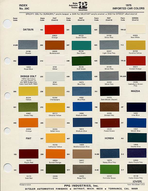
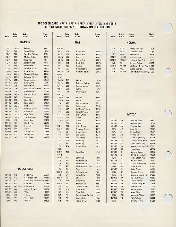
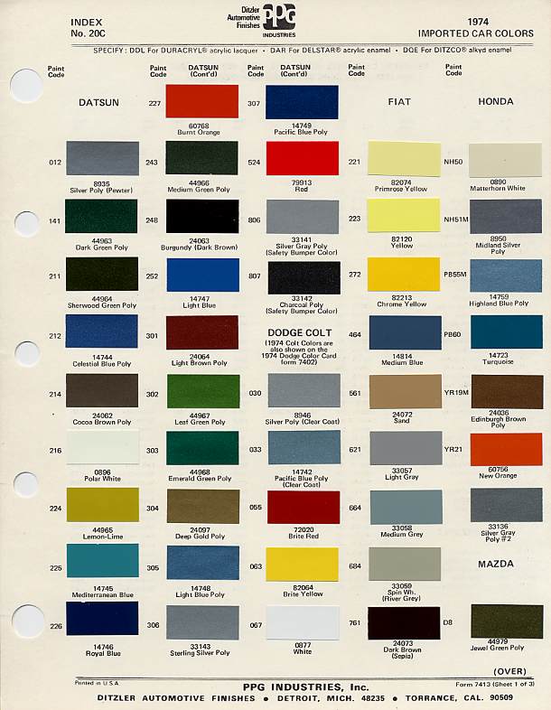
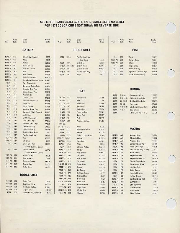
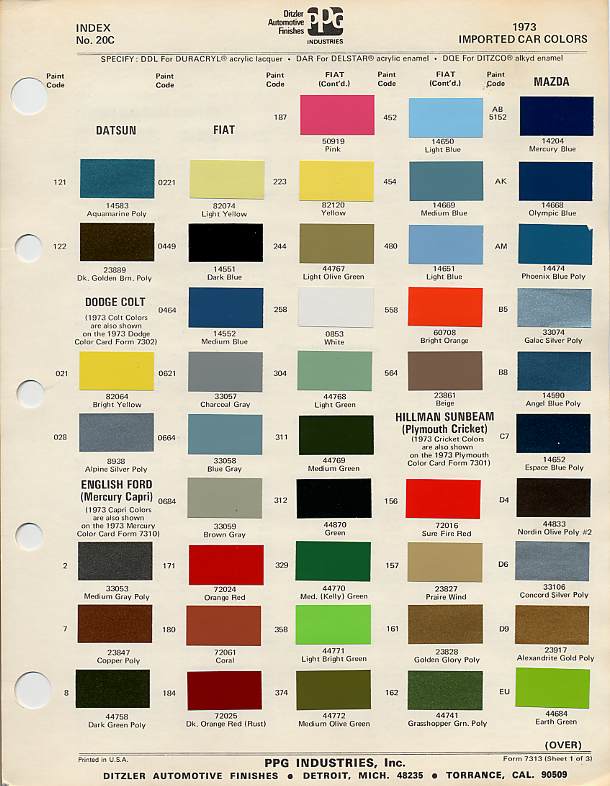
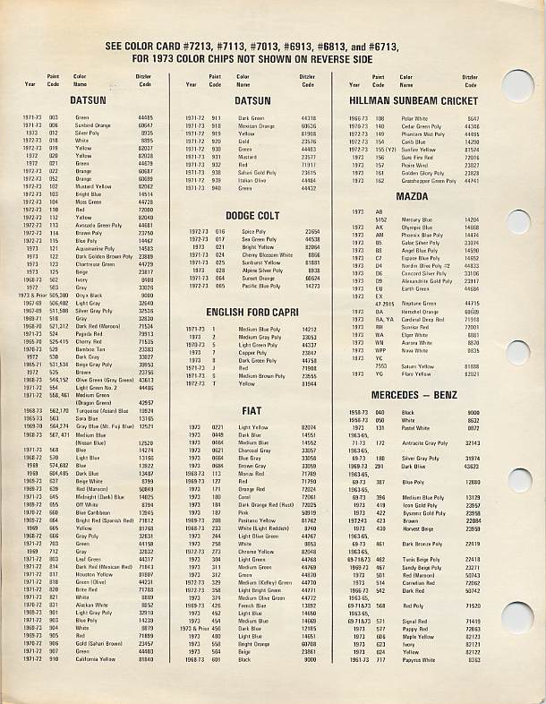
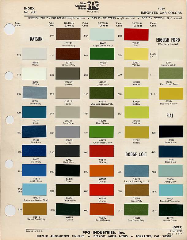
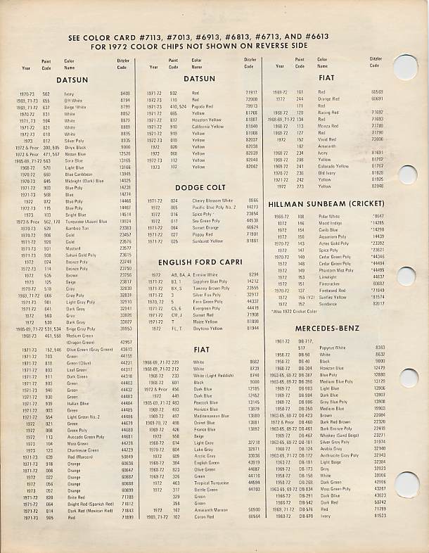
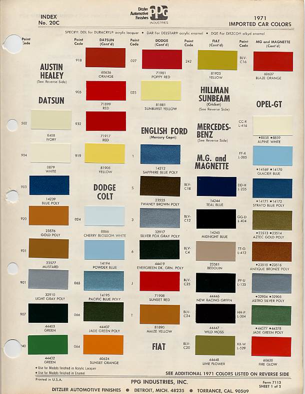
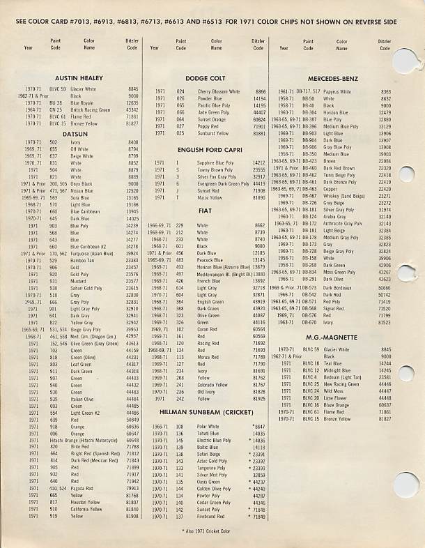
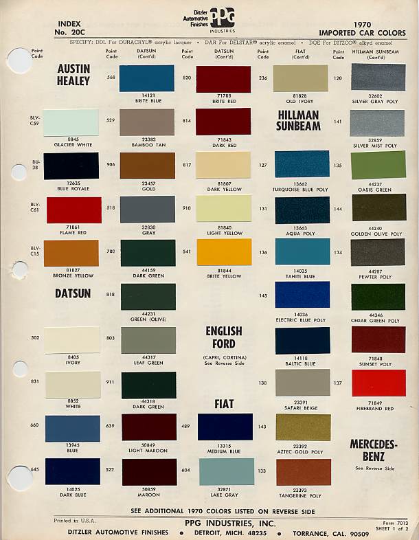
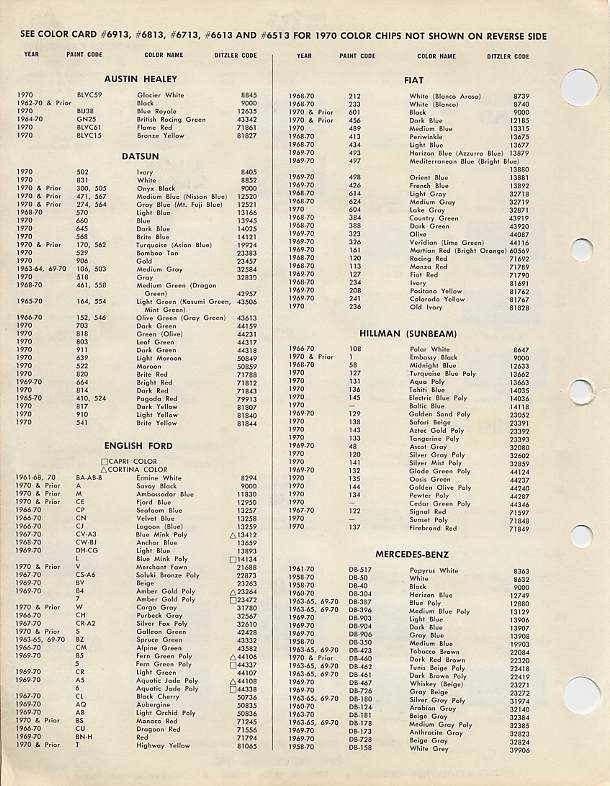
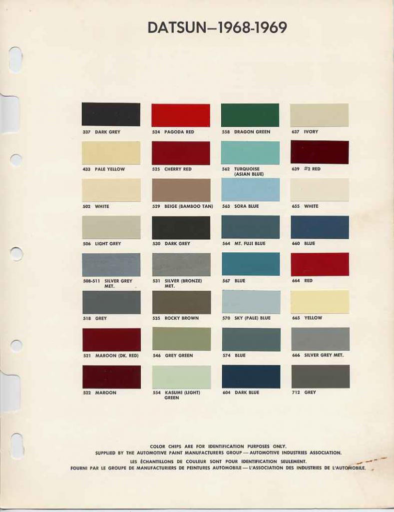
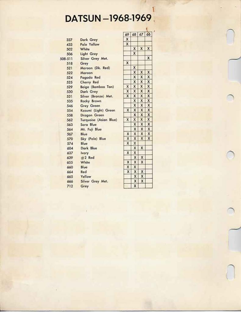
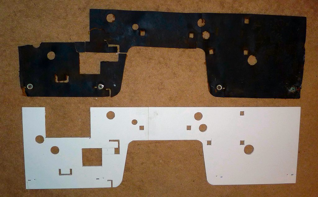
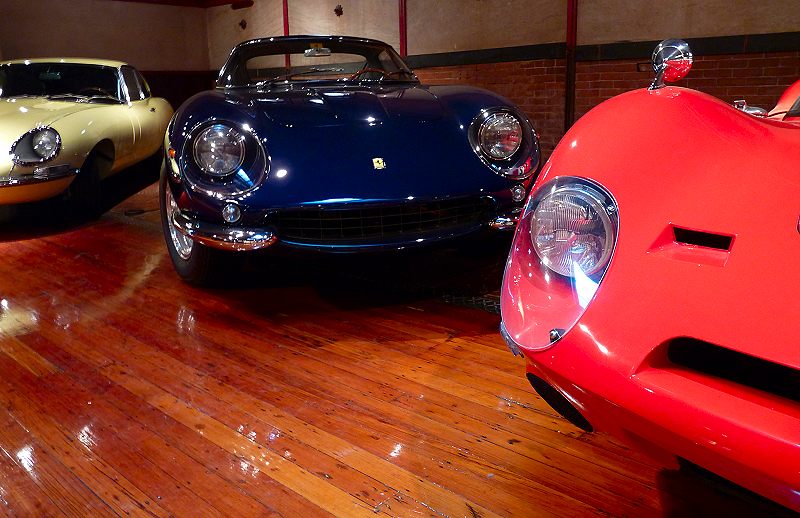


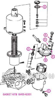
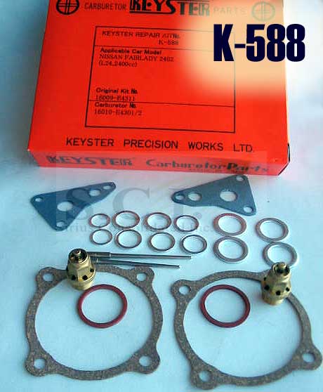
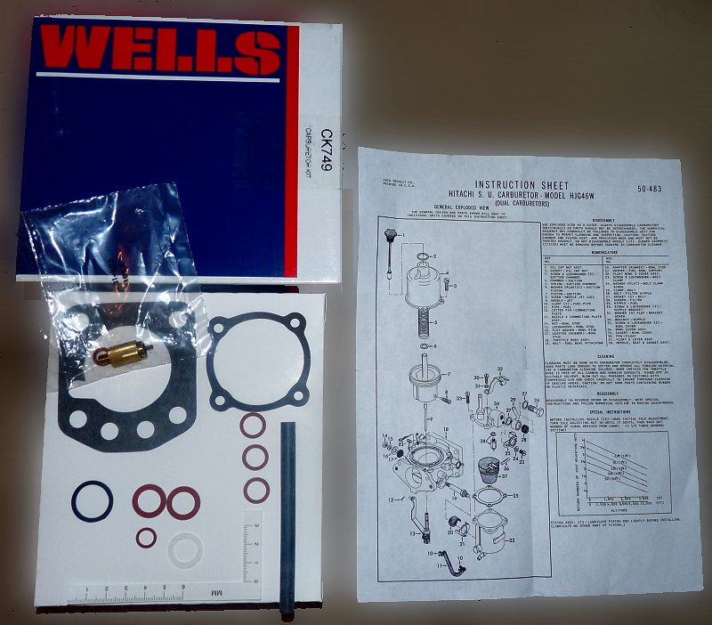

Important Information
By using this site, you agree to our Privacy Policy and Guidelines. We have placed cookies on your device to help make this website better. You can adjust your cookie settings, otherwise we'll assume you're okay to continue.
Account
Search
Configure browser push notifications
Chrome (Android)
- Tap the lock icon next to the address bar.
- Tap Permissions → Notifications.
- Adjust your preference.
Chrome (Desktop)
- Click the padlock icon in the address bar.
- Select Site settings.
- Find Notifications and adjust your preference.
Safari (iOS 16.4+)
- Ensure the site is installed via Add to Home Screen.
- Open Settings App → Notifications.
- Find your app name and adjust your preference.
Safari (macOS)
- Go to Safari → Preferences.
- Click the Websites tab.
- Select Notifications in the sidebar.
- Find this website and adjust your preference.
Edge (Android)
- Tap the lock icon next to the address bar.
- Tap Permissions.
- Find Notifications and adjust your preference.
Edge (Desktop)
- Click the padlock icon in the address bar.
- Click Permissions for this site.
- Find Notifications and adjust your preference.
Firefox (Android)
- Go to Settings → Site permissions.
- Tap Notifications.
- Find this site in the list and adjust your preference.
Firefox (Desktop)
- Open Firefox Settings.
- Search for Notifications.
- Find this site in the list and adjust your preference.