240260280z
Free Member
-
Joined
-
Last visited
Everything posted by 240260280z
-
 If you take the sensor indoors it should read ~2,500 ohms. The problem is that if any of the contacts or the wires to the ECU are corroded or loose, the resistance goes up and the ECU thinks you are at the north pole and dumps fuel in. To ensure the ECU sees the correct resistance, check the resistance with the car cold at the sensor, then check 1' back into the harness at the bullet connectors, then check way back near the drivers left side kick panel at the ECU connector (pins 49and 13) on a 280z harness. All three readings should be very close. http://atlanticz.ca/zclub/techtips/tempsensorpot/index.html: °C °F Resistance -30 -22 20,300 Ω to 33, 000 Ω -10 -14 7,600 Ω to 10,800 Ω +10 50 3,250 Ω to 4,150 Ω +20 68 2,250 Ω to 2,750 Ω +50 122 740 Ω to 940 Ω +80 176 290 Ω to 360Ω
 -
You can rebuild the spare to see what wobbles. Here is a procedure for a zx: http://atlanticz.ca/zclub/techtips/distributorrebuild/index.html You can also upgrade: http://atlanticz.ca/zclub/techtips/distributor/index.html
-
This is probably the problem. The temp sensor wires. The can be removes about 1' back in the harness are two bullet connectors. Remove this "pig tail" and check it with your multimeter.
-
btw I can't remember when Nissan moved the temp sensor to the back of the cylinder head next to plug #6. I think it was in 80 or 81 after the P79 came into existence. If you can't find it in the thermostat housing then check the head.
-
You can swap the EFI connectors from injector 2 with injector 1 to see if the problem is actually the injector or back in the harness/ecu. If it is the injector: You can tap on the #1 injector to try and loosen it with percussion energy. You can also connect a 9V battery to a spare injector connector then push it on and remove from the injector to hit it with a high current. Just hold on for ~ 1 sec then remove as the high current will heat the windings if left on too long.
-
Yeah I had seen this before. Your EFI system is dumping too much fuel into the engine and your car is bogging because of the plug fouling. You have to make sure the connectors to the temperature sensors are making good contact and that the correct sensor is used (there are a few in the thermostat housing. This is the usual problem that causes your symptoms. Be sure to clean the plugs carefully, especially deep in the space between the insulator and threaded body.
-
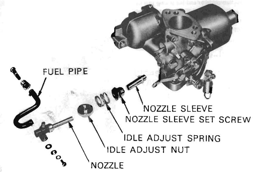
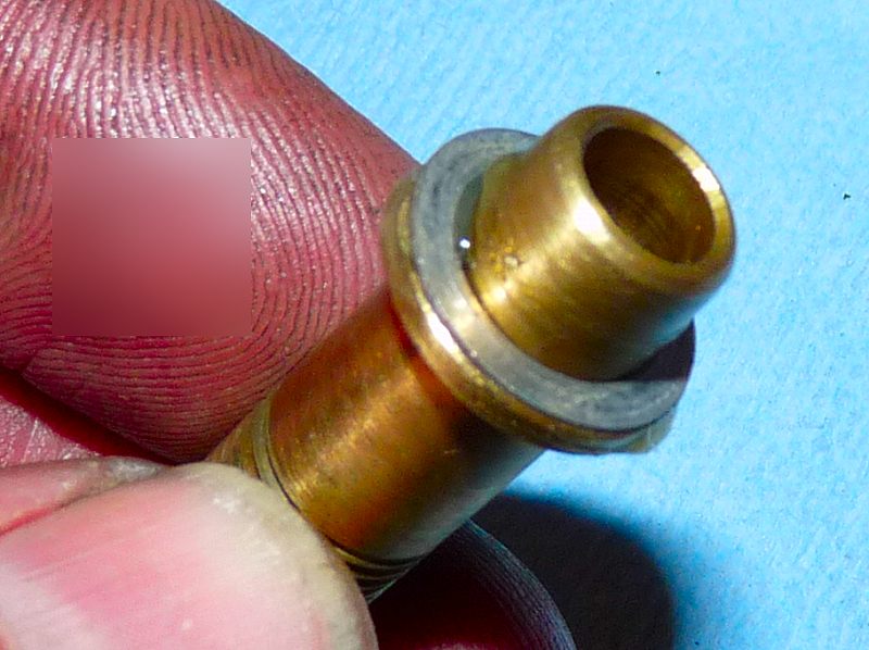
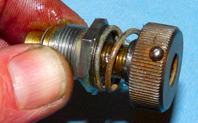
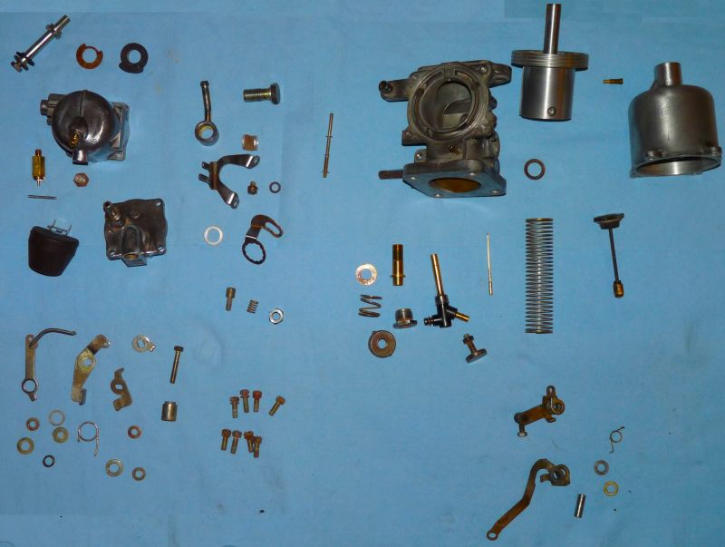
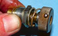
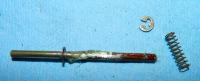
The washers are not shown in this.

-
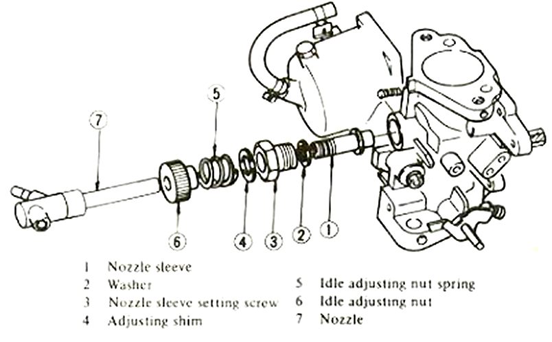
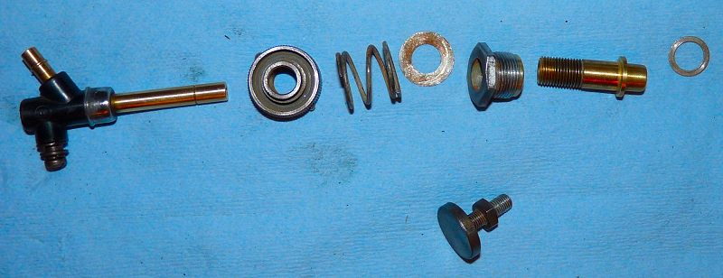
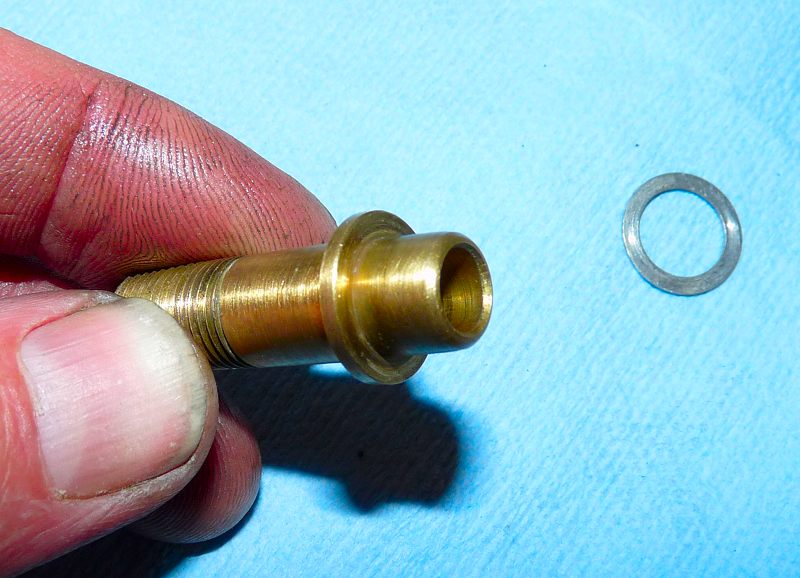
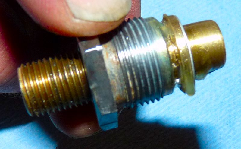
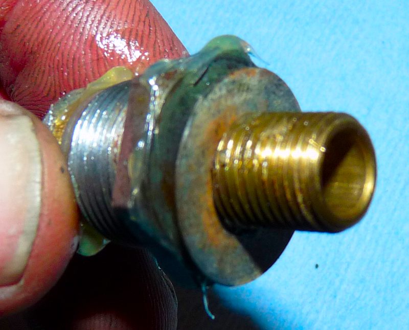
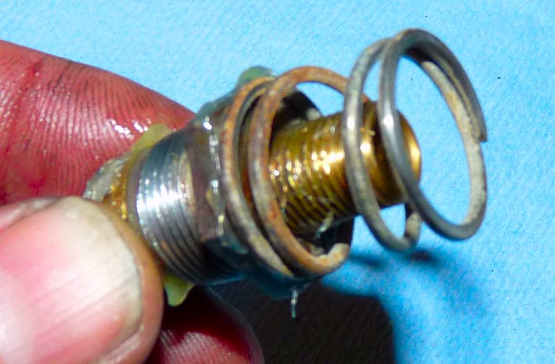
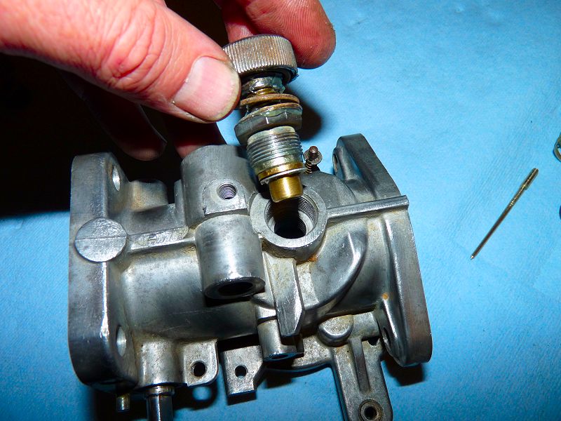
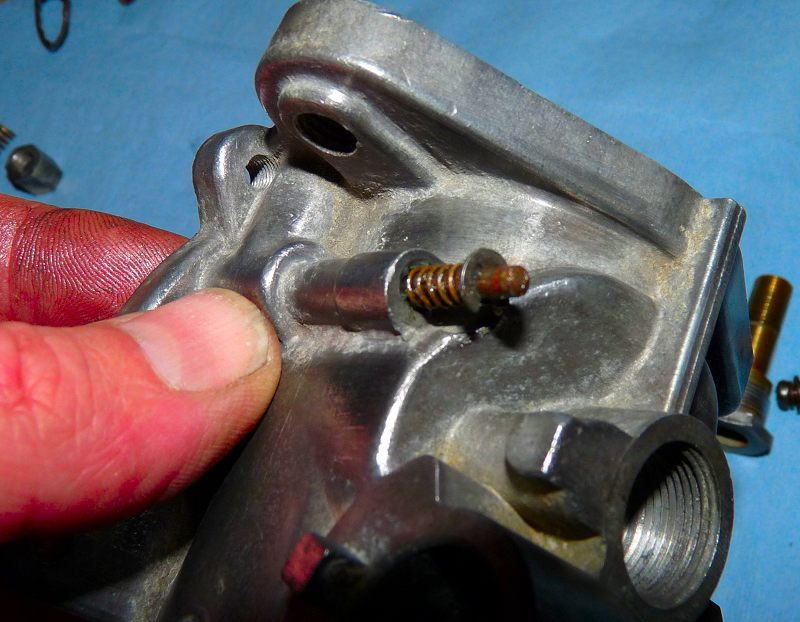
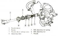
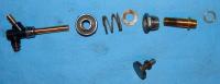
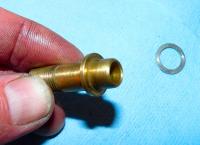
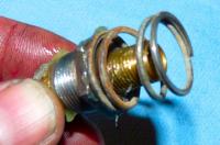
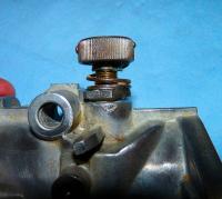
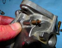
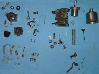
Here are all the parts in relative order. Firmly grasp the nozzle sleeve. (No I am not pink! I used colour enhancement and it enhanced me (fingers) too.) Install the washer on the neck of the sleeve. Some grease is a good thing. NOTE: The washer is on the wrong side in this picture. It goes under the sleeve. Slide the Nozzle Sleeve Set Screw onto the sleeve Install the large washer behind the Nozzle Sleeve Set Screw. Apply grease. Install the Idle Adjust Spring behind the large washer. Apply grease. Install (by screwing) the Idle Adjust Nut. Grease between the spring and the nut will make adjustments easy to do. Here is where it goes at the bottom of the body. Antiseize on the threads is a good idea. Test fit by hand tightening the Nozzle Sleeve Set Screw Here it is in place. As you can see it is not automatically centered.


-
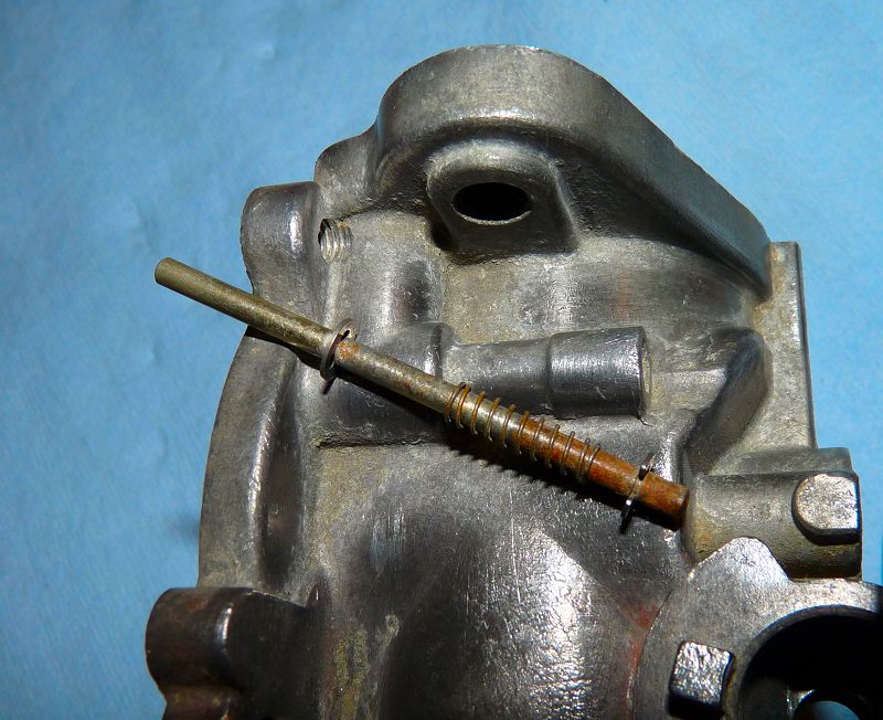
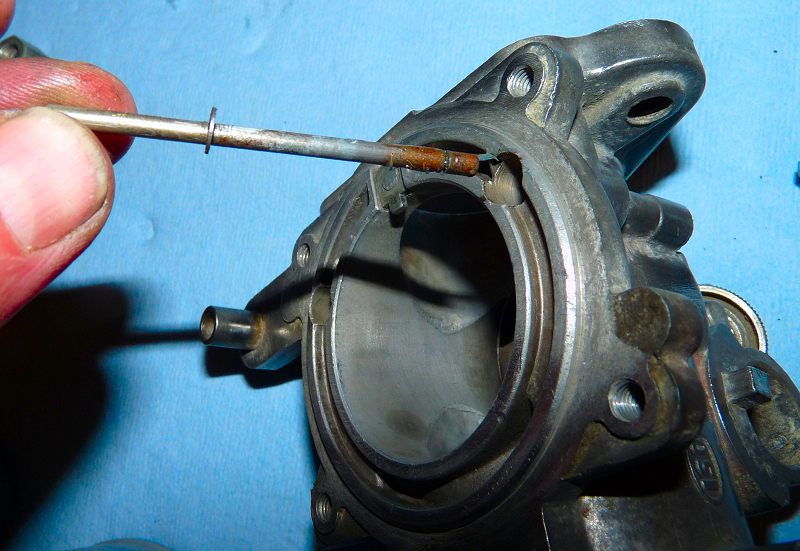
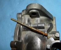
This is easy. Just don't loose the weeeeee itty bitty clips. Needle nose pliers works fine to pull off; and press on the clips. Here is the lifter rod laying just outside of its home cast in the main body. Use a Scotchbrite or sand paper to remove the rust then grease the shaft. Insert the rod into the body. On the bottom side, install the spring then attach the clip retainer. Works fine.


-
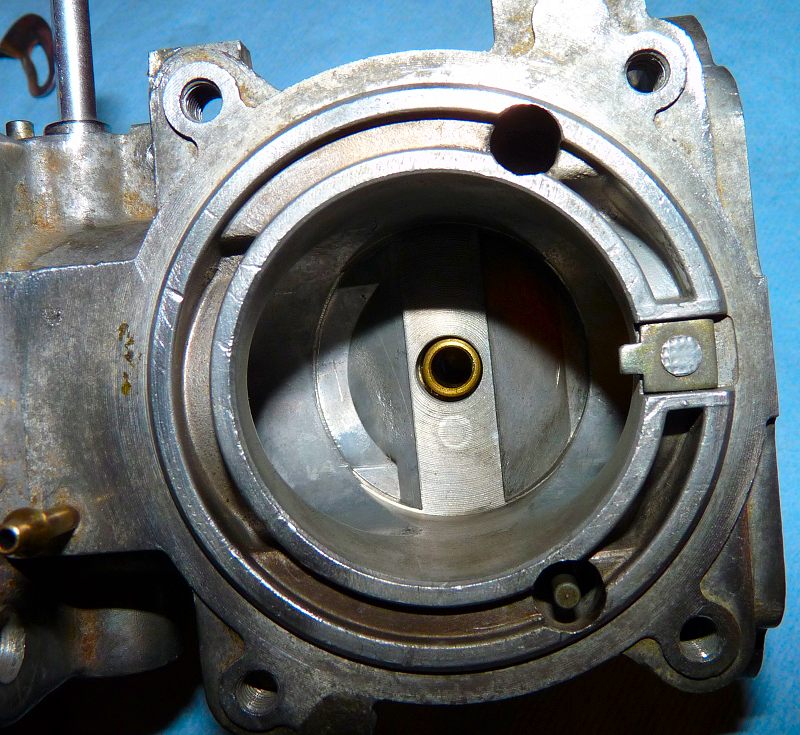
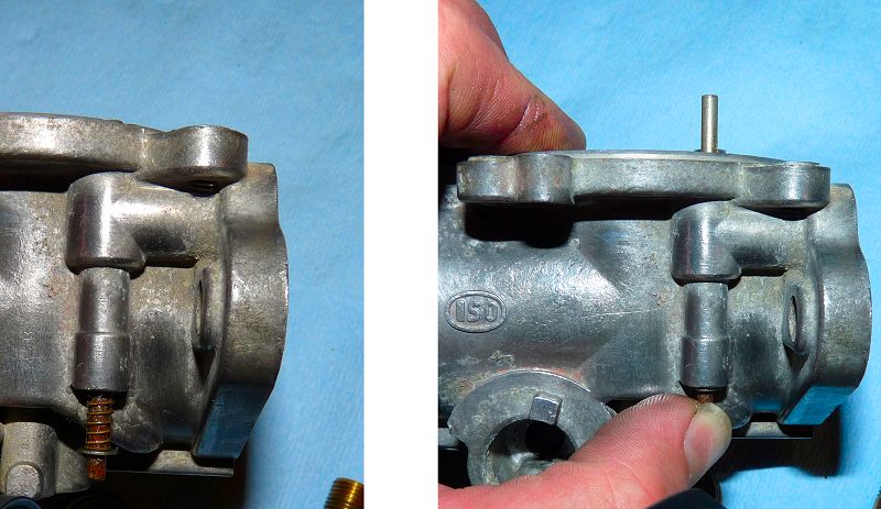
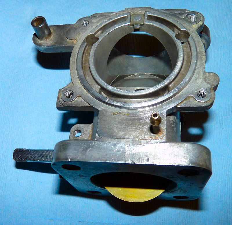
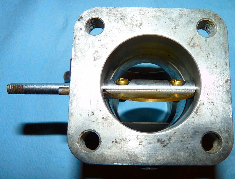
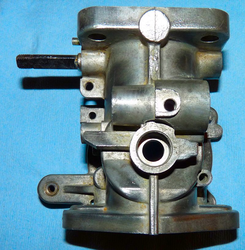
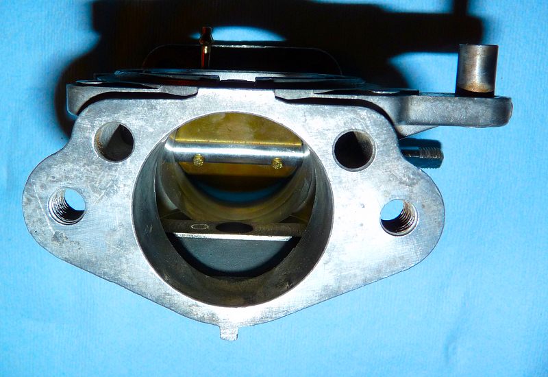
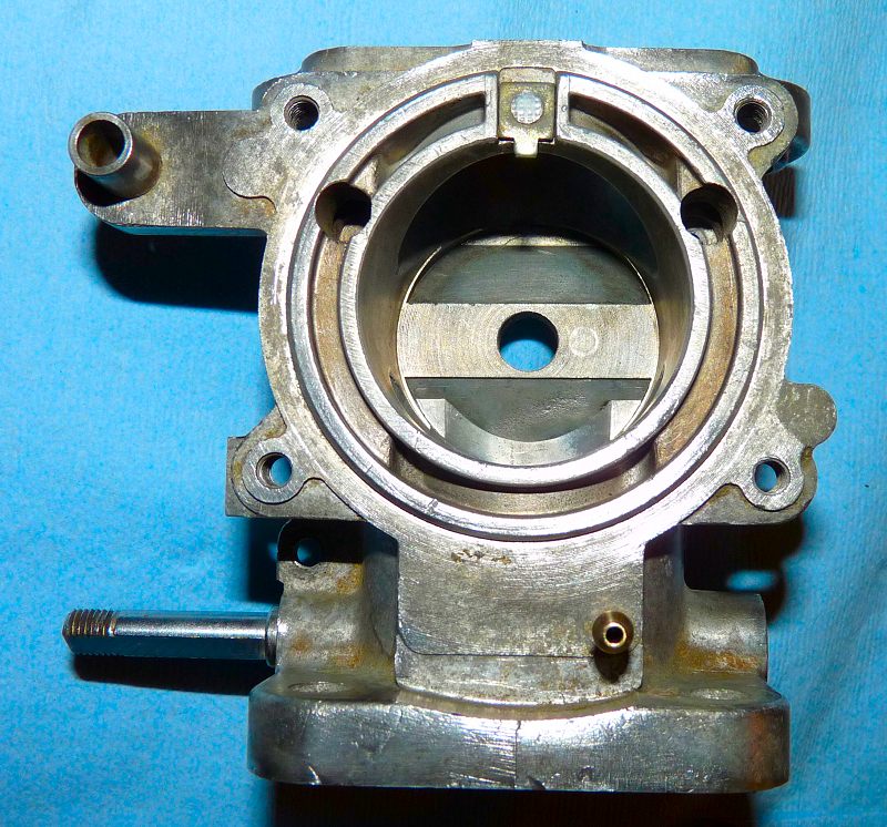
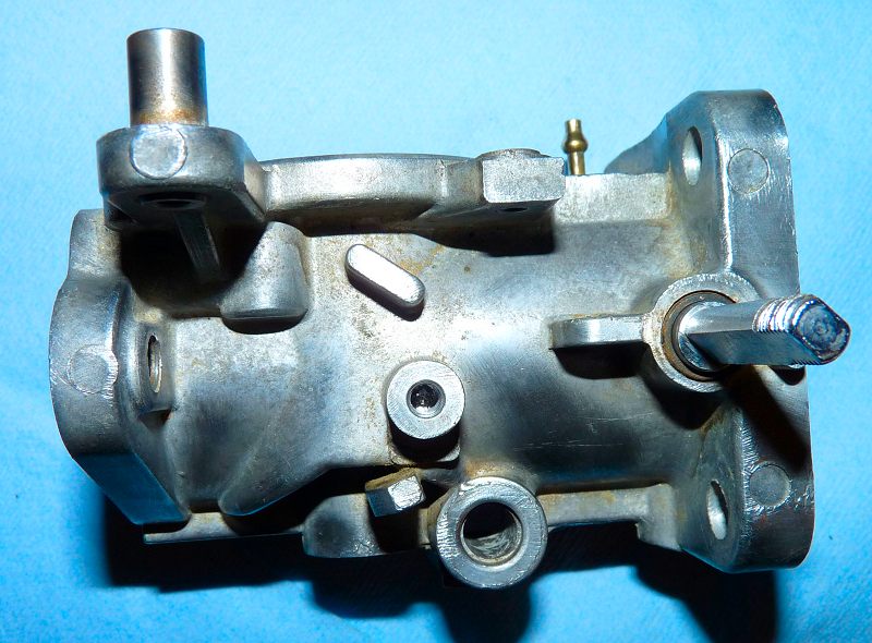
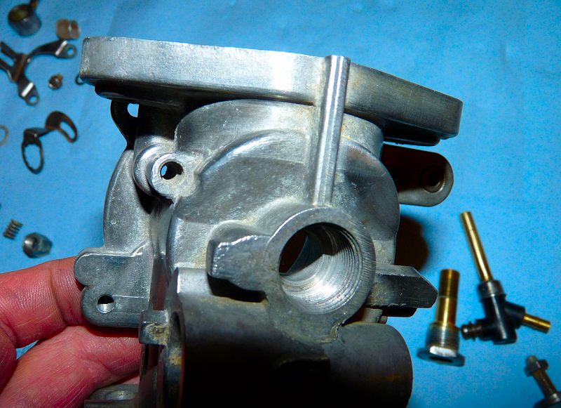
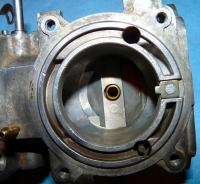
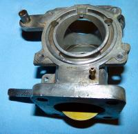
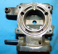
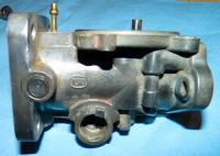
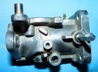
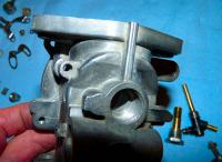
Some Pics of the SU Carb body: Note: I just washed with soapy water, sprayed with carb cleaner, then wire-brushed the outside with a brass wire wheel on a drill The brass bushing around the shaft wears over time and causes a vacuum leak between the shaft and the bushing. You can put a ring of sealant around the rim of hole (but not touching the bushing or shaft) then place a flat round object (like a dime or aluminum disc or rubber disc) over the raised sealant to seal the shaft. Doing this side will cut your vacuum leak to this carb in half. The bushing on this side of the shaft will also leak. Some fittings and linkage that will be installed on the shaft will come close to the body so there is not much you can do to seal this one. Maybe put some concentric O-ring up against the body with some silicone spark plug grease as a lubricant and a very paper-thin washer so that when the linkage presses in, the washer and O-rings will squish and the lube will prevent binding when the shaft turns. The correct fix is to install a new bushing. Here is an idea of what you can do with the right tools: http://home.comcast.net/~rhodes/Tech_Carb_Bushing_Reaming.pdf


-
Lots of photos so it may take me a day or two to get them all up. Here is a step-by-step procedure for reassembling an SU carb. Rip it apart and fear not. I did not take out the throttle valve plate and shaft because of the peening and I am lazy today. (I'll do a step-by-step on modifying an SU in another post in the future where the shaft is filed). Note: I do not have my rebuild kits yet so pretend there are new gaskets
-
Hmmm seems like it is still fuel.... but with your exhaust query. Can you start and rev and see what comes out the tail pipe? What do the plugs look like? If the ECU was not metering the fuel correctly, your plugs could be pitch black and fouled to hell. Usually the culprit is the wiring to the temp sensor that resides in the thermostat housing. Connections at this sensor and ~ 1 foot back into the harness are where to check. http://atlanticz.ca/zclub/techtips/runningrich/index.html
-
Probably the fuel is varnished. Drain the tank and see what comes out. (There is a drain plug in the bottom of the tank). It could also be rust clogging the lines. Put a frame fuel filter before the pump on the low pressure side to monitor. http://atlanticz.ca/zclub/techtips/fuel/g3filter/index.htm
-
-
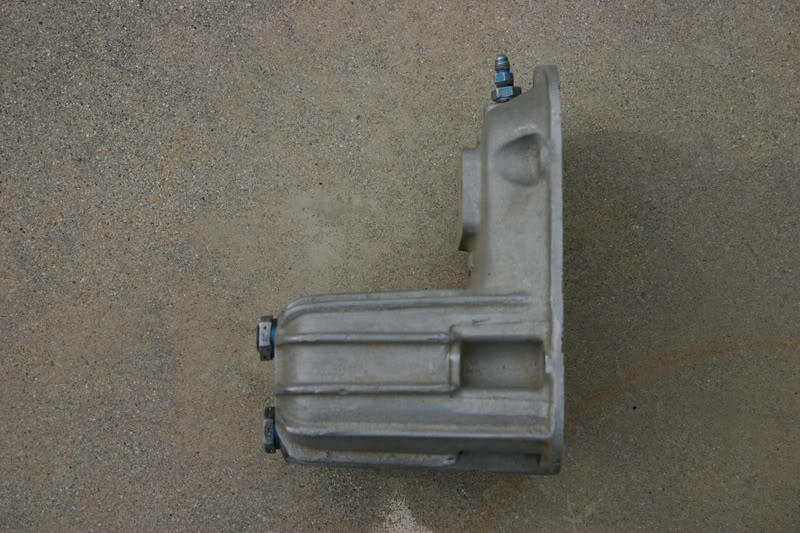
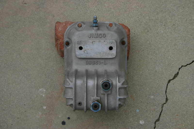
For my current plan: Control: The signal to energize the relay would come from the ignition circuitry. When the key is off the energy draw from the battery would be off. As well this control signal would also go through the oil pressure switch so even with the key turned to on and the car not running, the pump would not run. The pump would only run when cranking AND oil pressure OR when running AND oil pressure. It may have a switch in series for theft protection. Power: The pump would draw from a separate circuit that is fused and is connected as electrically close to the battery send and return as possible. It would also go through the main contactors in the relay. OR Drill out a hole in the Maxima N47 head where the fuel pump goes then die grind the triangle.

-
-
Small flat screwdriver or drift and tap at a tangent to the piston. The drift or flat screw driver has to bite into the ring gap.
-
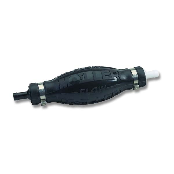
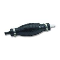
Well I am fond of the clacker as I love mechanical technology but I never liked it when it lost its prime. I was always thinking that a bulb primer by the tank would have been good addition for emergencies with its one way valve to boot. Hey I guess you now know I used to run outboards in the Canadian back woods .
-
Thanks Steve! That is good info.
-
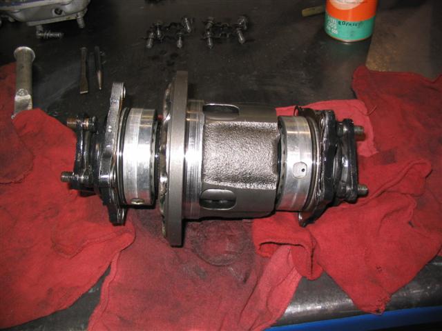
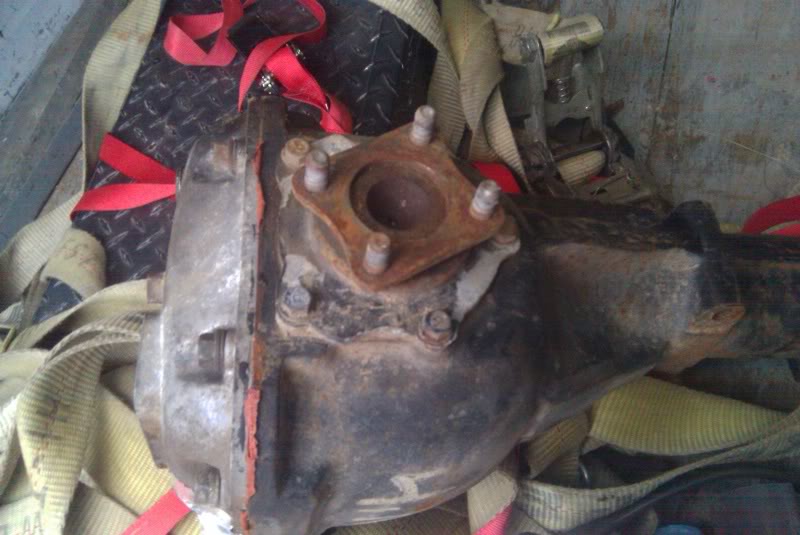
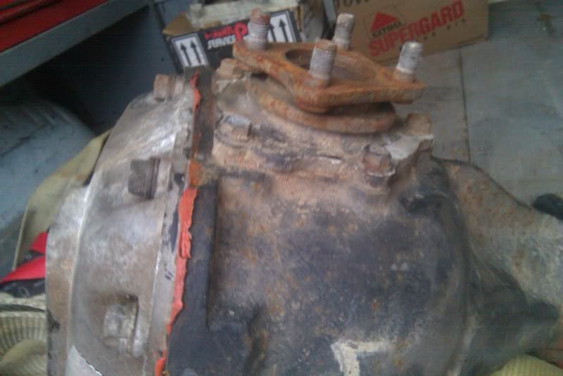
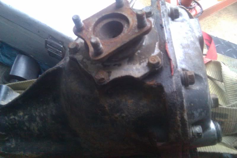
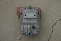
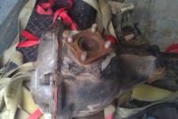
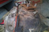
Exploded View R190 Differential R190 Parts List R190 LSD 3rd Party back cover with extra capacity and cooling fins Photos from the net showing larger side flange on "pumpkin" Elusive bearing part: NTN 323/28C Nissan 09022-0010P All bearing part numbers: Part 23: Taper Roller Bearing 38120-61000 (Timken 32307) Part 24: Pinion Bearing Front 38140-A0100 Part 25: Pilot Bearing Front 38335-A0100 Part 32: Taper Roller Bearing Side 09022-0012P Part 38: Side Flange Pilot Bearing 38440-A0100 (Timken 107WB) Recommended Rebuild Shop: http://www.gounitrax.com/


-
I am considering going electric on the restoration as I will otherwise have to drill out the N47 head to allow the clacker arm to enter the head. (At least the stud holes for mounting the pump are there and they are threaded). So rather than do this, I am considering the following: 1. Fuel Pump Relay controlled by 12V signal from a pressure switch on the oil sensor 2. Fuse and 12V lead to pump motor via the relay 3. Maybe a cut-off switch to the relay control for security. Any recommendations? Is 280zx oil pressure sender/switch same thread as on l24 block?
-
Redline MTL worked great in my 280z with 82 5sp transmission.... but not great in my S2000. Honda manual transmission fluid works great in the Honda and it is inexpensive.
-
Only folks on ClassicZCar.com can see these "Technical Articles" so you are ok for now Off to ACE again for another project. Hey, I'm the guy who made front bearing drifts from $2 cast iron pipe fittings.... I must have Russian blood in my veins.
-
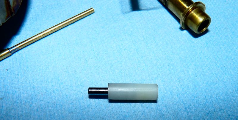
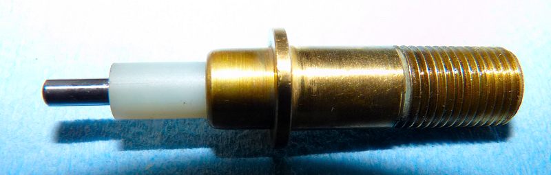
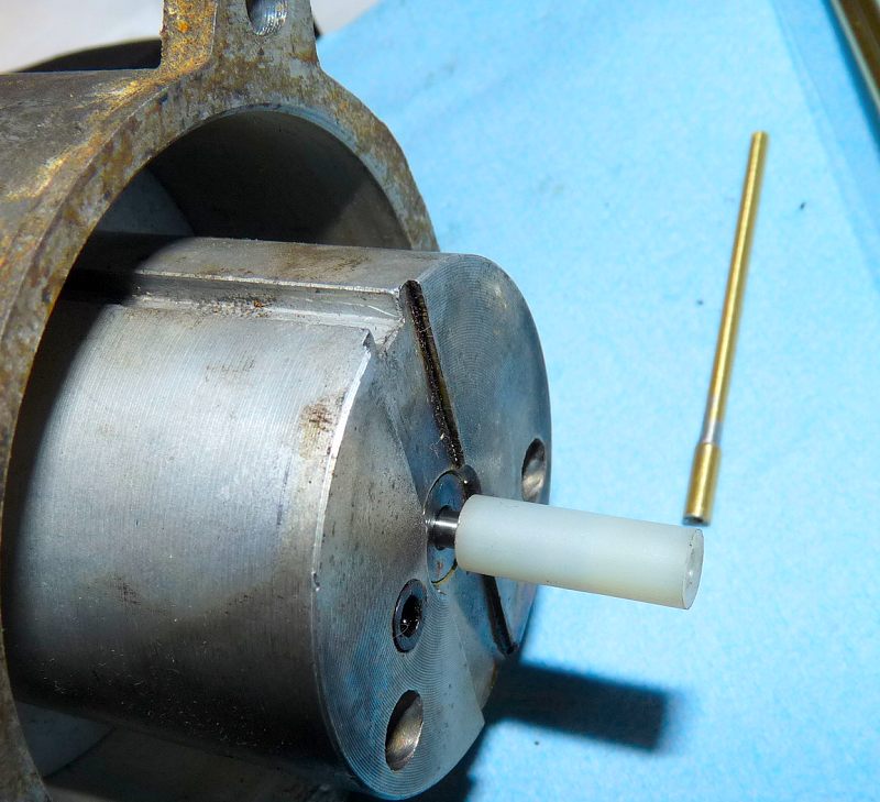
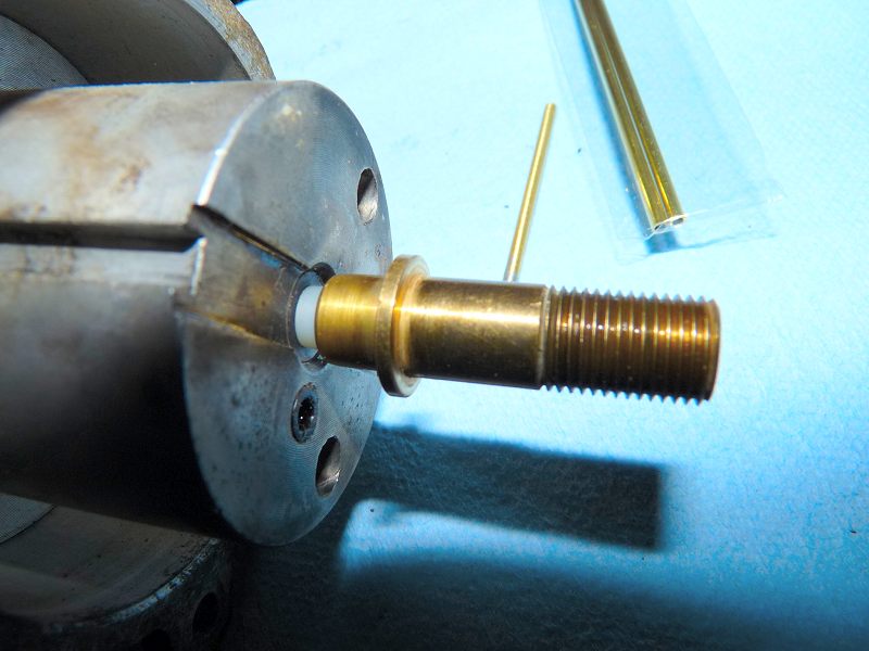
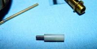
Mark II is $0.43. It should be better than Mk-I because it aligns the nozzle guide directly rather than aligning it through the nozzle. This reduces the error/slop that exists between the nozzle and the guide. It consists of one 1/8"dia X 3/4" metal pin and one 1/4" dia X 23/32" long nylon spacer with 0.110" ID. Just tap the pin part way into the nylon spacer and that is it. Mk-II Parts: Steel Pin and Nylon Spacer The nylon spacer fits in the jet nozzle guide. The steel pin fits into the piston's needle hole. All three parts aligned Ace parts 44237-C (nylon spacer) and 58011-K (steel pin) Now to finish a front differential mount to put Ron Tyler's design, complexity and cost to shame.


-
I was looking in the fuel hose section of Pep Boys last evening and noted some larger diameter PCV hose that is fuel rated. It looked like it may work in place of the 3/4" between the filler neck and the evap. tank. For hydraulic hoses. It is a good idea but I could only source high pressure hoses that had one or two internal wraps of wire that made the hoses bigger than the low pressure ones recommended above.