240260280z
Free Member
-
Joined
-
Last visited
Everything posted by 240260280z
-
 If you do not use the vacuum advance and set initial at 19 degrees then total will be 36 degrees (19 degrees static and 17 degrees mechanical). This woks nicely for many. Starting at 19 degrees advance may buck the starter a little.
 -
Does not look familiar to me. I would guess it is an after-market part. Looks like a relay with a fuse.
-
I'll be in Bermuda for 2 weeks. Any Z owners living there or visiting?
-
The 1 into 3 manifold is a partial balance tube in itself.
-
Speedo cog may come out with a bit of penetrating magic (50/50 mix of ATF and acetone) and a twirl with a pipe wrench. Some heat on the aluminum surrounding the cog is another method.
-
I think that is a great idea. Passini hates balance tubes and states they do more to adversely affect performance (on webers).
-
Cut two flat pieces of stiff rubber. Cut out the holes, lay one on the other then use polyurethane sealant to join the edges.
-
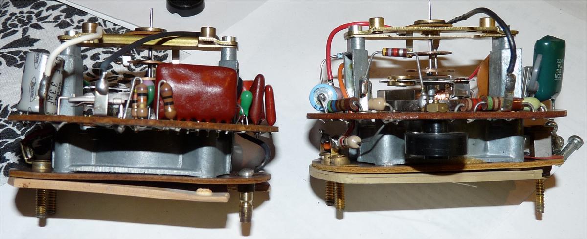
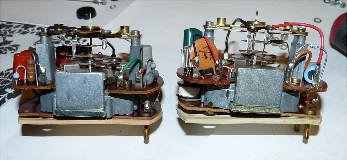
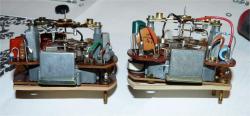
Yes, they are both trimmer pots. The 280z is the conventional circuit board mount but the 240z looks like a standard potentiometer on the bottom (black) that is mounted to the board by the shaft (brass nut). These appear to be turned from behind through a hole in the case.
-
Great detective work! Resolving the bugs one at a time.
-
I don't understand the reason why people install such audio systems? Given the noise levels in a moving car , the terrible acoustic surfaces/shapes, and the confined space, it always seemed like a hopeless effort and waste of money.
-
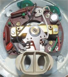
It looks like the top assembly that holds the needle bearing has drop tabs connected to springs may be "user-rotatable" too. I have never played with it so I can't say for sure.
-
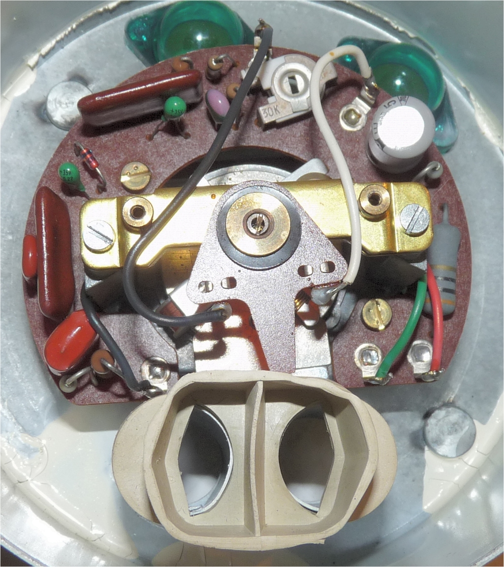
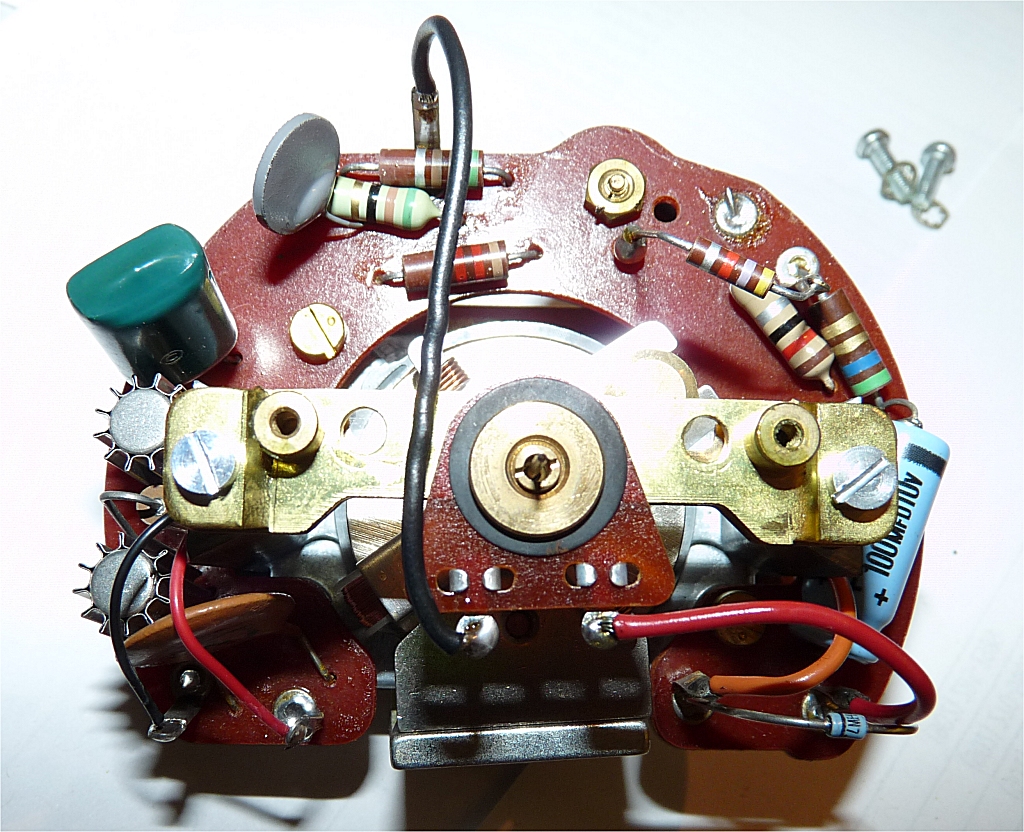
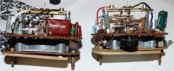
Having problems putting images in line??? Below is a 280z tach module on left and 240z tach module on the right. The adjuster is at ~ 12:30 "o'clock". You can access it from the back of the tach's "can" enclosure. The access hole is between the two lamps.

-
There is a calibration adjustment on the tachs.
-
Same issue that Johnc and I discussed a few days ago. Have a look at the post with all the meter photographs here: http://www.thesamba.com/vw/forum/viewtopic.php?t=508798
-
Those are great tools! You can accurately read rpm as well as advance the timing light to read the mark nulled to 0 on the scale at the damper pulley. The cable is long enough to read rpms from the passenger compartment while driving ... works great when also reading the O2 in the passenger seat in real time road tuning.
-
Flog that horse:
-
My understanding is that at cruise in 5th on a highway, the throttle valve is not opened greatly so there is a very high venturi effect near this partially opened throttle valve. This is when max vacuum advance is in play. Moving towards WOT causes the venturi effect to drop off a bit until the rpms are high enough to match the localized flow in the cruise area.
-
Sounds like fun!
-
Love the licence plate screw history. You are first class!! Glad you made it home safe and sound. I hope I can get your magazine spread!!!!!
-
I may be in NJ area in Jan. CO I'll do my best to visit my old buddy and state neighbour.
-
Sort of... that is the reality of what we are adjusting however, if you want to try to get an approximate bench mark at least ; one that many can use, it will be difficult. For example if a procedure states to set the RPM's to 850 at idle and one person's rpm tester was not the same as another's then it would be difficult to achieve the desired result. I would expect a better level of agreement between $50 test instruments with flow numbers on the case. I now have two flow testers my old EMPI and new STE that I will soon compare for bringing a third into the comparison.
-
This is an FYI just in case people try to set the same flow number at idle for stock cars, there is no accurate way to ensure the number read is correct.
-
Dang that is horrible. What a bum to sell you a head with so many problems. I thought that store was doing a good service for the Z community .... what a bum.
-
it's Steves 260z... I visited with him and we had a blast tuning it. The PO left us scratching our heads/ cursing many times....for example the locking nuts on the rocker (lash) adjuster pivots must have been 100 ft-lbs... some were so tight it took two of us on a wrench to loosen. The vacuum advance canister had a leak so there was no vacuum advance; only mechanical. This makes the 32 degrees observed [AT IDLE] even more difficult to accept.
-
For the record, I had the opportunity to test an EMPI synchrometer against an STE synchrometer and the readings on each were different. I do not think they are calibrated well. The EMPI read higher at idle.