240260280z
Free Member
-
Joined
-
Last visited
Everything posted by 240260280z
-
 Even leather sun visor covers! items in datsun store on eBay!
 -
Car parts manual site gives: RIVET-PLASTIC,BLACK 90909-E4100 qty=16 for 240z interior plastic panels RIVET-PLASTIC,BLACK 90909-E4100 qty=8 for 240z interior tail light access plastic panel RIVET-PLASTIC 79909-E4100 qty=8 for 240z exterior tail light/license plate metal finisher panels RIVET-PLASTIC,BLACK 90909-E4100 qty=10 for 240z interior hatch vinyl finisher panel (air vent cover) for 260.280z RIVET-PLASTIC M5 90909-E4100 qty=6 for 260z/280z exterior tail light/license plate metal finisher panels 08510-52097 from 7702 qty=4 RIVET-PLASTIC (BLACK 90909-E4100 qty=14 for 260z/280z interior plastic panels RIVET-PLASTIC BLACK 90909-E4100 qty=16 for 260z/280z interior plastic panels
-
Check the hoses and connections in the back quarter above the tank were the evap. system is.
-
inline engines work best with side draft carbs
-
Dang I was just in Panama before Christmas looking for Z folks and parts. I'll definitely look you up next time and hopefully take a spin in a Z with AC!
-
I just dug deeper to find my source: 78 FSM says to set TVS to change at 4 degrees (idle breaks) and 34 degrees (WOT makes) It also say in item 8 on page EF-41 to set the idle to 1400 rpm then rotate the TVS to just make/brake at that point.
-
I think it is in there somewhere in the print...could be in the EFI bible or in a graph. Page EF-56 in the 77FSM says to adjust so that the idle contact opens after 7 degrees of throttle plate rotation. I'm happy to help.... once you dig in a bit more you will be an expert. I remember doing what you are now doing
-
Yeah if you just follow the instructions it will work out but if you go the step further to understand the path and what is being sent along it then you will intuitively know. The toughest part of electrical testing is translating a nice pretty and compact schematic to a dirty complicated snarl of wires. The one good advantage you have is knowing that most electrical problems with a Z are at the connectors. If you simply disconnect the battery then do a search and destroy mission of finding every connector, inspecting, cleaning/burnishing (remove corrosion), applying a contact cleaner, applying dielectric grease (water proofing) then reassembling; you will fix a lot of problems and many waiting to happen. The connectors in the steering column (remove plastic) and the many down around the passenger foot well (even under the carpet) are important to clean too.
-
Look on the inside in the foot well area where no sun has shone or under metal where it over lapped other painted metal. In my layman terms: 905 is a tomato red; it has a slight orange tint. (905 Red)
-
I hear you. I am making shelves for my garage (shed when you speak of this in front of my wife) and love the smell of the cut wood. Lining up the table saw was fun too. The youth will come around...it is just a dark time in our history now To affirm this I just got an email from two "young-uns" who responded to a "lathe wanted ad" and wanted me to go splits on a small metal lathe.
-
This is worth following as well: http://www.atlanticz.ca/zclub/techtips/electricalconnections/index.html
-
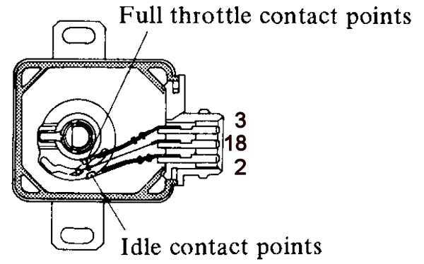
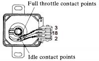
At the TVS, just pull off the harness connector and plastic cover. You should be able to see the centre vane (18) bend from the idle contact (2) and to the wide open contact (3) as you open the throttle by hand. Just measure the corresponding points with the ohm meter touching the connector terminals on the TVS. When the centre vane touches the idle (18-2 continuity) , you should have continuity between these two contacts, when the centre vane is not touching either you will have no continuity. When the centre vane touches the WOT contact (18-3 continuity), you should have continuity between these two contacts. The FSM is well written for mechanics to quickly troubleshoot at convenient locations however the fundamental method of trouble shooting source-sink systems like this is to measure (collect data) at the source (TVS), then continue outward along transmission line (wire harness) that carries the data (continuity changes)............ so you collect data at the TVS (visual observation of contacts making braking and corresponding continuity changes at the terminals on the connector) then follow these same signals along the cable to the sink (ECU connector)
-
The Test 1 is for measuring continuity at idle. The contacts are numbered 2 & 18. The accelerator pedal should be at idle to measure continuity (low resistance near 0 ohms). The referenced drawing for Test 1 is figure:EF-35 on page EF-25. If you get continuity at the TVS but not at the ECU connector pins (with the TVS re-connected and the pedal at idle) then the harness connector probably has corrosion at the TVS).
-
Makes you want to buy a lathe....even a wood one.
-
Looks fantastic
-
I'll look it up. what book are you reading? (Where can I find EF-37)? What year 280z do you have?
-
This may help: http://www.atlanticz.ca/zclub/techtips/tps/index.html
-
I used to have access to a Low frequency HP spectrum analyser that was used to measure noise and vibration (in 3 axis). I think they may have been used something similar (but analogue) at the time. FYI here is a brochure with a photo of the digital data acquisition and analyser being used in a vehicle http://www.wmich.edu/mae/research_labs/noise_vibration/pdf/HP_analyzer.pdf Alan mentioned torsional loading so some load sensors may be placed on structures...as you said it would be nice to know what they measured.

-
It is a funny spot. I remember cringing when the muffler shop guy hit it back in a little with a hammer to help the exhaust from hitting. Now I try to do all of the work myself. Maybe the exhaust heat will anneal it so that when I strip down and restore I can re-form it easier .
-
Early wiring for 240z If you ever upgrade, here is a useful walk through http://www.classiczcars.com/forums/tech-pubs-howto/47191-tachometer-swap-280z-into-240z-series-1-housing.html
-
I have 12" wid X 15" BBS RS's and just picked up some Classic Datsun ZG flares from Kijiji I'll post here when I am at trial fit stage. If no fit then Z force productions will be the next step.
-
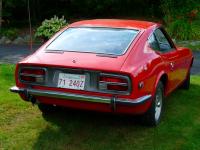
Thanks Alan, I'll dig into the Kaku-U content in the archives. I found this picture of the same car/location:
-
Now I will never be able to look in the foot well and not see "A little cupcake goes a long way" Nice work.
-
I tried to install the flywheel and pressure plate evenly with symmetrical tightening /torquing of all bolts in steps to ensure correct alignment and fastening. I still had to slam the transmission harder than I wanted to make it mate (after ~ 20min of trying gentler methods). I wonder if the problem is at the fly wheel area or up at the nose where the new bushing resides.
-
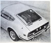
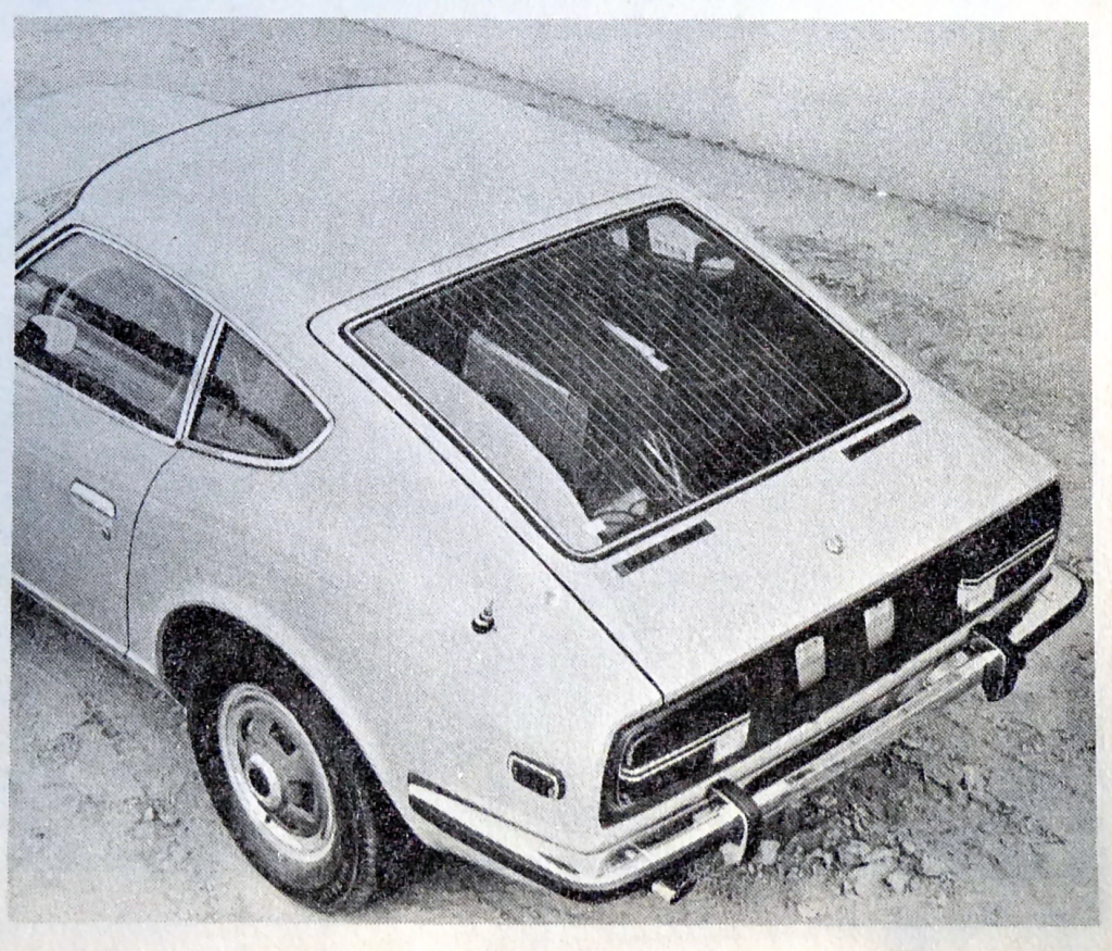
I noticed this pic in an old book I had (Petersen's Complete Book of Datsun). It did not have C pillar emblems, seemed to have a data collection box and wires to sensors in the back, and was on dirt next to a building. It reminded me of a photo location I had seen before so I did some digging to try and figure out where and what was going on. I think this is the same car and location....from one of the 1969 field testing runs: This looks like the same car with the data box in the back: Here it is again on the left (with, what appears to be the same box in the back) So what was in the back? ...and what about the defrost wires in the window in the top picture? This seems to be the odd ball outlier? Could the other photos not pick up the wires or was a different spare hatch fitted during the testing? I had assumed the defrost wires came later.