240260280z
Free Member
-
Joined
-
Last visited
Everything posted by 240260280z
-

-
That is normal. It is on all the time and does not consume much power at all.
-
My 3 fav upgrades: Larger front sway bar ZX distributor (refreshed) Smaller steering wheel btw I have upgraded ~ 5 cars to 280zx distributor with no failures.
-
Kats, were there waiting lists in Japan to buy Z's when they were first manufactured? Here in Eastern Canada, a gentleman, for whom I am restoring his car, had to wait one year to get a Z. He wanted it in 1970 but it was not until April 1971 when he could get one.... and he bought it in British Columbia as he was still on the waiting list in Eastern Canada.
-
I certainly don't recall those diagonal groves when I rebuilt mine years ago... but my memory ain't so good.
-
Follow up. Tach works great. Here is a clever use of spoons I found on the net: How to remove the needle from a tachometer.
-
There is a member who may be selling a shell in San Diego who just posted yesterday.
-
btw my 77 has two movable pistons in each cylinder. Earlier Z's only have one: http://www.blackdragonauto.com/pdfcatalogs/pdf/ZR/0053.pdf
-
Rock Auto Shows Dorman 96618 and Bendix 6672 as a fit for the following: NISSAN 280Z (1977 - 1978) For early 280z's it gives: Doorman 96855 & Bendix 66673 NISSAN 240Z (1972 - 1973) NISSAN 260Z (1974 - 1975) NISSAN 280Z (1975 - 1976) Looks like different parts after 76 and you seem to have an early cylinder. What month is your 77?
-
Hmmmm not sure now. I thought it was for early DCOE's throttle shafts but I can't find it in a diagram, Looks a bit like the seal on my Coleman Stove.
-
You should use the "garage" feature for members and add all of your cars. I like the orange rear turn lights
-
... I will have 125's freed up once I get the 120's so hang tight.... it sounds like symbiosis. I read that more air corr. does move the main's rpm start point out. Good to see it happen in your experiments. I think the only way to counter balance is with etube changes and fuel levels...but at 25mm down in the well, the fuel won't come on any earlier without overflowing the bowl...so e-tube is your only trick left. I also read that a rule of thumb is 0.50mm between Fuel and air.... I also read 0.6mm too . So for 125fuel you will need 175 to 185 air. The 180 may be worth re-trying with the 125's. Check your AFR holding at 4000 to see if you have too much or too little fuel jet. Check your AFR holding at 6000 to see if you have too much or too little air corr. (get an assistant for this in third or do it in 2nd on a long gentle hill)
-
Nice stuff Wade!
-
Great report! What was your AFR at 4k and at 6k? Last weekend when I measured and recorded A/F as my brother drove, his driving commentary matched the A/F ratios I recorded: Going with bigger idle jets and lower AFR made the car "sluggish"...similar to your commentary above wrt 32 vs 30mm. I am wondering if you can play with mains and air with 32mm chokes to see what happens on each side of 13AFR between 4k and 6k. (120f & 180a vs 130f and 170a)
-
sell as a shell for a racer
-
WRT leak: PCV and hose installed under the manifold?
-
2nd opinion: ignition. Look at your plugs too,
-
From what I read, the "pin vise" is used to drill by hand. The holes will not be as precise as factory but it should allow for very close approximations. I also read that one must be careful to keep the solder off the mating surfaces to ensure a good seal.
-
The air dam makes the car more stable at higher speeds and who will look waaaayyyy down under to see a few nicely placed holes? If it was concourse car then maybe it would make a difference but for looks and performance, it is a great addition in my opinion.
-
Here is what actually happens when connectors corrode: This is a fictional circuit that has a fuel pump connected to a battery and a connector in the circuit Notes: ignore alternator 12.8V battery V is rounded up to 13V for simplicity The battery's job is to maintain +13V. The amount of current drawn is determined by the load on the battery, in this case the only load is the resistance of the pump (1.86ohms). (pretend the wires and connectors are perfect conductors and have no resistance) So the resistance of the pump is what "draws" current from the battery. In this example 1.86 ohms draws 7Amps at +13V (Ohm's Law I =V/R = 13 / 1.86) Now a poor connection is introduced in the connector and it's resistance increases by only 1ohm. The battery's job is still to maintain +13V. The amount of current drawn is still determined by the load on the battery (which has now increased by 1ohm) (1.86ohms + 1ohm= 2.86ohms). In this case the load is the resistance of the pump AND the resistance of the connector corrosion. You can also see that this results in lower voltage applied directly to the pump. It has dropped from 13V to 8.5V!! So the resistance of the pump AND the connector is what "draws" current from the battery. In this second case it is 4.5A (Ohm's Law I =V/R = 13 / 2.86). The corrosion causes the current through the pump to drop from 7A to 4.5A. So if you look at the specs for a typical fuel pump..... For 7 Amps ~ 70 gallons per hour @ 45psi For 4.5 Amps ~ 70 gallons per hour @ 15psi Bottom line: Fuel pressure and/or flow decreases because of a corroded connector!
-
Stephen, I was thinking that the best tuning tool (cost wise) would be a small drill set, soldering iron and an O2 sensor. The idea would be to simply drill jets/correctors bigger or ; solder and drill smaller to experimentally tune. Once nearly dialed in with the "mule jets", buy the correct factory machined jets that match the "mule jets". http://www.piercemanifolds.com/product_p/98.0181.00.htm
-
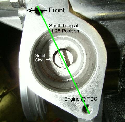
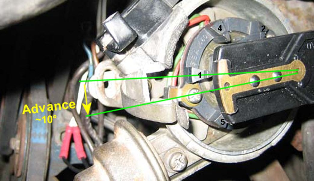
Readjust the timing: 1. JAck up front or drive up on car ramps 2. Pull plugs 3. Put in neutral 4. With 27mm socket, turn crank nose bolt so that engine is at TDC 5. Loosen sway bar end links 6. Disconnect 4 bolts holding swaybar to engine frame rails 7. remove bolt holding distributor (10mm wrench) and lift distributor 8. Note position of spindle tang in distributor mounting hole. 9. remove 4 bolts to oilpump and pull out (watch the gasket!) 10. re-align the dot (hole) in the spindle rod just above the gear with the oiling "wedge-shaped-hole" in the neck of the oil pump. 11.insert the pump a and bolt up 12. check the "11:30" alignment of the tang in the hole. ~ 30min max job.
-
Nice symmetry and orthogonal alignment of the bumper, chin piece, spook, hood and grill lines. Don\t ask me why I appreciate yours so much
-
b i n g o !!!!
-
Check fuses and fusable links