


240260280z
Free Member
-
Joined
-
Last visited
Everything posted by 240260280z
-
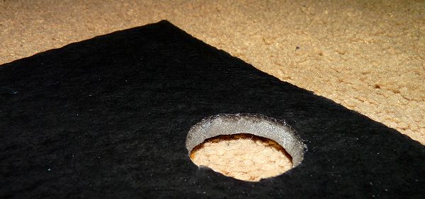
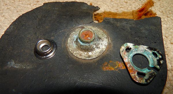
 The HD Foam seems to be the ticket. THANKS JIM! The rubber outer surface and the high density foam backing bonded very well (better than the foam board). IFor the record, I used Loctite Spray Adhesive 200. The flexibility of this combination seems to be very much like the original. I'll put a layer of foil on the back as per Jim's suggestion. Here is a detail of how well the outer rubber/fuzzy layer has bonded to the grey foam.
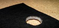

-
I will be doing in in a couple of weeks and will photo document then.
-
Thanks! I look forward to your data. Yes I mis-wrote max/min..... and in re-reading I also wrote "burning of exactly 2.4 litres of fuel" you know what I meant. I wish the edit time limit was extended to 1 month as 1 hr is not enough for my mistakes to be corrected.
-
BSFC is rate of fuel consumption divided by power made. It varies with rpm. The theory states it is supposed to be peak at maximum torque. For a 4 cycle motor, it is supposed to be ~ 0.37 to 0.45 pounds of "standardized" gasoline per hour per horse power (according to wiki). My problem is that for my HP calculation for an L24 @ 5600, I need to set Ve at 1 (complete filling and burning of exactly 2.4 litres of fuel) and a BSFC of 0.40. 0.40 seems to fit between the 0.37 to 0.45 but I have checked other peoples calculations on line and they typically use 0.50 to 0.55 for BSFC. As well if the L24 is 0.4 at 5,600rpm then it should be even better at max torque (4,400rpm).... which "feels" a little optimistic to me at this point in my model development. I am OK with the 0.40 as per the Wiki range, but I need a sanity check
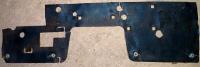
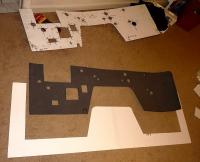
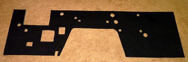
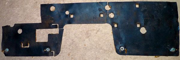
First one off the line using foam board: Replicated: Notes: 1. Fasteners to be installed next week. 2. Smaller hole sizes in more accurate locations were used to improve insulating & sound proofing. Original:

 I will do when ready. It is only 1/2 done. Should be a cool tool once finished.
Good idea! Thanks Steve!
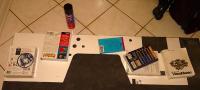
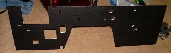
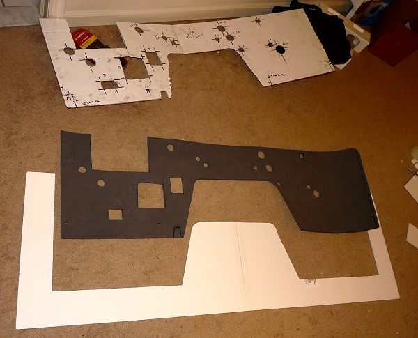
Now that I have more accurate measurements, I am making two variants of the firewall insulation panel: 1. Foam board (as per Dan's excellent recommendation above; BIG THANKS DAN!) with the jute-backed oil-proof fabric glued to the front. 2. High density foam with the jute-backed oil-proof fabric glued to the front. I think both will work well. The foam board is firmer and fits well (when I tested the template), however the high density foam seems closer in thickness compared to the original and it will soundproof and insulate better. I also sourced correct size nickle snaps that I will secure with ss hardware to replicate the floor mat snaps on the original. Here is the freshly cut foam board being glued to the fabric that is very similar to the original. There is a small square of the high density foam being test glued on the upper right to see if the glue eats it. Here is the original template and the high density foam cut out along with scraps.
I will do when ready. It is only 1/2 done. Should be a cool tool once finished.
Good idea! Thanks Steve!
Now that I have more accurate measurements, I am making two variants of the firewall insulation panel: 1. Foam board (as per Dan's excellent recommendation above; BIG THANKS DAN!) with the jute-backed oil-proof fabric glued to the front. 2. High density foam with the jute-backed oil-proof fabric glued to the front. I think both will work well. The foam board is firmer and fits well (when I tested the template), however the high density foam seems closer in thickness compared to the original and it will soundproof and insulate better. I also sourced correct size nickle snaps that I will secure with ss hardware to replicate the floor mat snaps on the original. Here is the freshly cut foam board being glued to the fabric that is very similar to the original. There is a small square of the high density foam being test glued on the upper right to see if the glue eats it. Here is the original template and the high density foam cut out along with scraps.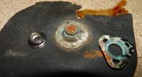
 These posts should hold most of the info you need http://forums.ctzcc.com/viewtopic.php?p=21113&sid=15533ae7e45c3abb49a047c9104209de http://www.classiczcars.com/forums/showthread.php?10246-no-tach-with-crane-ign.
I tried the "peel and seal" aluminum tape with asphalt roofing product to reduce noise in my S2000 trunk. It was easy to install and worked great at reducing noise but the tar-like smell still persists. I regret doing it however I will not peel it off as it will exposed more stinky stuff. The smell has decreased but not as fast as some have claimed and not as much as some have claimed. I will give it a year and see what happens. However, as it dampens great, I want to use it to dampen the panels on my 71 240z resto. I am thinking that I may be able to paint some substance over (like Nissan did on the floor pan asphalt) it to effectively seal the smell in. Any recommendations for a paint-able sealant? Thanks
Made a pitot tube out of aluminum tubes. It will be a probe for flow tests. Also continued fabrication of firewall interior panels.
Thanks, I am beginning to think the gasket may be for the needle valve as the carb kit had two bags, one had nearly all the parts and a small second bag had a needle valve and a fibre gasket. I am guessing that the two bags were from different mfgr's and two gaskets were provided for the needle valve... but I never saw an aluminum needle valve gasket as it will change the fuel height. I got the kits at Weber Carb Direct so I'll take your advice and ring them. The main body gaskets fit fine but I had to remove the floats before installing. There were actually a few different gaskets in the kit for different body castings/machinings.
When the car dies, does the tach drop quickly ahead of the rpms? Try upgrading to a 280zx distributor/ignition if it turns out to be your ignition box.
Looking for BSFC to improve a calculation's accuracy. Any data or estimates is most welcome. Right now I am using 0.4 at 5600 but I feel it may be too low.
OR it could be a broken spring in the needle assembly Read this great write up: http://www.classictiger.com/techtips/motach.html
This is pretty much an educated guess: I think the 100uF cap in the circuit could be kaput and the diode/cap "tank circuit" is not working. Transients (back emf) on the tach's anemeter are not dampened correctly when going from higher rpm to lower rpm during a gear change.
Datsun 1200 tach Datsun 1200 tach Datsun 240z
These posts should hold most of the info you need http://forums.ctzcc.com/viewtopic.php?p=21113&sid=15533ae7e45c3abb49a047c9104209de http://www.classiczcars.com/forums/showthread.php?10246-no-tach-with-crane-ign.
I tried the "peel and seal" aluminum tape with asphalt roofing product to reduce noise in my S2000 trunk. It was easy to install and worked great at reducing noise but the tar-like smell still persists. I regret doing it however I will not peel it off as it will exposed more stinky stuff. The smell has decreased but not as fast as some have claimed and not as much as some have claimed. I will give it a year and see what happens. However, as it dampens great, I want to use it to dampen the panels on my 71 240z resto. I am thinking that I may be able to paint some substance over (like Nissan did on the floor pan asphalt) it to effectively seal the smell in. Any recommendations for a paint-able sealant? Thanks
Made a pitot tube out of aluminum tubes. It will be a probe for flow tests. Also continued fabrication of firewall interior panels.
Thanks, I am beginning to think the gasket may be for the needle valve as the carb kit had two bags, one had nearly all the parts and a small second bag had a needle valve and a fibre gasket. I am guessing that the two bags were from different mfgr's and two gaskets were provided for the needle valve... but I never saw an aluminum needle valve gasket as it will change the fuel height. I got the kits at Weber Carb Direct so I'll take your advice and ring them. The main body gaskets fit fine but I had to remove the floats before installing. There were actually a few different gaskets in the kit for different body castings/machinings.
When the car dies, does the tach drop quickly ahead of the rpms? Try upgrading to a 280zx distributor/ignition if it turns out to be your ignition box.
Looking for BSFC to improve a calculation's accuracy. Any data or estimates is most welcome. Right now I am using 0.4 at 5600 but I feel it may be too low.
OR it could be a broken spring in the needle assembly Read this great write up: http://www.classictiger.com/techtips/motach.html
This is pretty much an educated guess: I think the 100uF cap in the circuit could be kaput and the diode/cap "tank circuit" is not working. Transients (back emf) on the tach's anemeter are not dampened correctly when going from higher rpm to lower rpm during a gear change.
Datsun 1200 tach Datsun 1200 tach Datsun 240z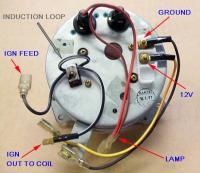
 From Opel GT Forum. Seems similar to Z: Tach Circuit The tach uses a relatively simple analog circuit with two transistors. - The first transistor detects the pulse from the points being opened. The pulse from the points is actually an oscillation that lasts a couple of milliseconds. It starts out with an AC component of about +/- 50V that damps down to a DC voltage (about 24V) in a couple of milliseconds (ms). Once the spark is done the voltage drops to about 12V DC and stays there until the points close again. - This is not an easy signal to deal with, so the first transistor is used to convert it to a simple square wave pulse with about a 2ms duration. The output of this stage is then a set of pulses of 2ms duration on and the rest off, with one pulse for each time the points open. - The second transistor acts as a current amplifier so this pulse train can be used to drive the meter. The higher the duty cycle of the pulses, the more the needle moves. - The meter will go to full scale with about 10ma of current. - Interestingly, the tach actually works on 6V internally. Part of the circuit drops the 12V input to 6V to operate the tach.
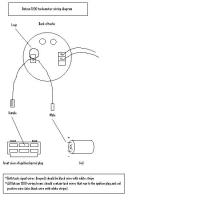
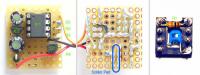
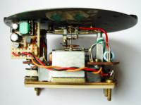
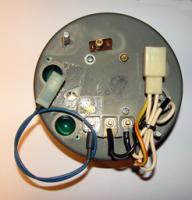
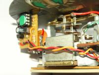
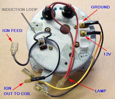
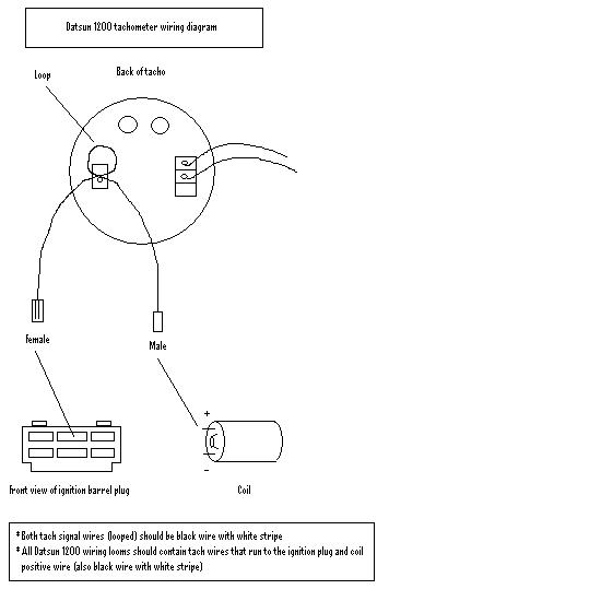
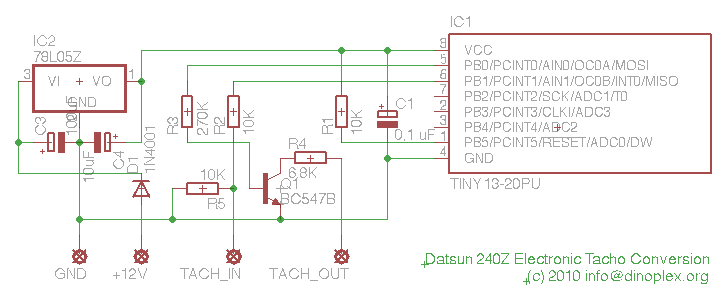
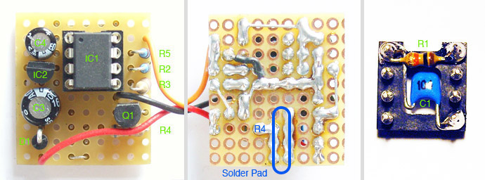
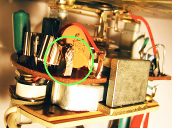
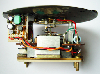
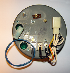
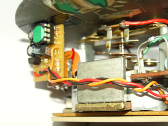
Web search found this: Source Reference : http://www.dinoplex.org/tachoconversion/index.html Current driven tachos are wired in line with the primary coil wiring, such tachos can be easily identified by the cable loop at the back of the tacho. Smith tachos of this type are labeled "RVI". The tacho is not actually wired to any of the ignition components, the wire connected to the coil (+) terminal just induces a magnetic field for each ignition impulse via a small wire loop on the back of the tacho, which is then picked up by a small coil within the tacho. This type of tacho was installed until the late sixties to early seventies, when the automotive industry moved to ignition kickback driven tachos. Kickback controlled tachos have a single wire connected to the negative primary terminal on the coil, and use the inductive kickback of each ignition, which creates a short impulse with several hundred volts at the primary terminals to display the engines RPM. Smith tachos of this type are labeled "RVC". In the early eighties, voltage controlled tachos, also called "electronic tachos", were installed when the industry switched to electronic controlled ignition systems. A voltage controlled tacho receives a 12 volt square wave signal to display the engines RPM. Nowadays, most if not all aftermarket and oem tachos units are voltage controlled tachos. The tacho types listed above are not interchangeable. Connecting a modern voltage controlled tacho directly to the coil in an older kickback setup might damage the tacho. Also, connecting a kickback controlled tacho to a modern capacitive ignition system can also damage the tacho due to the higher primary voltage. For many setups tacho adapters are available from a range of companies. As example connecting an electronic tacho to a kickback setup can be easily handled by a standard tacho adapter. There is also a another tacho adapter type available to connect older kickback tachos to newer electronic ignitions by means of a tiny transformer to create the kickback impulse. As current driven tachos are difficult to integrate with an external adapter, the scope of this document is to offer an easy way to do a conversion instead. How does the conversion work The Datsun 240Z current driven tacho is based on a two transistor circuit, which amplifies the induction impulse from the coil wire loop. The conversion circuit listens to a 12 volt square wave input from a modern electronic ignition and then creates a 500mV 1ms induction impulse signal similar to the original one, which is then directly fed to the current driven tachos input stage. This is realized by a relatively simple circuit with just one transistor and a voltage regulator, the signal processing is handled by an AVR ATtiny13A microcontroller. You need an AVR compatible programmer such as the low cost AVRISP mkII, or someone with a programmer to flash the microcontroller with the firmware. The firmware is provided for downloading below. Cost for all parts is 6-8€, The installation is simple as the circuit is soldered directly to one input pin of the tachos pickup coil like a daughterboard. The tacho itself is not modified, so the conversion is easily reversed if required. Building and installing the conversion circuit Here is a shopping list of the required parts: 1 AVR ATtiny13A Microcontroller DIP 8 IC1 3 10K Ohm Resistor 0204/5 R1, R2, R5 1 270K Ohm Resistor 0204/5 R3 1 6.8K Ohm Resistor 0204/5 R4 1 0,1uF Capacitor C1 1 10uF Electrolytic Capacitor C4 1 100 uF Electrolytic Capacitor C3 1 1N4001 Diode D1 1 MC78L05A Voltage Regulator TO-92 IC2 1 BC547B Transistor TO-92 Q1 1. Flash the ATtiny13A microcontroller with the firmware (download). Solder all components to a small prototyping board. A board with 9 x 10 holes fits nicely. Solder R1 and C1 below the DIP socket to save some space (see image below on the right side). The output wire of R4 (below the red wire in the picture) ends up in a solder pad for installing the board later on, see blue area in the middle picture below. Here are the Eagle files with the schematic and the PCB layout as a download: 240Z Tacho Conversion.zip 2. Remove the 240Z tacho from the dashboard by unscrewing the two winged nuts on the back and pulling the tacho forward. Make sure its the correct type with the white wire in a loop on the back. Remove the screws holding the black plastic bezel, then remove the electric terminals, the white coil loop and the two screws on the back to get to the PCB. 3. Install a third terminal using a screw and nut in the unused hole for the 6V terminal (see picture below on the left). Solder GND (black wire) to the ground post in the middle, +12V (red wire) to the +12V post on the left and TACH_IN (orange wire) to the new contact on the right side. 4. Identify the small coil below the current loop terminal (the coil is on the right picture below in the lower left corner). The black wire of the coil connects to a terminal on the tachos PCB, on the right picture below marked with a green circle. 5. Solder the conversion boards TACH_OUT solder pad (blue marking in the PCB picture above) to the terminal with the black wire coming from the coil (green circle on the picture above right). Take care that the board does not touch the right terminal/red wire. 6. You are now ready to test the tacho conversion. The firmware will move the tach needle to ~800 RPM for 100 ms after the tacho is powered on, so if you apply power to the +12V and GND external terminal, you should be able see the needle moving if the converter has been installed correclty. Should the tacho not work, make sure that you have installed and wired all components as documented, and that the ATtiny13A chip is flashed correctly. With a scope you should be able to measure the incoming tacho square wave signal on pin 6 of the ATtiny13 chip and the output PWM wave signal on pin 5 (on power up you should see a negative square wave for 100 ms). 7. If you have a frequency generator capable of supplying a low frequency square wave signal, connect the ground output of the generator to the external GND terminal, and the signal output to the TACH_IN third terminal. With the frequency generator set to 50 Hz, the tacho should now display 1000 RPM (for a 6 cylinder engine it's 100 Hz=2000 RPM, 150 Hz=3000 RPM, 200 Hz=4000 RPM etc.) If the needle moves but indicates a slightly different RPM value, adjust the tacho by turning the calibration potentiometer, which can be accessed through a hole between the two direction light sockets (Warning: use a plastic screwdriver or put tape on the screwdriver shaft so you won't create an electrical contact between the trim pot and the outer enclosure! This could kill the tach transistor which is located next to the terminal marked with a green circle. If this should happen to you, use a BC547C as replacement). My '72 tacho turned out to be quite precise after calibration, with a maximum RPM display error of less than 3% at 4000 and 6000 RPM. 8. You are now ready for the reinstallation of the tacho. Create a short wire for the TACH_IN output for easier connection after the tacho has been reinstalled (see image with blue wire below), then reinstall the tacho and connect TACH_IN to your electronic ignition. 240Z Tacho Conversion.zip 240z_itacho2square_v3.hex.zip
From Opel GT Forum. Seems similar to Z: Tach Circuit The tach uses a relatively simple analog circuit with two transistors. - The first transistor detects the pulse from the points being opened. The pulse from the points is actually an oscillation that lasts a couple of milliseconds. It starts out with an AC component of about +/- 50V that damps down to a DC voltage (about 24V) in a couple of milliseconds (ms). Once the spark is done the voltage drops to about 12V DC and stays there until the points close again. - This is not an easy signal to deal with, so the first transistor is used to convert it to a simple square wave pulse with about a 2ms duration. The output of this stage is then a set of pulses of 2ms duration on and the rest off, with one pulse for each time the points open. - The second transistor acts as a current amplifier so this pulse train can be used to drive the meter. The higher the duty cycle of the pulses, the more the needle moves. - The meter will go to full scale with about 10ma of current. - Interestingly, the tach actually works on 6V internally. Part of the circuit drops the 12V input to 6V to operate the tach.
Web search found this: Source Reference : http://www.dinoplex.org/tachoconversion/index.html Current driven tachos are wired in line with the primary coil wiring, such tachos can be easily identified by the cable loop at the back of the tacho. Smith tachos of this type are labeled "RVI". The tacho is not actually wired to any of the ignition components, the wire connected to the coil (+) terminal just induces a magnetic field for each ignition impulse via a small wire loop on the back of the tacho, which is then picked up by a small coil within the tacho. This type of tacho was installed until the late sixties to early seventies, when the automotive industry moved to ignition kickback driven tachos. Kickback controlled tachos have a single wire connected to the negative primary terminal on the coil, and use the inductive kickback of each ignition, which creates a short impulse with several hundred volts at the primary terminals to display the engines RPM. Smith tachos of this type are labeled "RVC". In the early eighties, voltage controlled tachos, also called "electronic tachos", were installed when the industry switched to electronic controlled ignition systems. A voltage controlled tacho receives a 12 volt square wave signal to display the engines RPM. Nowadays, most if not all aftermarket and oem tachos units are voltage controlled tachos. The tacho types listed above are not interchangeable. Connecting a modern voltage controlled tacho directly to the coil in an older kickback setup might damage the tacho. Also, connecting a kickback controlled tacho to a modern capacitive ignition system can also damage the tacho due to the higher primary voltage. For many setups tacho adapters are available from a range of companies. As example connecting an electronic tacho to a kickback setup can be easily handled by a standard tacho adapter. There is also a another tacho adapter type available to connect older kickback tachos to newer electronic ignitions by means of a tiny transformer to create the kickback impulse. As current driven tachos are difficult to integrate with an external adapter, the scope of this document is to offer an easy way to do a conversion instead. How does the conversion work The Datsun 240Z current driven tacho is based on a two transistor circuit, which amplifies the induction impulse from the coil wire loop. The conversion circuit listens to a 12 volt square wave input from a modern electronic ignition and then creates a 500mV 1ms induction impulse signal similar to the original one, which is then directly fed to the current driven tachos input stage. This is realized by a relatively simple circuit with just one transistor and a voltage regulator, the signal processing is handled by an AVR ATtiny13A microcontroller. You need an AVR compatible programmer such as the low cost AVRISP mkII, or someone with a programmer to flash the microcontroller with the firmware. The firmware is provided for downloading below. Cost for all parts is 6-8€, The installation is simple as the circuit is soldered directly to one input pin of the tachos pickup coil like a daughterboard. The tacho itself is not modified, so the conversion is easily reversed if required. Building and installing the conversion circuit Here is a shopping list of the required parts: 1 AVR ATtiny13A Microcontroller DIP 8 IC1 3 10K Ohm Resistor 0204/5 R1, R2, R5 1 270K Ohm Resistor 0204/5 R3 1 6.8K Ohm Resistor 0204/5 R4 1 0,1uF Capacitor C1 1 10uF Electrolytic Capacitor C4 1 100 uF Electrolytic Capacitor C3 1 1N4001 Diode D1 1 MC78L05A Voltage Regulator TO-92 IC2 1 BC547B Transistor TO-92 Q1 1. Flash the ATtiny13A microcontroller with the firmware (download). Solder all components to a small prototyping board. A board with 9 x 10 holes fits nicely. Solder R1 and C1 below the DIP socket to save some space (see image below on the right side). The output wire of R4 (below the red wire in the picture) ends up in a solder pad for installing the board later on, see blue area in the middle picture below. Here are the Eagle files with the schematic and the PCB layout as a download: 240Z Tacho Conversion.zip 2. Remove the 240Z tacho from the dashboard by unscrewing the two winged nuts on the back and pulling the tacho forward. Make sure its the correct type with the white wire in a loop on the back. Remove the screws holding the black plastic bezel, then remove the electric terminals, the white coil loop and the two screws on the back to get to the PCB. 3. Install a third terminal using a screw and nut in the unused hole for the 6V terminal (see picture below on the left). Solder GND (black wire) to the ground post in the middle, +12V (red wire) to the +12V post on the left and TACH_IN (orange wire) to the new contact on the right side. 4. Identify the small coil below the current loop terminal (the coil is on the right picture below in the lower left corner). The black wire of the coil connects to a terminal on the tachos PCB, on the right picture below marked with a green circle. 5. Solder the conversion boards TACH_OUT solder pad (blue marking in the PCB picture above) to the terminal with the black wire coming from the coil (green circle on the picture above right). Take care that the board does not touch the right terminal/red wire. 6. You are now ready to test the tacho conversion. The firmware will move the tach needle to ~800 RPM for 100 ms after the tacho is powered on, so if you apply power to the +12V and GND external terminal, you should be able see the needle moving if the converter has been installed correclty. Should the tacho not work, make sure that you have installed and wired all components as documented, and that the ATtiny13A chip is flashed correctly. With a scope you should be able to measure the incoming tacho square wave signal on pin 6 of the ATtiny13 chip and the output PWM wave signal on pin 5 (on power up you should see a negative square wave for 100 ms). 7. If you have a frequency generator capable of supplying a low frequency square wave signal, connect the ground output of the generator to the external GND terminal, and the signal output to the TACH_IN third terminal. With the frequency generator set to 50 Hz, the tacho should now display 1000 RPM (for a 6 cylinder engine it's 100 Hz=2000 RPM, 150 Hz=3000 RPM, 200 Hz=4000 RPM etc.) If the needle moves but indicates a slightly different RPM value, adjust the tacho by turning the calibration potentiometer, which can be accessed through a hole between the two direction light sockets (Warning: use a plastic screwdriver or put tape on the screwdriver shaft so you won't create an electrical contact between the trim pot and the outer enclosure! This could kill the tach transistor which is located next to the terminal marked with a green circle. If this should happen to you, use a BC547C as replacement). My '72 tacho turned out to be quite precise after calibration, with a maximum RPM display error of less than 3% at 4000 and 6000 RPM. 8. You are now ready for the reinstallation of the tacho. Create a short wire for the TACH_IN output for easier connection after the tacho has been reinstalled (see image with blue wire below), then reinstall the tacho and connect TACH_IN to your electronic ignition. 240Z Tacho Conversion.zip 240z_itacho2square_v3.hex.zip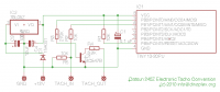

 72 was a good year for Z's! Nice car.
Yes, I just used a plastic paint from Walmart that worked fine. It was labeled Fusion. I painted all of the panels. It was a fun job and easy to do outside on a sunny day with low humidity. Just wash them first with Ajax/Comet detergent to get rid of oils and dirt, rinse well, then wipe quickly with lacquer thinner on a dust free rag prior to painting.
I think Enrique may be on to something: I'll try to take a peek inside a tach and check out the circuitry. There has to be some kind of pulse to current converter integration circuitry that drives the tach needle.
Note: This is a Microsoft Excel (XLS) Tool Click on this link or the screen shot below to download the file: Hitachi Jet Depth Calculator
Maybe do a limited edition carb set this year with cool covering or engraving or plaque on the domes or balance tube! Tres Faberge
72 was a good year for Z's! Nice car.
Yes, I just used a plastic paint from Walmart that worked fine. It was labeled Fusion. I painted all of the panels. It was a fun job and easy to do outside on a sunny day with low humidity. Just wash them first with Ajax/Comet detergent to get rid of oils and dirt, rinse well, then wipe quickly with lacquer thinner on a dust free rag prior to painting.
I think Enrique may be on to something: I'll try to take a peek inside a tach and check out the circuitry. There has to be some kind of pulse to current converter integration circuitry that drives the tach needle.
Note: This is a Microsoft Excel (XLS) Tool Click on this link or the screen shot below to download the file: Hitachi Jet Depth Calculator
Maybe do a limited edition carb set this year with cool covering or engraving or plaque on the domes or balance tube! Tres Faberge


Important Information
By using this site, you agree to our Privacy Policy and Guidelines. We have placed cookies on your device to help make this website better. You can adjust your cookie settings, otherwise we'll assume you're okay to continue.