240260280z
Free Member
-
Joined
-
Last visited
Everything posted by 240260280z
-
 I also had a 6/70 SN HLS30- 05121. RoostMonkey (Brad) found it for me in NH. Here is the link to photos: http://hammondsplains.com/zcars4sale/240z/blue240zNH/index.htm
 -
I concur with Anne G. Kay
-
From the above it is clear there are pros and cons to both sides. It also seems to depend mostly on the ability of a pump to have an internal short cycle bypass path, if it sits in the tank, and the pressures and flow rates for the application. My opinion (old school) for adding an electric pump to a carbed 240z is with Z train, the pump should have flow when on and not be dead-headed so as to minimize strain and to promote removal of internal heat. My opinion is weighted more for longevity of the pump rather than any other priority (safety risks, looks, convenience, etc.).
-
Looks like couscous, porridge or mashed potatoes...what does it taste like?
-
OK so it is not temp sensor or wiring. 1.5 and 1.75 kohm are fine. There are other items in the efi system but only two typically cause so much excess fuel. If return line to tank is blocked or your FPR is blocked/malfunctioning then fuel pressure could be too high. Another possibility is that your ECU is malfunctioning and holding the injectors open too long or your injectors are oversized. Here is a graph showing sensors and ECU logic that contribute to the amount of fuel used:
-
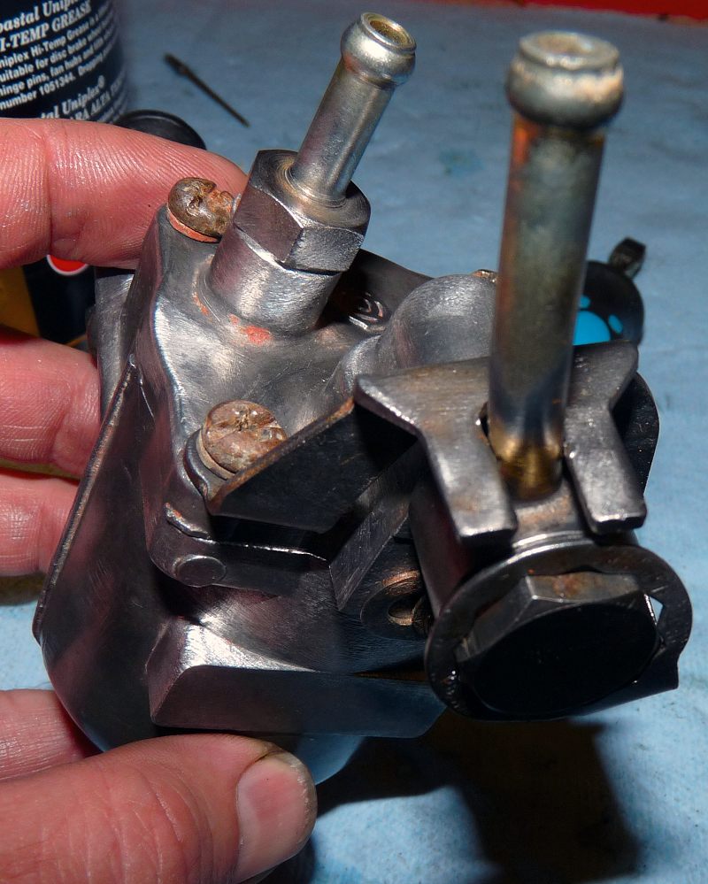
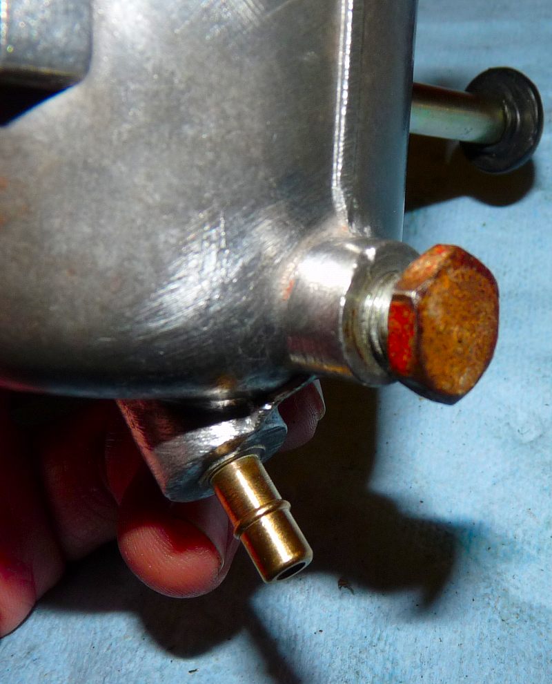
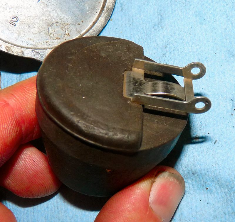
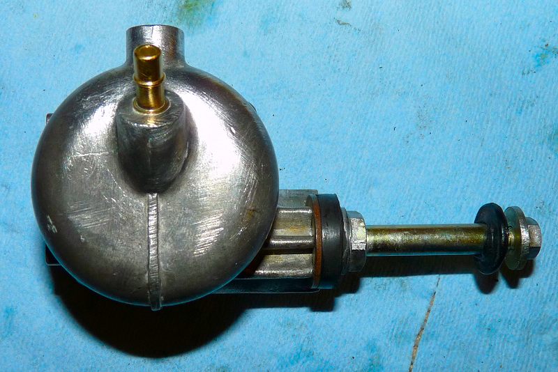
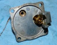
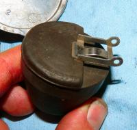
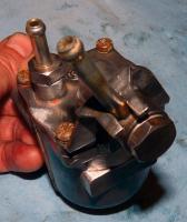
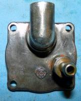
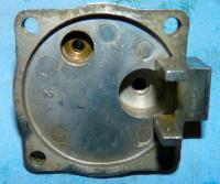
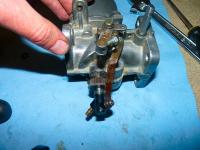
Fuel bolt captive retainer in place Fuel bowl drain installed. Fuel bowl attached to carb body. Note the rubber shock mounts. That's all folks!


-
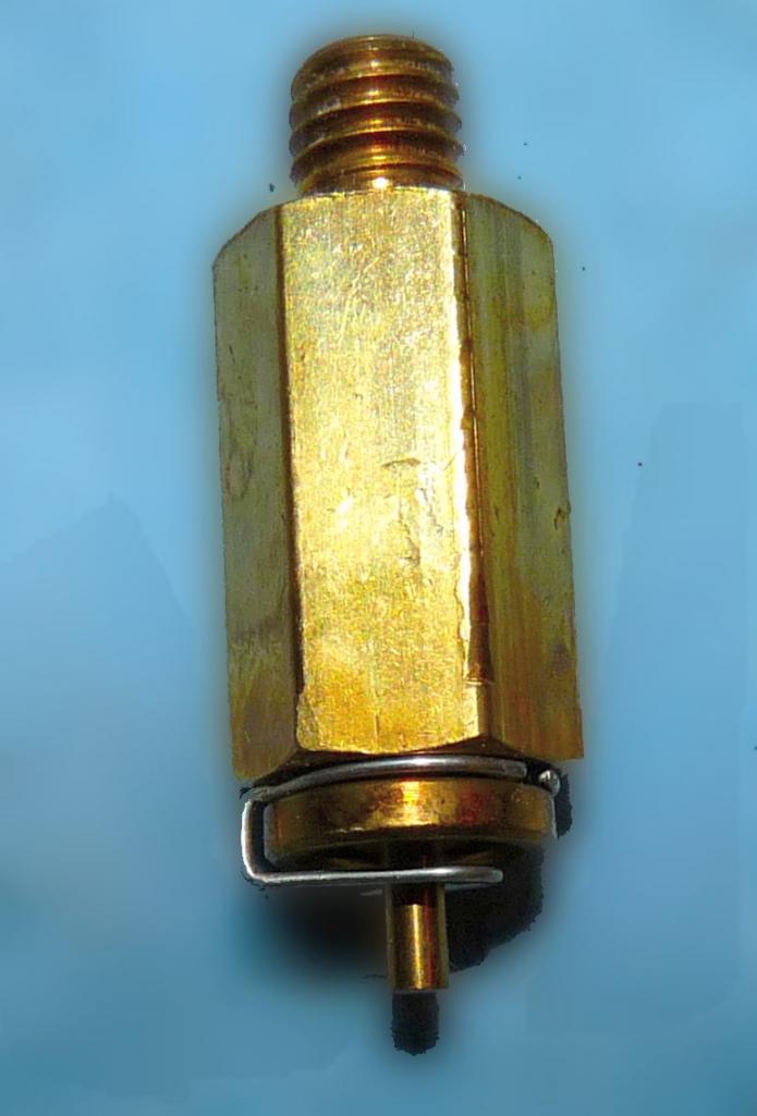
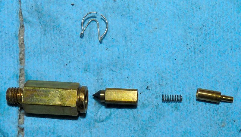
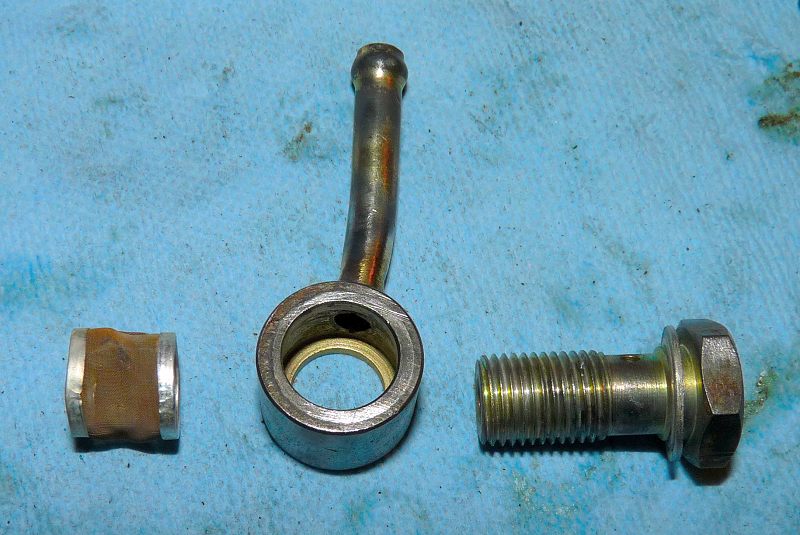
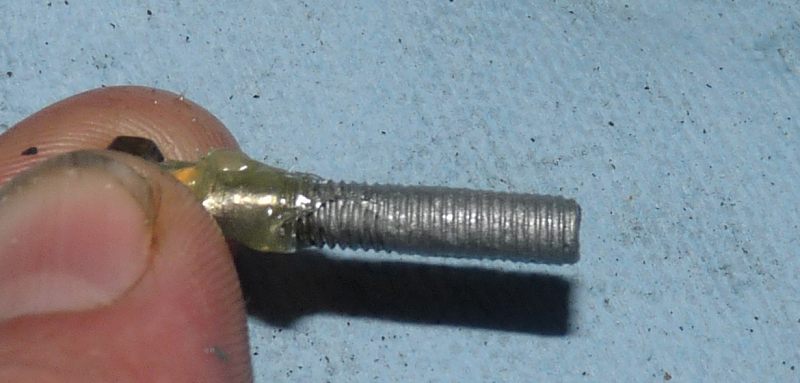
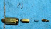
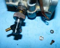
Fuel Bowl Needle Valve Found all the parts (Everything will workout if you let it) Note the black rubber nose on the needle. Installed The float. Note: the tab in the middle is adjustable by bending. To install the float, a free floating pin is used. Closeup of how the float presses against the needle valve Fuel filter and banjo joint Detail Locking fastener. Same


-
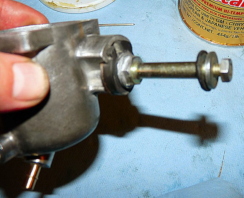
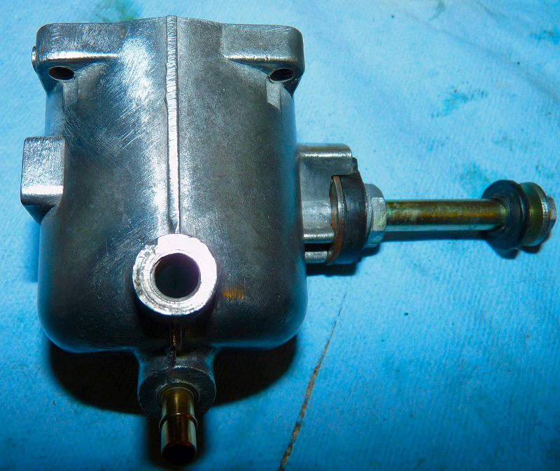
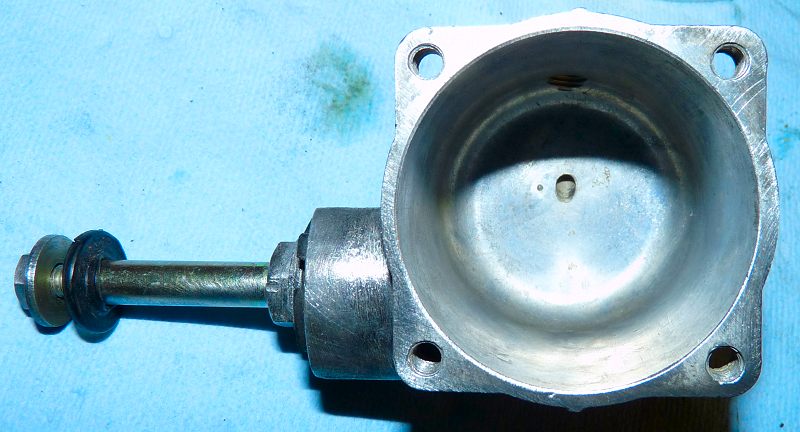
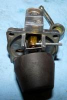
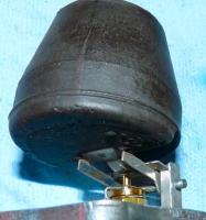
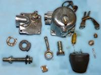
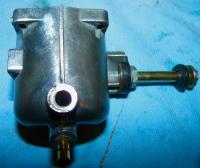
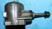
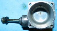
The Parts Install shock mount washer Install rubber shock mount Install mounting shaft Some images of the fuel bowl Hitachi Logo


-
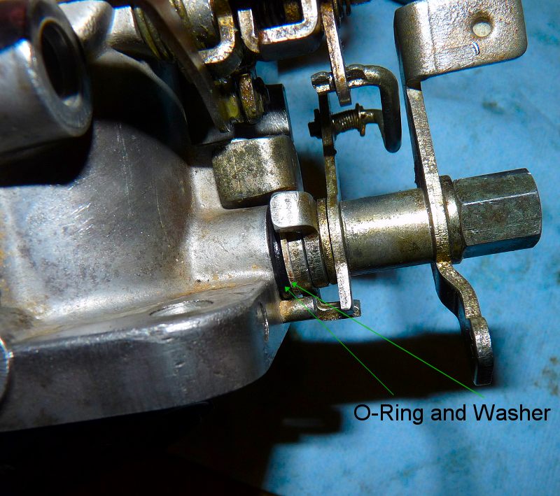
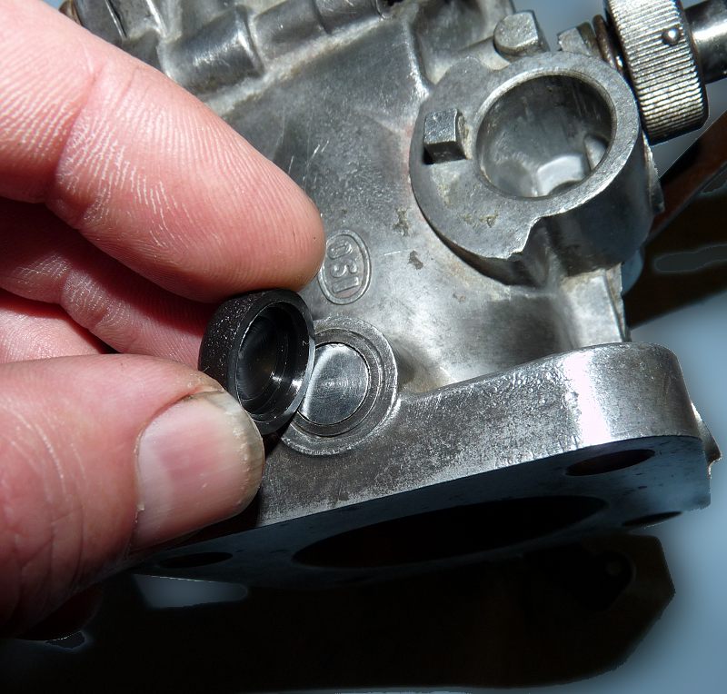
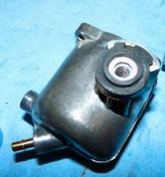
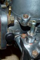
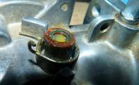
Excellent point! Presently the side force on the shaft is minimal as the O-ring is very low in height. As well, I am guessing that a leak would suck the washer in closer, especially at idle. I could put a thinner washer there to completely unload the butterfly valve but I did not have one here in NJ. Maybe I should just drill out another plastic screw cap, sand it to the correct height then glue it on... yes I think that would be even better! At $0.20 each it is not a risky venture. Thanks for your insight! Another set of eyes and brain is great!
-
Nah, I defined thrifty canuck eh? Lets hope the engine heat does not loosen the glue or it will be RTV time.
-
The microfiche shows a part number 12033-P7910 replaces 12033-P7900 replaces 12033-P8370 Reference: http://carfiche.com/fiche009/s130/2/c07.gif
-
I am fortunate and have everything out of the car. I just need to make a new one. I tried to order one from VB/BD yesterday but no availability.
-
What is the actual hole diameter(in mm) for the pin-clips?
-
Synthetic is ok. Just make sure it is NOT GL-5 gear formula with sulfur.
-
Thanks a million Phred! I appreciate your intervention
-
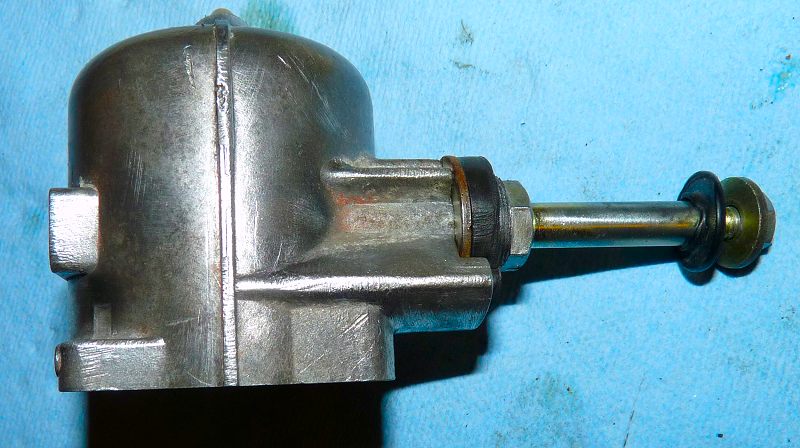
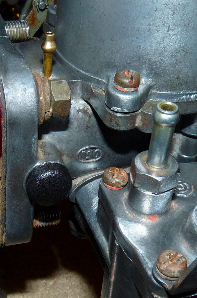
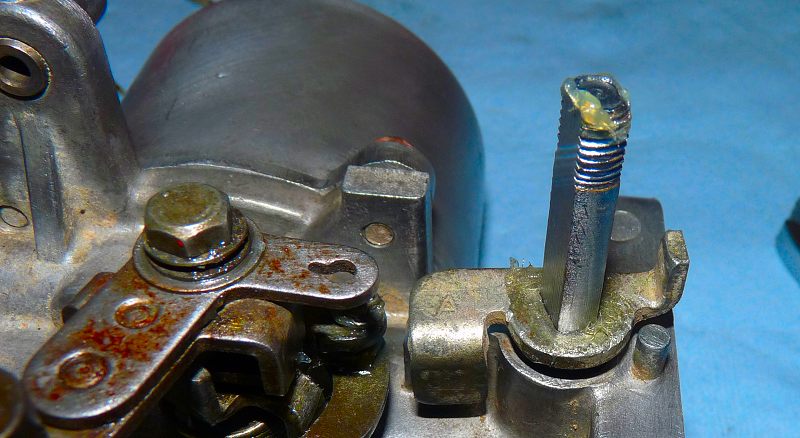
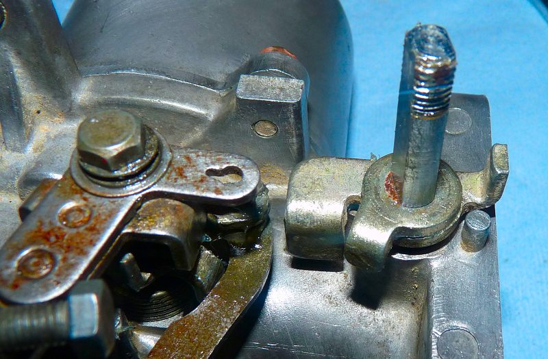
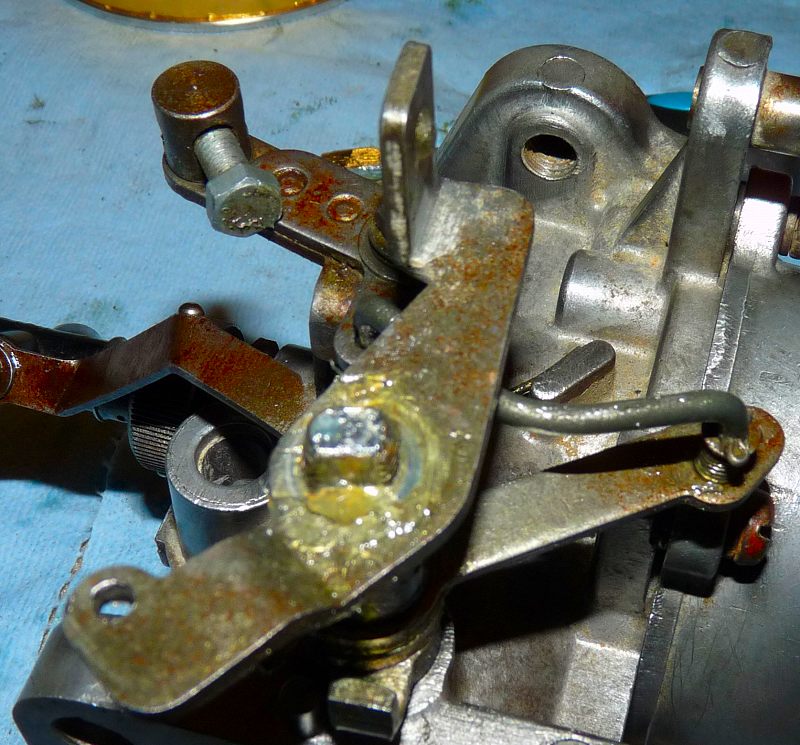
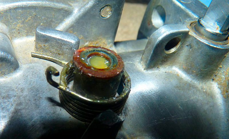
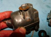
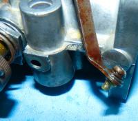
A plastic cap (screw cover) from ACE hardware's parts bin and sealant/goo/glue seal the outside bushing nicely. Installed A thin washer and an o-ring seal the inside bushing with negligible effect on the throttle return.


-
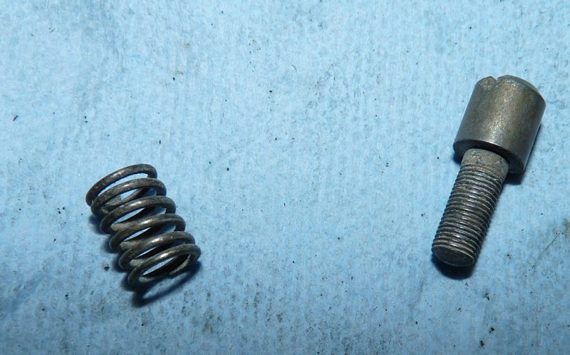
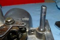
The limit of 10 pictures per post bumped this one: Exploded drawing of throttle assembly Idle set screw and spring. Note the fine thread. Installed.


-
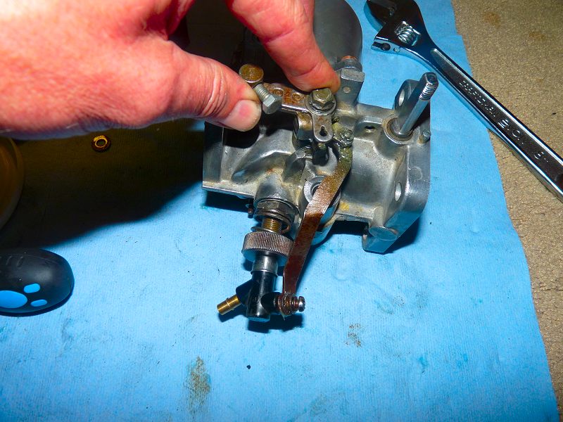
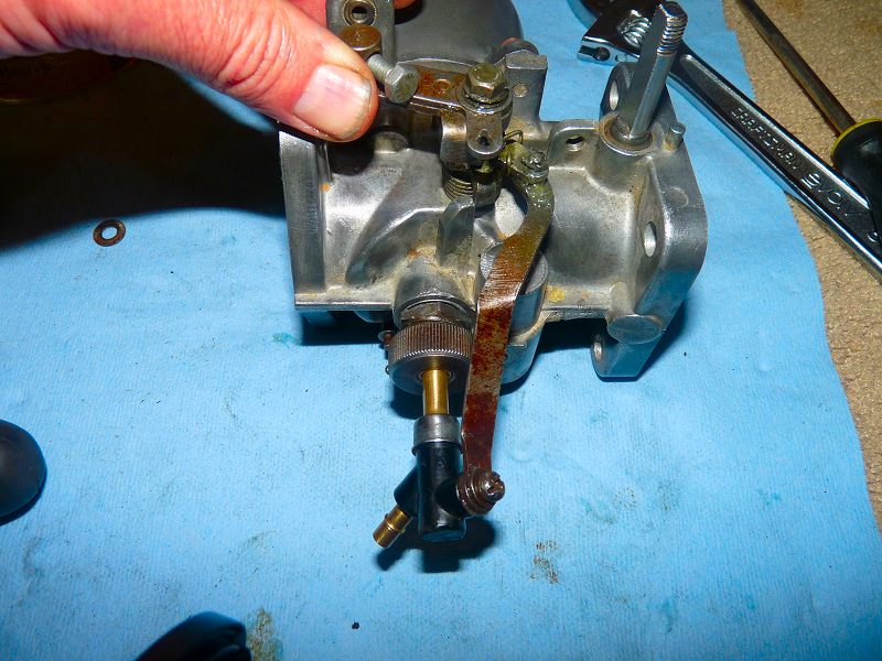
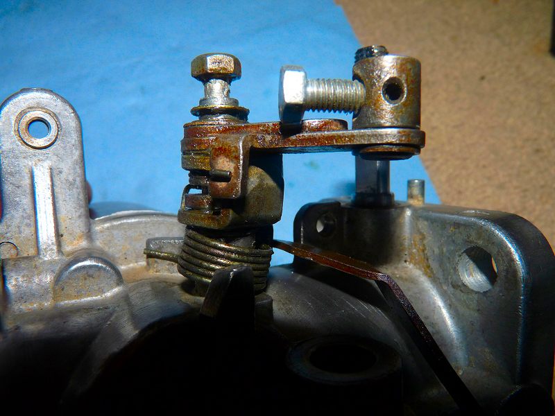
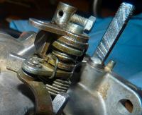
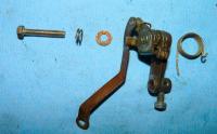
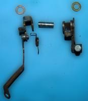
Throttle Assembly parts in their relative positions. Throttle shaft. The first part is installed. This is the idle lever. A set screw pushes it down to open the throttle and increase idle speed. Next is another plate. This is just the WOT stopping plate. A washer is installed. Grease it well on both sides. Next is another plate with a connecting rod to the choke assembly. You have to twist and bend a little to fit this one. The first step to fitting is to insert the rod into the choke assemble. The way this works is very simple: As the choke is applied, it pulls the rod. In turn, the rod turns the throttle assembly which opens the throttle a little and increases engine rpms when the choke is on. Another sleeve is installed. Note that it fits in the plate above. Use lots of grease on the ends and inside. This is the plate that is pushed by your foot via the throttle linkage. A lock washer holds it all together A final deep bolt with recess is installed.


-
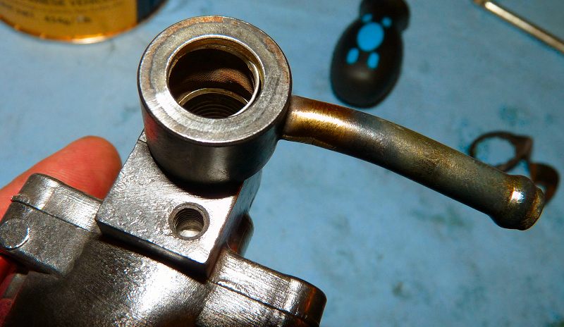
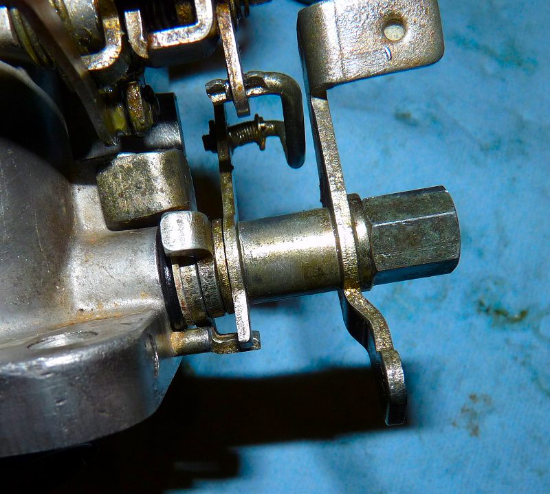
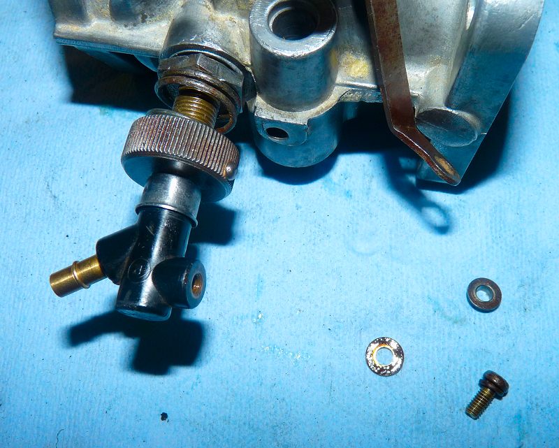
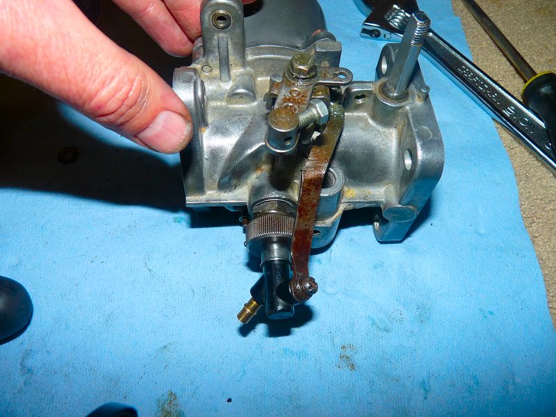
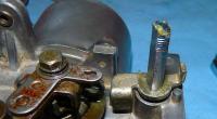
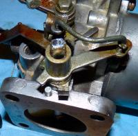
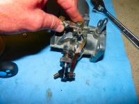
Insert the nozzle and prepare the hardware. Install the sleeve. Insert the screw and lock washer. Insert the flat washer on the other side. Use lots of grease. Move the choke lever and rotate the nozzle to position the long plate so that the screw aligns with the threaded hole in the nozzle. Snug the screw in place. Test the choke functioning by lifting the lever. The nozzle should drop and no binding should occur. Release the choke lever and the nozzle should snap up into place without binding.


-
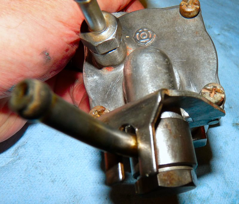
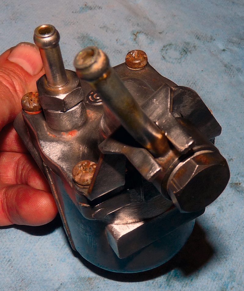
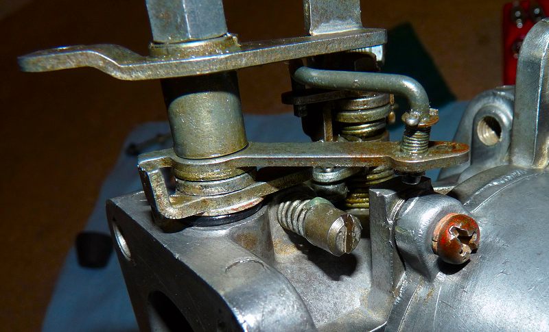
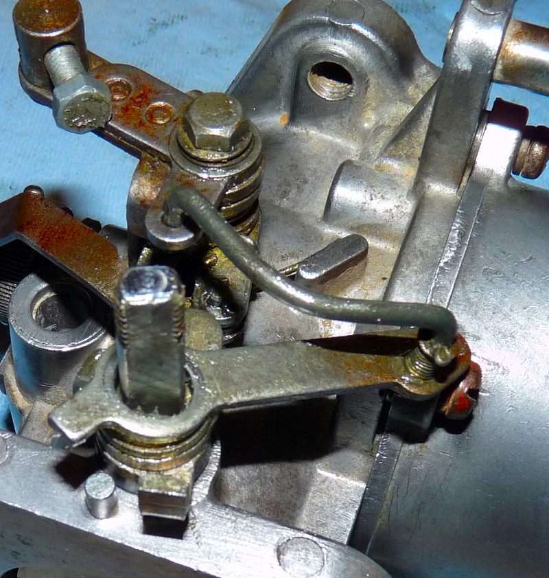
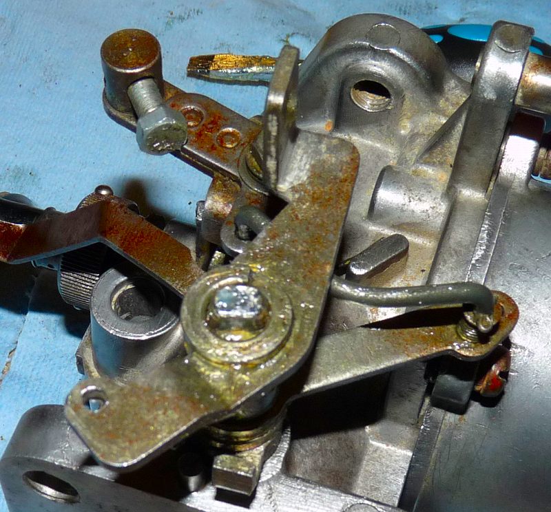
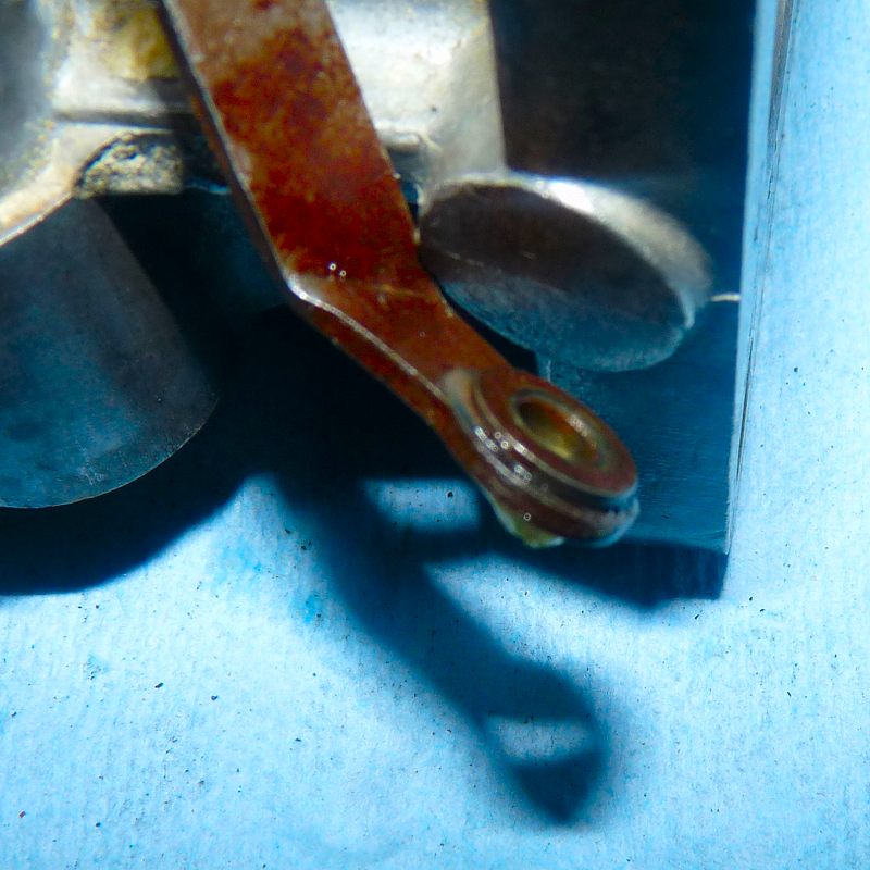
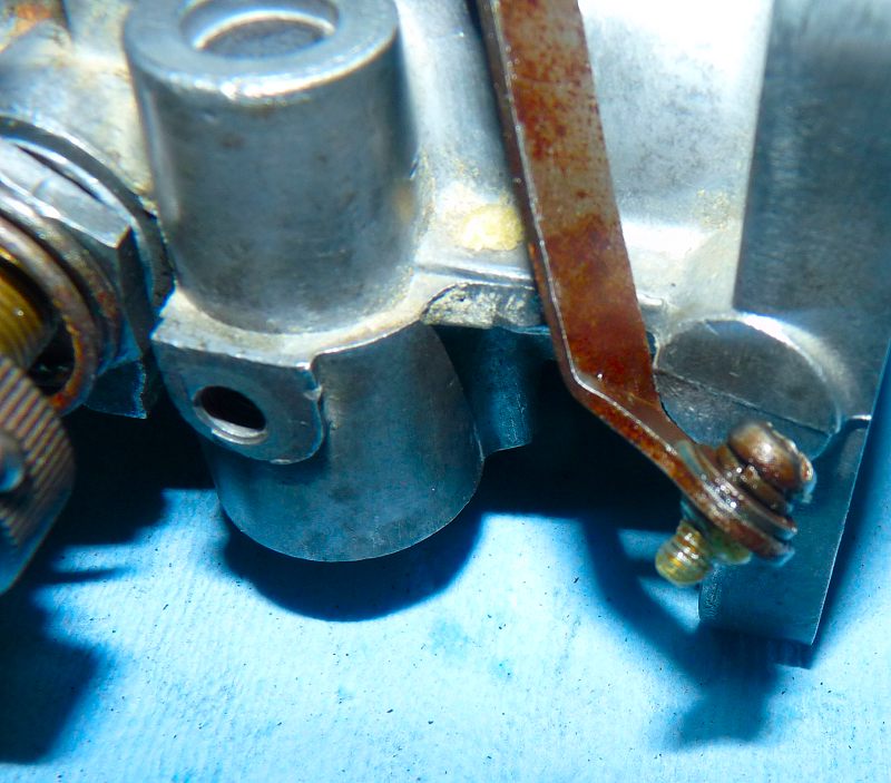
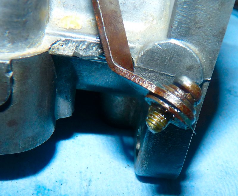
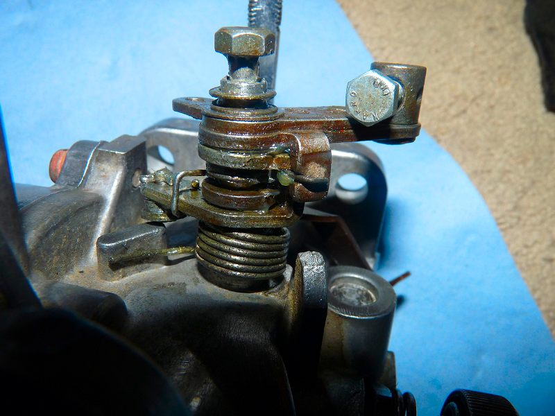
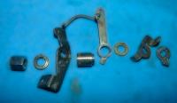
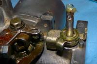
This is the most complex assembly. I started to photocopy a step-by-step but I messed up so I got tired and reassembled and took fewer ones. Here are the key parts loosely in their relative positions. The long plate on the left lowers and raises the jet nozzle. The plate on the right is connected to the choke cable. The assembly is also connects via a small rod to the throttle assemble (as the jet is lowered i.e. choke applied, the small rod opens the throttle a little to give a faster idle. Lots of grease helps this assembly work well. Here are the remaining parts with the items in the above photo assembled. A spring and washer are installed on the body. The rest of the assembly mounts on top and looks like this: The bolt that holds it together needs antiseize and grease. Here is another angle with interconnection details: And another:


-
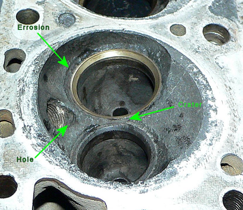
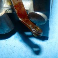
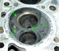
This is #6 in the E31 I am restoring. Looks like water but maybe detonation? Sure it can be ground and welded up then machined back to shape like a racing head plus new seats but I went for a Maxima N47 with custom cam from BMC in Arizona.... and probably saved $. Unfortunately, I am now reassembling and noted the corresponding piston top from #6 is peppered with small holes and it is 5grams less that the others. I may need that tended to with a welder and surface grind.
-
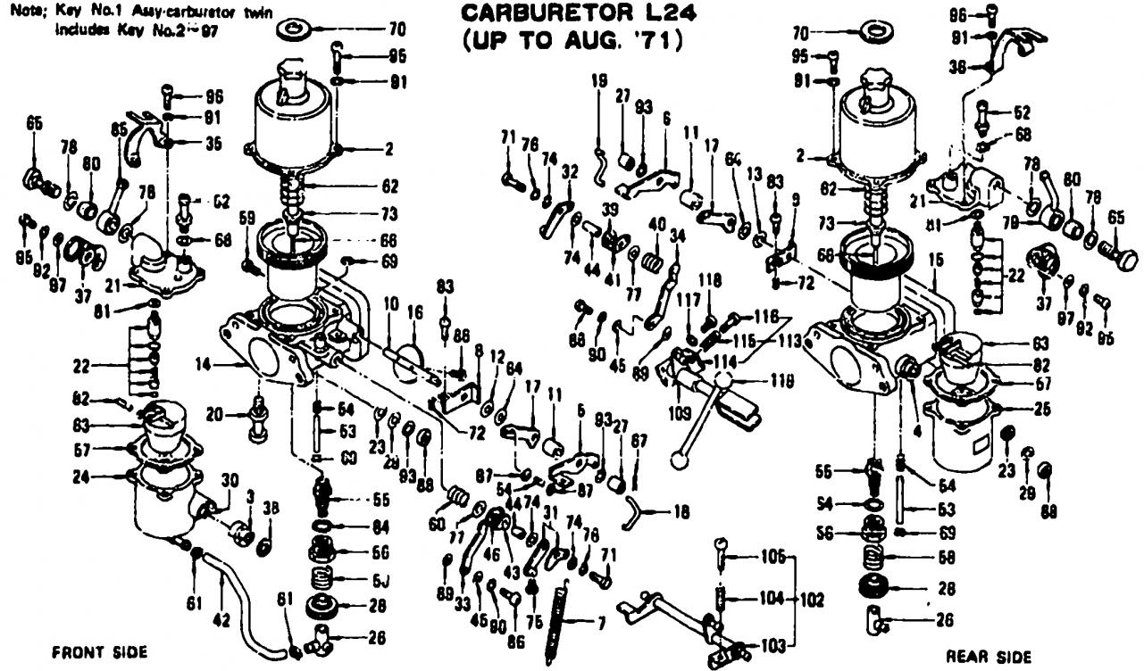
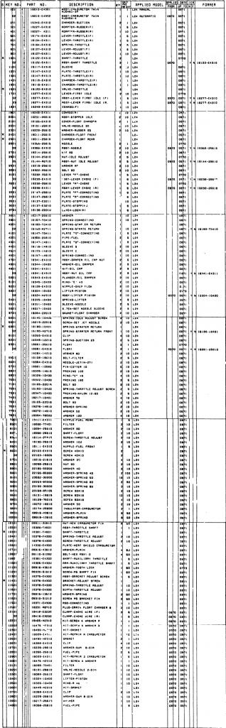
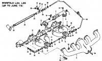
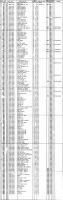
Note: I compressed all files into a .zip archive (winzip.com). This way you can get the big parts list in its full glory and clarity. I had to do this as, unfortunately, this website limits image size and compresses images so the parts list picture below is not very useful. 240Z SU Exploded View and Parts List.zip

-
Oops! I even looked at that too. Duh I am sorry :stupid:
-
Yikes.... it is those darn exhaust liners that are the cause. They expand and contract at a different rate from the aluminum that surrounds them. They probably conduct heat faster as they are thin and less of a heat sink than the surrounding aluminum. Time to get a new head. You can use that one for porting experiments. A Maxima N47 would work nicely but you have those pesky liners again. Mine cracked in exactly the same spot: btw this follows my question last week as to why Nissan placed the two exhaust runners for 3 and 4 side-by-side in the head? So much heat in one area is unwise.
-
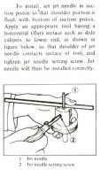
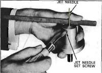
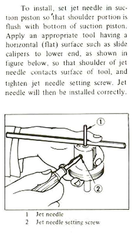
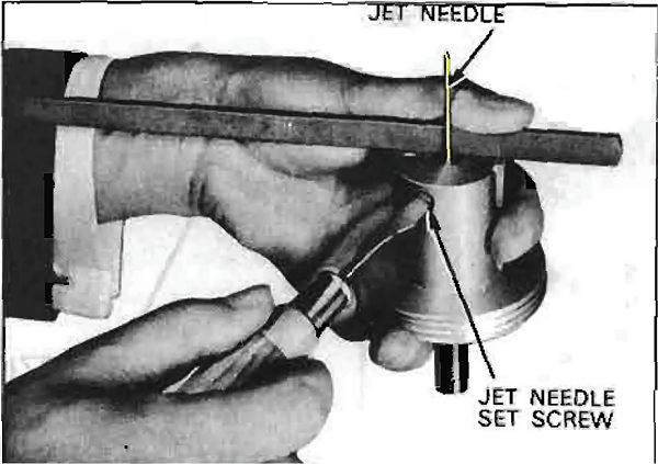
Below are a drawing and photo showing how to set needle depth in the FSM. The only difference in this technique is that the needle shoulder is above the bridge by the depth of the stand-off. When the nozzle is lowered to operating location, this should not make a big difference however, with the NON-FSM method shown above in Part 7, the nozzle top is matched against the needle's shoulder, so any mechanical differences in the sleeve, washers, stand-offs,etc between carbs will be nulled. One turn of the Idle Adjust Nut on both carbs will yield the same nozzle/shoulder gap and effectively "annular fuel orifice size".