


EScanlon
Free Member
-
Joined
-
Last visited
Everything posted by EScanlon
-
And one of the more comprehensive links, which gets quoted very often: http://zhome.com/History/DesignChanges.htm E
-
Will, if you weren't such a good paying customer I would not pick up the phone! E
-
Are you thinking 280 or Roadster, Will? The "floater" or gas tank level sensor aka tank sending unit... referred to as the "Tank Unit" on the wiring schematic, is removeable from the upper front SIDE of the gas tank, and can be removed with the tank in the car, although a bit of a PITA. Take your Right Rear tire off after elevating the car on jack stands, and you should be able to get to it. FWIW E P.S. Or were you still in Landlord/Tenant Plumber mode? J/K
-
I'll let others chime in, but IME it depends on the condition of your paint, and what care your car has received in the past. You don't really want to start using a new wax on a car that's been getting regular treatments with another formula without first removing all of the old. Conversely, if the old formula was abrasive, it's very possible that there isn't much paint left for the new wax to REALLY show it's capabilities after you remove the prior wax used. I've heard many different brands over the years, but they all share several basic traits, some of which are that it is all dependent on the condition of your paint, how well you prepare the car for it's wax job, and HOW you wax it. 2¢ E
-
The good news: You didn't have to cut out much metal....it had mostly rusted away. The bad news: The support brace that goes in front of the firewall and just visible in your 2nd photo of the first post...that's missing a section of the metal that goes under the floor pan. Additionally, that much rust in the floor pan would indicate that you need to check out the rocker panels as they may be close to gone also. The extra sheet metal you bought may come in very handy for the firewall, but the formed pieces available from Charlie Osborne may be far superior to anything else. See if you can get that lower support from him in order to re-strengthen that floor pan. 2¢ E
-
Loose wires AT the ammeter or a voltage regulator going bad. 2¢ E
-
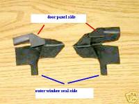
Dan; No worries on correcting me, if I goof I definitely want it pointed out. On that note, the problem with this piece is that there are actually TWO tabs. One that is the long and straight piece very visible in the picture, and the SECOND tab which gets lost in the lack of contrast and detail of the picture. I'm attaching a blown up image of that same picture with some labels put in. In my haste to answer, I didn't complete the explanation. Wick Humble's book "How to Restore your Datsun Z-Car" on page 163 in the lower left shows a picture of the tab you mention with the caption: "Rear sealing rubber must be cemented in steps. Little tab is further secured by window-trim strip" While the picture helps, it doesn't show the OTHER tab which does go under the door panel. The written description in the book reads: "Rear Sealing Rubber -- This little seal is cemented on as well. It has one specific place it fits and no other. Note that the small outer tab wraps around and secures under the edge of the stainless trim, unlike the front. Make a trial fit of the rubber and note the adhesive must be applied to different sides of the part, where it interfaces with different parts of the door and frame. Take your time and get a neat, secure bond." (W. Humble: How to Restore your Datsun Z-Car; p 163; Body Exterior & Drive Line Assembly) So, Dan, you were absolutely right to say something as I hadn't explained properly and in re-reading my post it could be said that I had it backwards. There is a tab that goes under the door panel, but not the one that is readily visible in the picture. That's where I goofed. Hope this helps. E
-
Those are the seals that mount to the REAR inside corner of the window frame as it enters the actual door body itself. Look at the inside of the corner, and you should note that there is a "step" to the rubber. This step lines up with the edge of the door frame metal and lays flat on the SS Window frame surface. The little tab of rubber that sticks out the side gets glued to the inside surface of the door, and will then protrude UNDER the inside door panel. Use a good quality adhesive, as these prevent water from entering the inside of the door plenum through the rear entry for the window frame. While 3M Weatherstrip Adhesive is quite good, you need to know how to use it well in order to have good success in this application. Due to the amount of rubbing and wear it will get when you enter and leave the car and with the door closing and hitting the door seal, it can and will rub. If the adhesive isn't used properly, it will allow the seal to peel off. 3M to be used properly, requires a very thin coat first on both CLEAN surfaces, then a second thin coat to re-activate it before it will hold strongly enough for this use. It is that second coat that gets tricky. Too much and it will literally dissolve the bond of the first, not enough and the contact will have been "dry" and won't have any hold. If you have doubts as to whether this will work for you, use silicone (and sparingly) or my favorite - Goop. Goop is like a thickened and rubberized silicone. If used properly you can even re-build chunks taken out of sneakers. FWIW E
-
Interestingly, the WHITE/RED wire is the power wire going to the LEFT Turn Signals/Stop Lamp in the back of the car. The RIGHT side wire is White/BLACK. But, and this has happened on other switches, it may be that the wiring colors on the switch side of the connection to the wiring harness have been inverted. The only way to verify this is to follow the W/R wire back to the connector and see if it's corresponding wire (on the dash side of the wiring connector) is also W/R or if it is W/B. If it IS W/B then everything lines back up again, that is, your RH turn signal is the one that is causing the heating up of the wire. If on the other hand, it's W/R then a different problem/situation is evident. In either / both cases, go to the back of the car, and check both the grounds for each of the tail-lights AND the individual bulbs and their sockets. Too many times it is some form of corrosion specifically AT the rear of the car that causes many problems up front. FWIW E
-
His license plate IS: "JOEKR"! 2¢ E
-
Check your Black White wire at the Resistor. It sounds as though it has been removed or disconnected. That it runs while you have the key in Start but not in Run is a clear indication of no power to the coil when the ignition switch is in the Run position. Also check the wires to the coil, one of them may have popped off. 2¢ E
-
New: While your logic may seem .... logical, it won't apply in a court of law. The fact is, he admitted to having backed into her...otherwise why would she have his information etc.? Without a police report, a picture, or a witness, the insurance company isn't going to believe you and ignore her claim. What has or may have transpired from that time to the present...is not in question, and unless you have PROOF of something....it's called conjecture and is not admiseable. She reported it to her insurance agency, who is now coming after his insurance company, who in turn is questioning why Surf didn't report the accident. That's why he knows that she reported it. Unless the insurance company contacted him directly....in case he did not have insurance at the time of the accident. In that case, they're probably going to seek damages from him directly as well. From personal experience, without any of the three items above....it's a slam dunk that they'll pay out to the claimant. I had the rear end of my Acura intentionally slammed into by someone who ended up with a scratched bumper...the police said to exchange information but that no police report since it happened in the parking lot of a convenience store. The insurance claim? Five Thousand plus! I HAD reported it, but they still charged it against my policy. Don't forget it may have been the slowness of her and his insurance company working together that caused the 3 month delay. 2¢ E
-
You mention you "neutral back a little bit in my daily driver", on a hill? Then you might be the one at fault for not preventing your vehicle from moving backward. Report it to your insurance company, and explain the situation. Might not help much, but... it's worth a try. E
-
For an early 73 look under dash behind the steering column, and look for a small cylinder that looks like a metal 35mm camera film canister with two wires attached...that is your relay. Easily obtained at your local parts store, although if you go to MSA or VB you can get one that has been matched for you. Later 73, look on the passenger side-side foot panel and you'll see several film canister type items. The one that is a cylinder resembling an aluminum can is the one you want. Take note that may/should be two right in the same area, the second one is for the Hazard flashers (yes, they are separate). However, do a simpler check first and have someone step on the brake and see if the brake lights go on or not. If they do NOT, then the wire is more upstream and into the turn signal switch. If they do, you've pretty much narrowed it down to the flasher or....the hazard switch. (Yes, this IS possible.) E
-
Check (in descending order of probability): A. Hazard Switch, also known as the Four Way Flasher. This is right upstream of everything you've mentioned. B. Fuel Pump (if equipped) C. Inline Fuse for the Fuel Pump. Or A & C since they're together then B. FWIW E
-
I was going off of the parts I received in a kit, not off any parts list or breakdown. It may be that the kit I received wasn't a true blue Nissan, but one of the kits sold by one of the vendors. In any case, I distinctly remember the FELT as being plain old compressed and cut felt. It was a gray color. The rest of the weather stripping was rubber covered by a "felt" type finish, but rubber underneath. This may be a situation of where they inadvertently inverted the names. Anyone else who has put on these window seals and can confirm / deny what has been discussed, please chime in. E
-
That pic doesn't show both sides of the "drum" or the resonating plate which is what vibrates rapidly and creates the "honk". But it does help. Could you confirm if the paper is on both sides of the resonating plate? IIRC it IS on both sides, but what it does is to simply act as a soft holding material that allows the metal in the resonating plate to vibrate and emit it's tone. Similar to a guitar or piano string. Both sides of the metal get held by a softer material that allows the metal in between to resonate within the two points. On a plate such as this, it acts as an inverted speaker, which is essentially what it is. To replicate it, you can get a folder, not the pale yellow one (Manila folder), but rather the one that you put the manila into in the file cabinet. Usually these are dark green, although I've seen brown and even fancier colors. The point is that THAT paper is perfect for this. If you then wish to make it completely waterproof, just put the paper in between wax paper sheets, insert between 2-3 sheets of newspaper and using your clothes iron, heat it up past 130°F (55°C) it's meltpoint, and iron away. Enough of the wax will transfer to the paper to waterproof it perfectly. Some people just use the paper without waterproofing, and generally it isn't a problem. However, it CAN absorb a dash of moisture which is why that paper you see on the horn is originally similar to a waxed thin sheet. FWIW E
-
On the subject of Carl's posts, I believe many were salvaged from old archives before he passed. Dont know if all of them were. E
-
Carl: You've got it perfectly, but you've reversed the terms. The FELT is a formed piece from a straight piece of felt that has had two grooves cut into it. Those grooves are where the 90° bend goes to fit it into the channel. The grooves in essence then go on the "inside" of the U that gets made when you fold the felt. It gets placed on the lower portion of the rear window guide. The RUBBER gasket, which has a "felt" or "fuzzy" surface and may be part of the confusion , starts immediately above the lower felt, up to the corner of the window frame where you will note there has been a "notch" or 90° angle cut in the rubber leaving a small connecting piece on the "floor" of the gasket. Sometimes this piece will come with that corner already glued, but you would have to cut it if you buy the weatherstrip channel in bulk length. The rubber then continues across the top and down the angled forward portion of the channel all the way to the end. Proper installation is critical as it's easy to NOT do something that later causes problems. Most common is to NOT glue either the "floor" or one of the "walls" of the channel and then have it interfere with the window glass, or worse not make a good seal. I have a small paint stick that has been whittled down to just fit easily inside the channel and still allow me to slide it along it's length. Then I use the 3M Weatherstrip adhesive in black and lay a medium width bead from the corner to about the middle of the frame down, then with the paint stick I spread the adhesive carefully along the bottom AND sides of the channel. This gets repeated on the other side of the corner. Then once that's done, I insert the corner of the weather stripping by carefully pinching it closed. Then, again by pinching, you then insert the weather stripping through to the end on each side. The weatherstripping generally has enough "bounce" in it to pop back into shape once inserted and then you can (if possible) slide the actual window glass into the frame. This will spread it to the full thickness of the glass and apply pressure to the glue/rubber contact area. The felt gasket gets applied in the same manner to the lower edge of the frame. I leave this for last since you won't know until you have the rubber gasket in place where exactly to place it. FWIW E
-
You will need a long necked funnel. One of those funny looking ones that seem to have this long tube that ends in a 1/2" to 3/4" wide tip. Once you've checked the ATF, use the same tube the dipstick fits into to put your funnel into and then add if you need some. If your AT is running sluggish, etc, it might need to be taken to an AT specialist and have the fluid changed. If that is the case, and you plan on doing that, it won't hurt to use one of those AT "fixes-in-a-bottle". I've used a product by Lucas for leaky ones, and another one by the "GUNK" people that helped my transmission which claimed to be a "sludge remover". One note, the "sludge remover" just dissolves the sludge and opens up passageways, BUT because it DISSOLVES the stuff, is why you don't want to run that stuff forever....get the fluid changed. My point is that by running the stuff for a while before you get the fluid changed, you will have "flushed" the passageways of burnt and clumped fluid. FWIW E
-
I think I know what you're referring to, but it's been years since I disassembled a horn. Can you post a picture? E
-
If it is indeed "Synthetic Rubber" then it may be one of the newer silicones or even rubber replacements which for the most part ARE fuel resistant. Note the "most part". Will's point is dead on. Put it in a glass jar (so you can see through the sides) with some gas. If no change in either the color of the gas OR the shape and thickness of this part, then it should be (note the SHOULD BE) okay to use. 2¢ E
-
Ditto on the not willing to dump $30, 30 days in advance for a show that is a bit "uptight" about signing responsibility waivers. Anyone living in the PAC-NW knows that the weather is just a bit too unpredictable this time of year to make such concrete plans. Add that there are no Day Of registrations and it just shows they're trying to exclude those who don't trailer their car down (i.e. drivers). Blue Lake in August, or even the Beaches Cruise-Ins (weekly on Weds @ PIR) are by far MORE fun and MORE of a "deal". I'll get better info on Blue Lake and post it. Anyone that knows anybody on the Datsuns NW club, you might clue them in that if their intent is to EXCLUDE other clubs, then all they need to do is NOT advertise the show. Purportedly, the intent is to "define" the classes of vehicles registered in order to have trophies for each class. The problem is that intent is one thing, and the public's perception may not be so benevolent. 2¢ E
-
Will: While your repair may seem minor, in my experience the possibilities of getting back to the area "in a short while" usually ends up being YEARS later. That means that that "cosmetic" repair, is akin to using speed-tape over the hole and painting over it. Fiberglass has no rust-proofing properties at all. In fact, if there is ANY rust on the surface you apply it on, it will continue to rust very happily protected from the environment....but still rusting. If you etch the metal, then you may prolong the amount of time before the rust starts / continues to rust, but there is NO rust-proofing going on here. While the comment about POR being difficult to remove is appropriate....after all it is due to this tenacious grip that it is such a good product...it doesn't address that it CAN be removed. Whether by grinding, sanding or by using the stripper sold by the POR folks, it CAN be removed and you can then proceed to further bodywork. My concern with Nate's rocker panel is that what is NOT visible is how far gone the rocker and dog leg are. This may make both of the processes in discussion a totally moot point. If he had reported that he had seen the inside of the rocker and dog leg and said there was no rust there, then it might be a different story. As it stand, in my experience and I know a LOT of us here share that experience, that dog leg is close to GONE. The rocker may or may not be in the same shape, but I'll wager that it may also be failing. The possibility of saving any of that metal for any length of time is going to be strongly dependent on the type of repair you attempt. The PROPER method...is metal replacement. Nate has said that that is not in the picture now, so obviously time and money must be a consideration. So, which repair is the "best"? Well, to address fiberglass and it's application and further bodywork required: 1. You'll have to grind ALL of the rust off and leave a ground surface that has extremely rough even sharp scratches in it. 2. Then you need to tap in the metal deep enough to accept the patch and give you area to blend the repair in smoothly. This means literally taking a hammer to your car to pound that dog leg's surface in. Be careful as you could cause OTHER problems. 3. Apply your fiberglass, and hope you get some in to the inside of the metal which is where the rust is coming from. 4. Sand and smooth the fiberglass, and apply bondo or surface filler as needed to blend in the repair. 5. Paint. The POR method I'm suggesting is: 1. Degrease with Marine Clean both the outside and the inside of the rocker. This does entail removal of the interior vinyl and the seat to give you room to work, but it will make things a ton easier. It will also make it easier to rinse the MC and the MP. 2. Etch the metal with the Metal Prep and rinse, then allow to dry. If you wanted you could blow air into it or apply a heater to speed it up. 3. Put some tape on the outside of the dog leg. This is to build a "dam" which will stop the POR from just dripping out. 4. Spray the POR into the rocker with a syphon spray nozzle. This is a simple air nozzle that has been fitted with a venturi tube at the tip to allow it to suck up fluids and then spray them. I forget the part number but it's readily available from Harbor Freight. 5. When set, remove the tape from the outside. 6. Now when you look at the holes from the outside, they will be very close to the surface of the surrounding sheet metal. Now the repair will only be using a very thin skin of bondo to finish the repair, and allow you to go to paint. Years down the road, the fiberglass will literally....fall off. And it's true that it's removal will be greatly simplified. In fact, it may take the REST of the metal that is there now, in the form of rust dust. There won't be much "cutting" of the metal, it will be so corroded that it will simply be ground off. Then you have to hope that the surrounding structural metal hasn't been compromised by the rust you left behind in not treating the interior of the rocker panel. This simple "cosmetic" fix may leave you needing major transplant surgery later....or even cause the car to be junked. The POR on the other hand, unless it doesn't live up to what I've currently experienced, WILL require the metal to be cut out. This is because the metal will have been put into a state of "suspended animation" by the POR. Having metal there that can be cut, whether by a shear or a cutting disk, is much more preferable than to grind the dust off. Then, if necessary, you use the POR stripper they sell and remove any remnants of the POR you need to remove, and continue with your panel replacement....on steel that is still relatively sound. Yes, this may be more towards a "permanent" repair, but it won't be the lick and a promise that the fiberglass repair would be. I was taught to do the BEST job you could do, at that time, for the amount of time and money you could devote to it. There will always be additional things you would like to do, and time and money you would like to devote to it. Doing a half-baked repair is a guarantee of further problems down the road. So, FWIW E
-
I've used it and I like it. Search under POR-15 and you'll find tons of information. You might also send an e-mail to Bruce Palmer at info@zerorust.com he sells a product called Zero-Rust which has had some good reviews. FWIW E
