


EScanlon
Free Member
-
Joined
-
Last visited
Everything posted by EScanlon
-
 Original Article Enrique Scanlon (2004) - Revised & Expanded with Bob Kroshefsky (2011) Pictures by Bob Kroshefsky (2011) P/N Breakdown by Bob Kroshefsky (2011)Free
 -
TY would like to know about the spotlight and the ZCON thing
-
To all this is his wife Deb TY for all the kind words-would love to print this but Enrique was my computer man so don't know how
-
Proof positive of why they call the area the "Rust Belt". E
-
And I've seen it done both ways... over the rubber and cutting out the rubber. E
-
You have it on right. The short leg goes towards the inside of the car. As far as installation, make sure you have the proper screws that screw into the tabs on the window frame, if necessary run a thread chaser to ensure that you're not fighting a bit of old rust/corrosion trying to get the screw started or tightened. Next, use a lubricant all the way around the gasket and opening. I personally prefer food grade silicone, but then I have a neighbor who works / services food equipment. Dishwashing detergent can dry out if you take too long, but if you water it down it can stay slippery for a good long while. I wouldn't use an oil nor grease, they'll attack your gasket / paint. Now comes the fun. Ideally you should have a friend help you hold and press on the FRAME of the glass (not the glass) and press not only on the frame IN towards the interior, but also on the front part of the frame towards the BACK of the vehicle (insert the wedge so to speak). When he gets it into place, you should be ab le to use one hand to push the rearmost apex of the window IN so that you can get the screw started. Start the screw and only go two or three turns, don't tighten it at this point. All you want to do is get it started. Once the rear most is started, address the next one, whether above or below and do the same.... just get the screw started. Once you have all the screws/washers started, then start tightening down EVENLY and keep an eye on the whole assembly. You do NOT want to snap a screw nor strip it. The reason you're having a hard time is that you're dealing with new rubber. If it were going on easily, it wouldn't be making a good seal. Hope this helps E
-
Have it e-mail you to re-set your password using the e-mail address you used to register here. Some of the accounts have had that problem (I did as well) but once you re-set your password it works fine. E
-
First, classified ads do not go on THIS website, they go here: DatsunClassifieds.com Next, once there you log in with the same user name and password as you did here. Then just below your user name you should see a line that says "Create Ad" and you're off. E
-
Insert a plastic or wood pry flat bar in the slot on the rear side of the emblem (they're sided, open edge faces to the back) and then work your way around the car slowly. E
-
And your caution is duly noted. However, this is by no means the first time that this has been asked, nor the first time that it has been discussed. Aside from that, by the time they have the car disassembled to the point where they can see what is needed to remove the lock screws, it doesn't take a lot of genius to give up and just use a drill and a bit. So, while your caution is admireable, the public berating you've bestowed upon Steve, would have been better in a PM than in the open. E
-
And nobody in Phoenix knows the old art of metal bumping? Can't help you as far as how much to replace, I usually bump out the metal and oftentimes end up with a minimal skin coat of bondo. FWIW E
-
And Thank You for understanding. I wasn't trying to place the blame on you as much as saying..."Do you really think so?". Glad you got it resolved. E
-
Post some pics. Otherwise you're expecting everyone to presume that you've assumed which weatherstrip goes where. You may be spot on, but one of the weatherstrips being ~short~ in one of their kits is totally unheard of. After years of doing this, that they got one short, as opposed to your having misconstrued the fit or misidentified it's use... which one would you think is more likely. I'm not saying that they've never made a mistake, just that the odds aren't there. FWIW E
-
I'll check into those gator tools, there is an outlet listed just into Portland. Thanks Capt! E
-
Excellent tool ingenuity! I'd be interested in finding out if you would sell a duplicate. E
-
What your mechanic actually wiggled was the Ignition SWITCH BODY HALF itself and not the connector nor the metal part connected to the Ignition Lock. By wiggling the Bakelite half of the switch, he moved the electrical contacts mounted on it so that they then made contact with the contacts on the internal switch lever (connector) and then was able to start it. Remove the Switch from the Lock via the 2 screws that hold it attached and then see if the brown bakelite half can swivel with relation to the metal half. It should NOT rotate at all, but over the years the two will have lost their grip to each other and can then slip out of position. It is this rotation that is causing your contacts to be intermittent. That the Ignition CYLINDER is hard to move is a function of the KEY LOCK and not of the Ignition SWITCH, although it is conceivable that the Switch is the reason for your cylinder to be having the mechanical resistance to turn. Once you have the switch off you can then determine if the cylinder needs servicing (lubrication) or locksmith attention. Don't use WD-40 here, check with Unkle (another board member) for what he recommends, but WD-40 will only be a momentary fix that can leave you with more problems later. I've used Graphite Oil, but have heard that Locksmiths have better lubricants. Replace the Ignition SWITCH. This is a fairly common failure amongst these 40ish old cars, and often the source of a lot of electrical gremlins that defy normal / standard diagnosing. Once you do that you can then diagnose accurately if the problem lies elsewhere. Use Occam's Razor for diagnosing/ fixing these cars... find the SIMPLEST explanation that covers the facts rather than the most complex. More often than not, that will get you going again. FWIW E
-
Excellent video link! I think the only one that has really used them properly is Alan T., and while I can't claim to now be "in the know" hopefully I won't be so "rude" as the video says. Thank you Blue-Sensei E
-
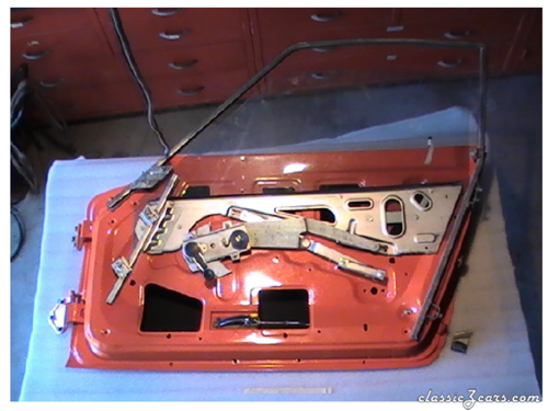
I usually hold off to allow others to chime in, but the game(s) must have everyone distracted. The plastic piece you have in two pieces is usually on one of the rollers for the window mechanism. Nice to have, but I don't think you'll have much trouble for not having it. Best I've been able to discern is that it's to either keep the roller in the track on the window pane, or to keep the roller under a slight amount of pressure and therefore in line in the track. Others may have a better or more accurate explanation. As far as to why you're not locking now, it may be that the position of the lock and / or the tab on the back side has shifted sufficiently to NOT allow the locking mechanism to travel properly or to be just short (or long) and therefore not permit the lever to rotate. Tried your video, but it didn't play for some reason. I'll try again later and maybe I can offer more,. After getting it to play, I can't offer much. Check that you have a Left tab on that lock and that the shaft on the lock isn't too worn to properly actuate it. Hope it helps. E
-
I can't recall all the details, but if memory serves you may want to post a picture of your actual hinge. The reason being that there was a change in the Lock-Tab (again if memory serves) that changed the configuration of the hinge from the earlier to the later hinges (240). E
-
Just a thought for you, the majority of members here aren't conversant in ?? text speak? Spell things out and use proper sentences and grammar and you'll find that everyone can understand it. FWIW E
-
Gorilla Glue in my experience is hard to control as to where it goes and then when it starts foaming, even more difficult to keep in place while it sets. I would recommend a product called Shoe Goo, Household Goo, or other XXX Goo. Think of it as Silicone on major steroids. Where silicone sticks and is hard to tear off, this stuff grips and you need pliers to even tear it, and even then it's hard to peel off. One might think that this would make it problematic, and it can be if you aren't familiar with working with silicone. However, if you are familiar with silicone, and remember the old spit on your finger to smooth it out technique, this stuff will please you to no end. I'd check your local hobby store and see if they still sell those styrene plastic "beams" and other straight pieces. One of them, if memory serves, is as close to a "C" channel as can be... but in miniature. Again, IIRC, it's available in various widths. Find the one that's closest to the width of the channel you're hoping to extend and then glue it in position with the Shoe Goo. Smooth the transition from one to the other and you should have a properly extended drain. FWIW E
-
Your car may have originally used the earlier variation which did NOT have the metal strip the later style had. I did this to my 71 by changing the quarter window frame completely so I can't say how to modify an early to use the later style, maybe some one else has and will post. FWIW E
-
I've had my soldering iron for over 30 years. It is a real "old-timer" as it was used when I got it. I did find the right style / wattage / size on-line, but was surprised at the price: http://www.all-spec.com/products/3138-150.html?gclid=CLKhqovP2rQCFQVcpQodqGYA5g I also found a vintage one with the right wattage although the style of the tip / body is somewhat different: http://www.etsy.com/listing/100844855/vintage-150-watt-drake-soldering-iron?utm_source=googleproduct&utm_medium=syndication&utm_campaign=GPS&gclid=CO62so3P2rQCFcZfpgodlzgAbA FWIW E
-
The solder technique of sealing holes works best with: a) Acid Core Solder Tinning liquid c) a nicely cleaned hole and small part of the surrounding (just past the exterior of the hole). If necessary you want to "ream" the hole to make sure there's no rust or schmutz inside it. Apply a drop of Tinning liquid to the hole, then heat up your iron and once it's hot, insert the tip into the hole and sweat the solder into it. Once the iron is warm, you can usually do these in 20 seconds or less (depending on the size of the iron and hole). I can usually seal all the holes on the side of a vehicle due to the rivet-on vinyl strips, in less than 5 minutes and most of that time is spent moving the equipment from hole to hole. Emblem holes can be done, but they require that you can literally "sheet" the solder across the hole, meaning that you carry the solder from side to side. This is where having a small area around the hole without paint and also tinned becomes critical since without it it is darn near impossible to "gap" the hole. But I agree with Ron, for hidden holes that you want to seal, JB Weld, or some epoxy would do it. Just don't use Bondo, it's porous and will soak up humidity. FWIW E
-
Do NOT under any circumstances, opportunity or manner of thought go test ride a Datsun Sports Roadster. That's it, it's all the warning I'll give, and if you know better you won't delve into it. Nuff Said. You've been publicly warned. E
