EScanlon
Free Member
-
Joined
-
Last visited
Everything posted by EScanlon
-
 If you note the "foggy" look of the black paint, that is what POR will do when exposed to UV light (sunlight in my case). The uneven cut-off line to the right was to minimize the amount of visibile POR when you have the door open and the fender on.
 -
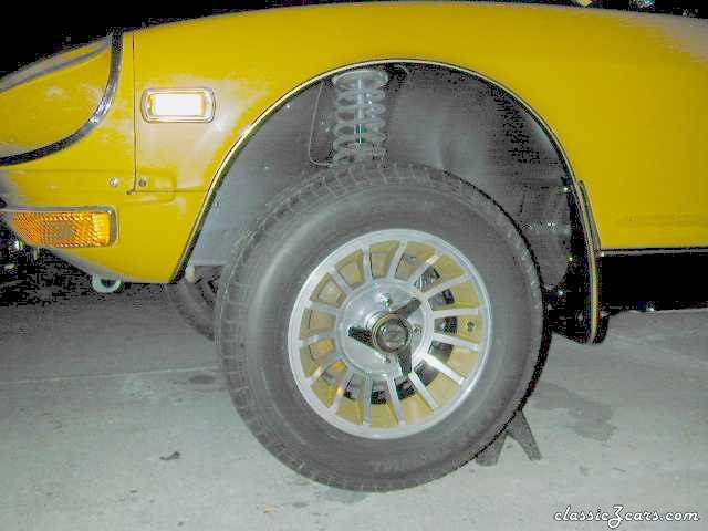
 This shot shows how neatly the PVC hose will fit in the opening between the rocker, the fender and the splash guard. This is important, because although Datsun did expect this opening to be the drain hole for the cowl, they forgot about leaves and other debris which eventually clogs it and causes the fender to rust. By directing the cowl drain tube to drain out, you minimize the amount of water / debris to accumulate back there.
 -
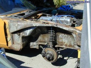
 Actually the car was so eager to get OFF the jackstands that it was doing wheelies. The car had been on and off jackstands for at least a couple of months by this time.
 -
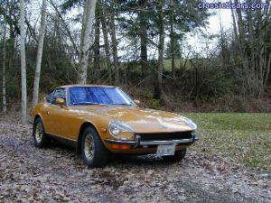
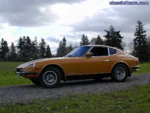
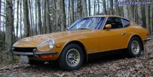
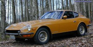
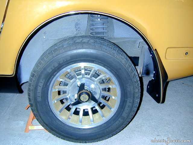 Look closely at the fender lip and you'll note the pinstriping that was added to set off the black rocker panel and splash guards.
 -
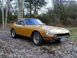
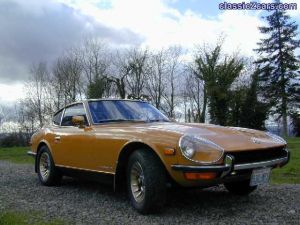 Thank you, this is one of my favorite fotos.
 -
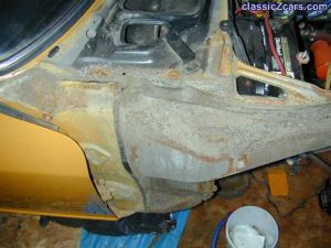 If you look at the pattern of the dirt and rust, you'll note that it is exactly where the tire flings dirt, mud etc. The outer boundaries of it, show the rust forming.
 -
 This shot is actually after I'd started removing undercoating and other loose debris. Look just below the front end of the valve cover and you'll note the tell tale color of rust, that was from the clogged fender drains.
 -
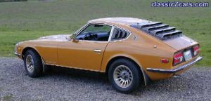
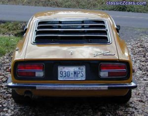
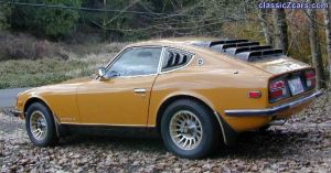
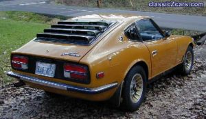 The quarter window louvers were an aftermarket option that I discovered on e-Bay. Since I wanted the back end of the car to be covered up, so as to not fade the carpet, I thought it went hand in hand with the hatch louvers. Both louvers are painted in Metallic Black and pinstriped to match the car.
 -
-
-
-
-
-
-
-
-
-
-
-
-
-
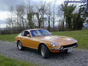
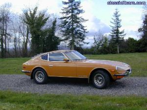
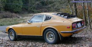 Left Side Shot of the Car, now finished.
 -
-
Take a look at what I found!
-
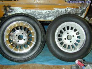 Pic showing damage to the rear valance. Also a shot of a pair of wheels, "before" and "after".