


EScanlon
Free Member
-
Joined
-
Last visited
Everything posted by EScanlon
-
Center cap is going to be tough, I found a similar wheel at Dayton: http://www.daytonwirewheels.com/classic.html But the center cap doesn't have that additional ridge yours seems to have. You could try calling them, but in my experience if it doesn't have Dayton stamped on the wheel (backside) they'll just tell you it's not their product and that's it. They won't hazard a guess or anything. But, it might give you something to begin with. E
-
Carl; When I read this, my thoughts were that he was referring to either it's "code" name or it's "project" name when in the design/ prototype stages. He may be referring to the story that the Z was named for it's "project" name because Fairlady wasn't acceptable to the US market, or the story of where it was named Z because it's the last letter in the alphabet, another variation being that Z is the last letter of the Japanese alphabet... which is ludicrous since they use symbols and not roman letters. Maybe this will help E
-
As a thought I was going to suggest getting a length of all-thread to replace the rod, when I remembered that one end of the existing rod is left handed thread and not right hand. So, as an alternative, what about a section of tubing, preferably steel for strength, that has an inside diameter equal to the diameter of the rod. You would cut your rod with a pipe cuter to avoid a sharp and flared out edge, then fit a section of the pipe to lengthen your existing rod by the amount required. You could also pre-bend the pipe to fit the required radius bend, then cut and fit the rod. Then either solder or braze the rod/pipe together or if not able to do that at least crimp the pipe onto the rod and use some of your JB Weld. Just a thought. E
-
Let her shift, she is a "pro"..... and she doesn't use reverse..... E
-
Check the wiring at / by the connector. There MUST be a connection for that wire, if not, send it back to MSA and explain the omission. You can determine where it should connect to if you compare the old to the new fuse box and see where the wire connected to the old and then look for a connection on the new that leads to the same area. HTH E
-
Arne, the main connection for the battery to the fuse box is through the Fuse Link (it's the only connection) and that wire is the White visible in the lower right of the inverted fuse box. E
-
That White/Red wire is either the direct connection from the Alternator or the one that connects to the Ammeter. So it's not really an "infamous" wire. Without it you won't have Dome or Engine bay lamp, Instrument Lamps nor Parking Lights. The MSA Box should have some provision for receiving that connection. FWIW E
-
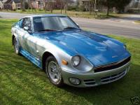
http://www.classiczcars.com/forums/showpost.php?p=254807&postcount=13 While the car in the pictures there was overdone, by using too many colors and subtle graduations, the general paint theme -- without all the stripe shading -- can look very good. The main problem, to my eyes, is that that painter got ... carried away with their own concept. It's easy to do. The subtle fogged in stripes that repeat other themes or bodylines or mods (window louvers, indents in rear spoilers, triple Maverick side lamps, double hood "bump" striping) when done in moderation can lend and actually highlight body lines, mods and lend subtlety to otherwise bold changes. When the effect is as this car was done, it's like watching a 13 year old girl's first attempt at putting on "adult" style make up. Too much lipstick, in too dark a shade, with overly dark eye shadow and rouge and mascara to make a clown laugh.... This car would have been better done if the painter had stepped back 20 feet and seen that it was starting to get way too busy. Then again, there are folks that want it busy and bold. 2¢ E
-
You might also check that all the wires were properly seated in their cups. That was the problem on another dizzy problem. The coil wire was in it's cup, just not deep enough that it made good contact with the button's contact. E
-
I'm at a loss to understand the legerdemain you're describing. The 5°C difference is about 9°F; while that can be the difference between boiling and not, or freezing and not, in normal operation if your water cooling system temperature is close to either one of those values you have a problem. A second temperature gauge isn't going to alleviate that problem nor will it avoid it, regardless of it's accuracy. A more accurate temperature reading is important if you have a process which must occur at a specific given temperature, or be avoided otherwise. Thermostatic switches for use with the majority of electric fans are NOT calibrated to the umpteenth decimal, so if it actually kicked on at 187.7°F vs 185.036°F vs approximately 180°F is of little to no value other than data. The important thing is that it DID kick on at approximately the temperature it's rated for. If it does NOT, that is a different problem. If you're having a problem with it kicking on/off at more than 10% of it's value off from the temperature it's supposed to be operating at, then replace the switch. If the stock gauge indicates a rise or drop in temperature, having the second gauge would be beneficial only to confirm that the stock gauge is or isn't operating properly. But having the "actual" temperature down to the 6th decimal.... to what end? Then again, there are folks who jog with those watches with the miniature EKG, Pulse, O2, and Breathing sensors so that they can accurately describe at what point they ..... to what end? But to answer Troutman's original question: The second gauge would likely require it's OWN temperature sender. Connecting it to the OEM sender may in fact render both totally inaccurate or non-operable. The OEM gauge works on resistance through the sender, by adding a second wire to the sender's wire you are going to change the resistance reading. Additionally, the resistance range in the OEM sensor may be incompatible with the sensing range of the new gauge. Ron's pointed out a schematic for operating a pair of relays to run two fans at different temperature settings. That sounds different than what you are currently doing, but maybe not. HTH E
-
 Officer? Why is it you need to frisk me again?
 -
Except that the hook tool in the hand of most novice users = torn and ripped weatherstrip. Use the Rope in the channel "trick" and you won't have the same problem. That's the way that I've replaced a couple and also the way the FSM recommends. FWIW E
-
I've heard of using a latter rod from a 280 or so (going by vague memory here) and that it already has that bend in it. 2¢ E
-
One of the biggest problems is where you live. That car has undoubtedly seen many miles of salt-brine spring slush and winter ice-slush. Can it be saved? Yes, but only by addressing each and every area patiently and completely. Is there a cheaper way? Possibly by starting over with a car from out the south-west. California, Arizona and New Mexico cars are not normally exposed to the salt-brine baths of the Rust Belt (there's a reason for that moniker). But cheaper in what respect? Cheaper as far as the metal replacement and work you'll do. However, expect to spend a chunk on any and all vinyl, plastic and rubber pieces on the car anywhere. Where the dry climate is great for metal, it destroys soft pieces. Unfortunately in the East half of the USA you can expect to pay an extreme premium for a Z in good condition and a trouble free one is likely to be out of most young people's budget....heck, it's out of most ANY body's budget. FWIW E
-
Emphasis mine.Bob: That's EXACTLY what I've been telling people here for years! Personally I hope that you DO get that and more! More to the point, I wish I had the money to bid on your car, but I don't, but if your car goes up in value, mine, even not being a VZ program car, nor even in the same "class" would go up in value too. I agree with the individual that mentioned that the real detriment to Z prices going up are the Z owners that nay-say any increase in their value. I'm not planning on selling, but I do want to garner a bit more respect for my car at open marque cruise-in's. FWIW E
-
That's surely due to this picture: http://www.classiczcars.com/forums/attachment.php?attachmentid=15045&d=1163612617 But I can assure you that it isn't "regular old epoxy", regardless of what the picture seems to portray. SEM Bumper repair, IS mixed from two halves, but after curing it does retain a rubber type feel to it and does bend to a degree. "Regular old epoxy" and I presume you're referring to something such as JB Weld, or the like, cures HARD. 2¢ E
-
And yet another one..... E
-
Other ones: While I Am There I Might As Well For What It's Worth E
-
The Swivel Studs are used by Roadsters, except instead of the self-tapping screw, it's a machine thread w/nut. The Roadster guys refer to them as "Twisties", while the "Posties" are the "Lift the Dot" Single Studs, also with machine thread. Thanks for the link; Enrique
-
There are a few posts on the horn mechanism. Do a search to do some more research. But, in a nutshell, it sounds as though the horn wiper contact, the one behind the steering wheel mount isn't making contact everywhere on your steering wheel hub. Cause could be a crooked mount, or missing copper on the contact plate. FWIW E
-
Carlos; If you do not connect the wires that normally connect to the BR to each other, the coil will NOT receive power when the Ignition Switch is in the RUN setting. That is, you may get a spark to START but as soon as you let go of the key and it returns to RUN it will stop. So, to recap, connect the B/W and G/W wires that normally connect to the Ballast Resistor to each other. Now as far as timing. If you have indeed checked that the #1 piston is at the top dead center on the compression cycle, then the rotor should be pointing at the plug wire going to the #1 cylinder. Checking #1's position is easy once you know this trick that Gary (Beandip) explained to me: Remove the spark plug, (and also the distributor cap so you can keep your eye on it) put your finger over the hole to seal any air going in or out. Crank the engine over by hand using a ratchet on the main crank bolt. When you begin to feel pressure building up under your finger, the compression stroke has begun. When it reaches it's strongest point you may not be able to keep your finger in place, but that's ok. Now take a look at the rotor on the distribuor and note it's position as that is the #1 spark plug. The rest are based on the firing sequence: 1-5-3-6-2-4 and the distributor moves counter clockwise. (Was it Bambikiller that came up with "Too Young, Too Old, Just Right! as a mnemonic to remember the sequence: 15-36-24?) Check this FIRST, as it's a "basic" item. You may already know all this and if so maybe it will help the next person to read your thread. HTH Enrique
-
Use the proper product from 3M to get the best results: http://solutions.3m.com/wps/portal/3M/en_US/3M-Super-77/Super77/SprayAdhesive/Product-Selector/ Plug in METAL as your first surface and FLEXIBLE FOAM as your second. You'll get 3M 74, 90 and 73. FWIW E
-
Bo; No doubt you used the Spray on Chrome Paint (Krylon IIRC). Pretty nice stuff, I've used it myself on another project and have even applied Candy over it and it looks quite nice. I can see the Chrome Spray's benefit on the Front Turn Signal backs as there are times when the reflector (if it is still there) is either rusted, de-laminated (chrome layer gone) or simply missing. On mine, I was lucky in that I only had a small area or two that had delaminated and they took well to metal polish, as such all I had to do was apply some metal protectant (not polish). I did, however, paint the flat surfaces of the backing with the Polar White paint. Same with the tail-lights. I've had people think that my lights are on ... during the day. The key with the Chrome spray paint is that it allows the aluminum particles to align well and essentially "skin" together forming a mostly continuous surface. That is probably the key requirement for good reflectivity, and the reason we polish metal, glass and even painted surfaces. Silver paints alone don't do that, and trying to sand them smooth generally does not generate that evenness. In fact, sanding silver is a general PITA as it can quickly show "layers". But to highlight my point on Silver being "Grey", spray a scrap piece of metal, wait till the silver dries and you get a nice glossy and shiny finish. Then spray it with Clear. The end result is ... Grey. FWIW E
-
Stephen .... EXCELLENT!!! Thanks, Enrique
-
Roger: While lots of guys have made some attempts at using LED's and trying to get the angle just right; removing the green lenses, and even trying light up instrument faceplates, I think my solution is the easiest and biggest bang for the buck. No offense meant to the other guys, but if you're not looking to change the color, add special effects, or wanting to be blinded by your dash, then try my method. I simply painted the inside surface of the instrument cans with the brightest gloss white paint I could find. I used a paint called Polar White that commonly gets used on the underside of R/C Car's Lexan Body shells. Since it's white and glossy, it reflects every bit of light that shines through the green globes inside the instrument cases. I even use my rheostat to turn DOWN the brightness. There's a couple of points to bring up: Silver paint has been touted, however, in the color wheel scheme of things Silver is Gray. Additionally, most brush on silver paints that I've seen aren't very reflective. Spray can paint can be, but now you have to remove EVERYTHING including the green globes AND still mask in order to use it. However, most silver paints still don't reflect light as intensely as bright white does. Add to it that the green globes are actually filtering the light so that it is tinted green and you've reduced the actual light being reflected ... off a grey surface. LED's are bright, but they are also very directional. The end result can be bright areas on parts of the edges, but they don't "fill" the edge as well as the bulbs did. I'm sure someone has done a few tests, but even after the savings of never having to change those bulbs again, the initial expense is such that I'll stick to the OEM style bulbs. I bet the LED's would also benefit from painting the inside of the cases. Speaking of the OEM style bulbs, forget the 3 watt bulbs, get the 3.5 or 4 watt replacement. I recently used Sylvania 53BP, although I recall 67's also being good. I'll have to double check. I think you need about a dozen total (2 each Tach and Speedo, one each "eyebrow" instruments, 2 turn signals, one high beam and one brake). I swapped bulbs simply because many had already burned out, and I decided to start with a fully new set. I think another 30 years will be fine for my investment in bulbs. But that's the simple fix I have. HTH E P.S. The diagram came from a Clymer's manual, but IIRC I also saw it in one of the FSM's out there. There are a couple more diagrams showing all the connectors in the Engine and Rear of the car as well as the Single Wire connection Diagram. I've uploaded them here before. Do a search on posts with me as the author.
