Everything posted by CanTechZ
-
 That's good news, hopefully the threads are the same. Let us know how it works out.
 -
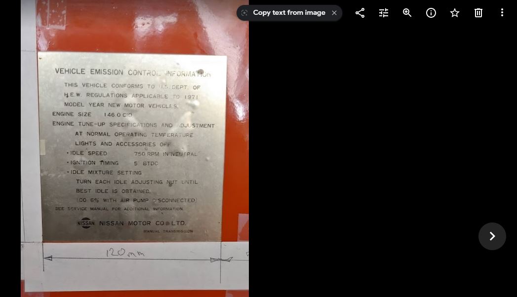
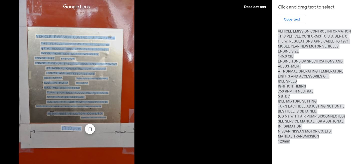
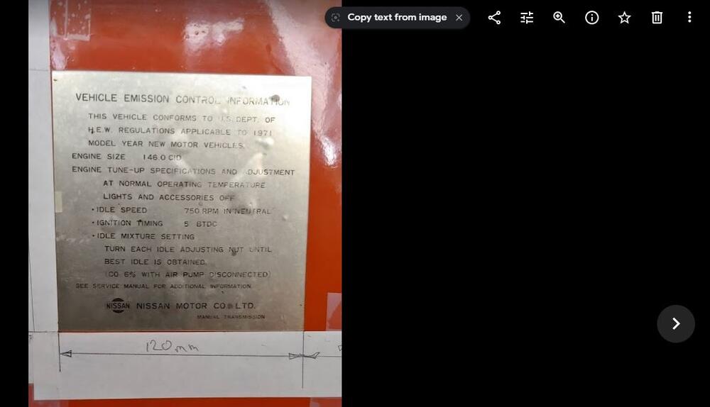
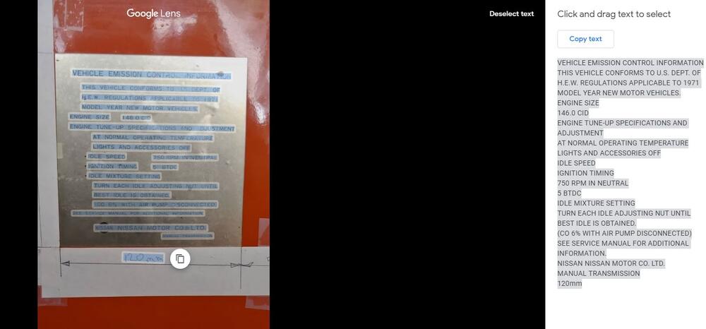
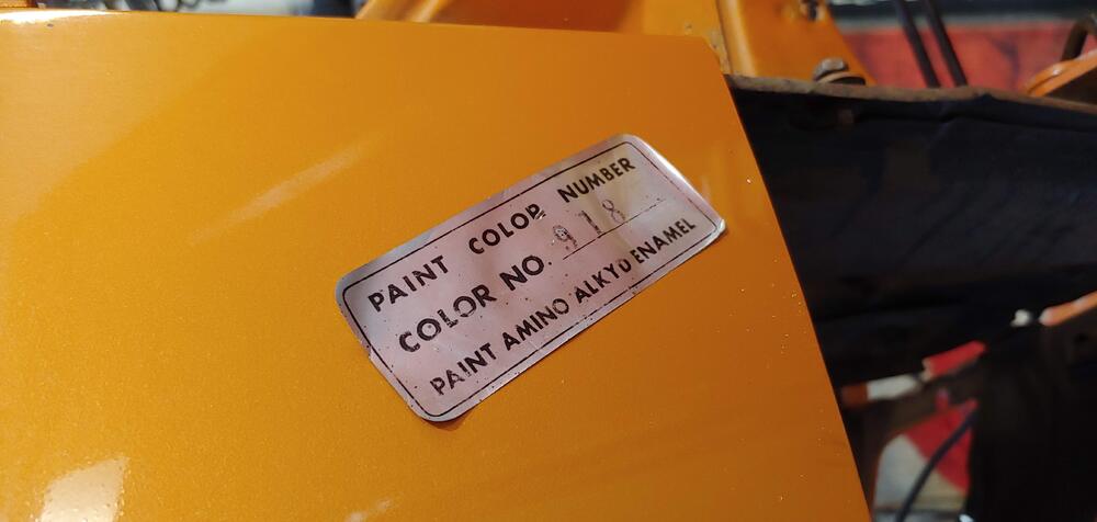
While reviewing the pictures I took of my decals on my computer using Google Photos, I noticed a button on the screen reading "Copy text from image". It's only there if the picture has text. So I clicked the button and found that it uses Google Lens to select and copy the image text to your clipboard. I was very surprised at how well it worked on an image that had glare on it. I will have to learn what else Google Lens can do. This would be very useful to extract the text if you were creating your own decals.
-
My 7/70 looks to have similar clearance to the shock tower as yours but my Brake M/C has the bleeders on the opposite side. Here are a couple of captures from a video I did of my car before I took it apart for the resto I currently working on.


-
-
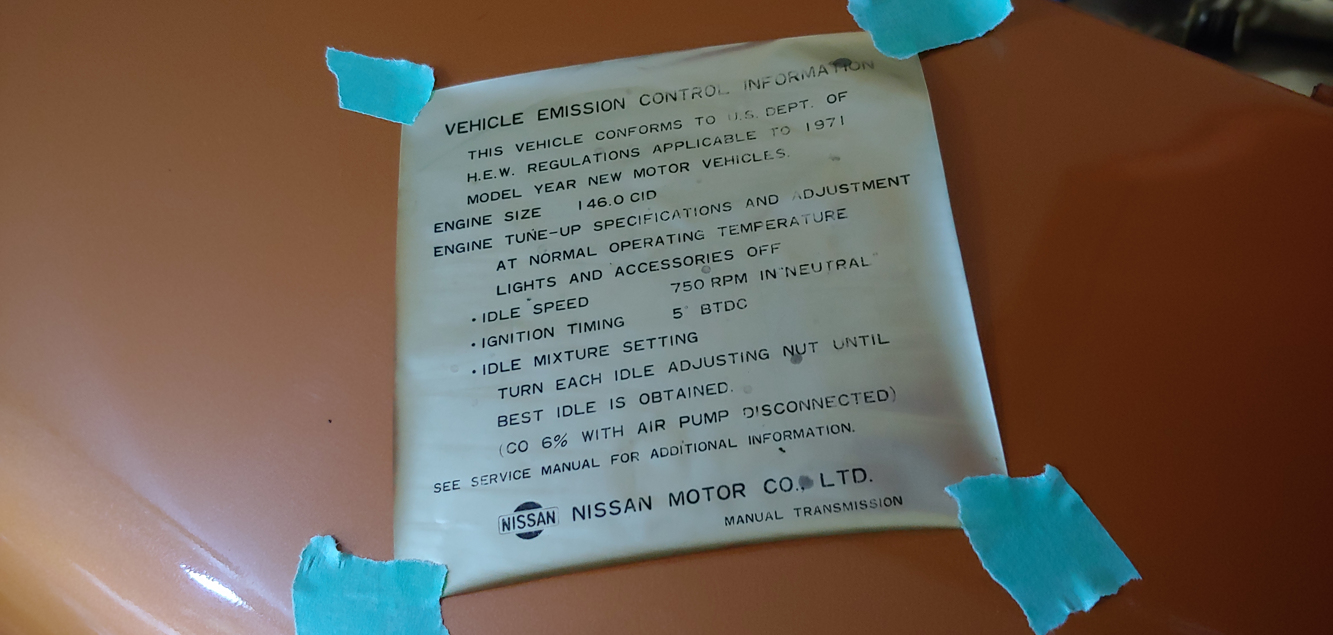
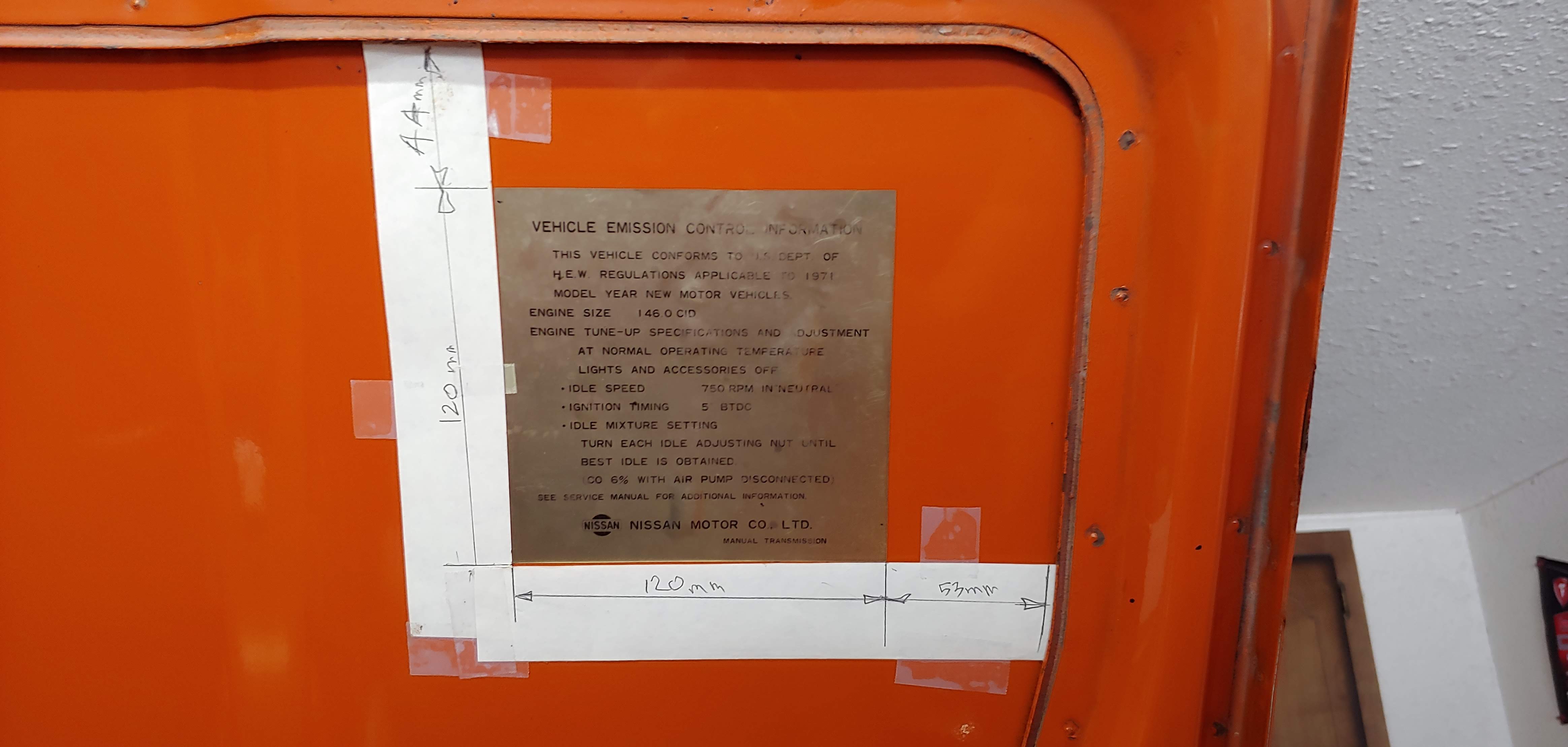
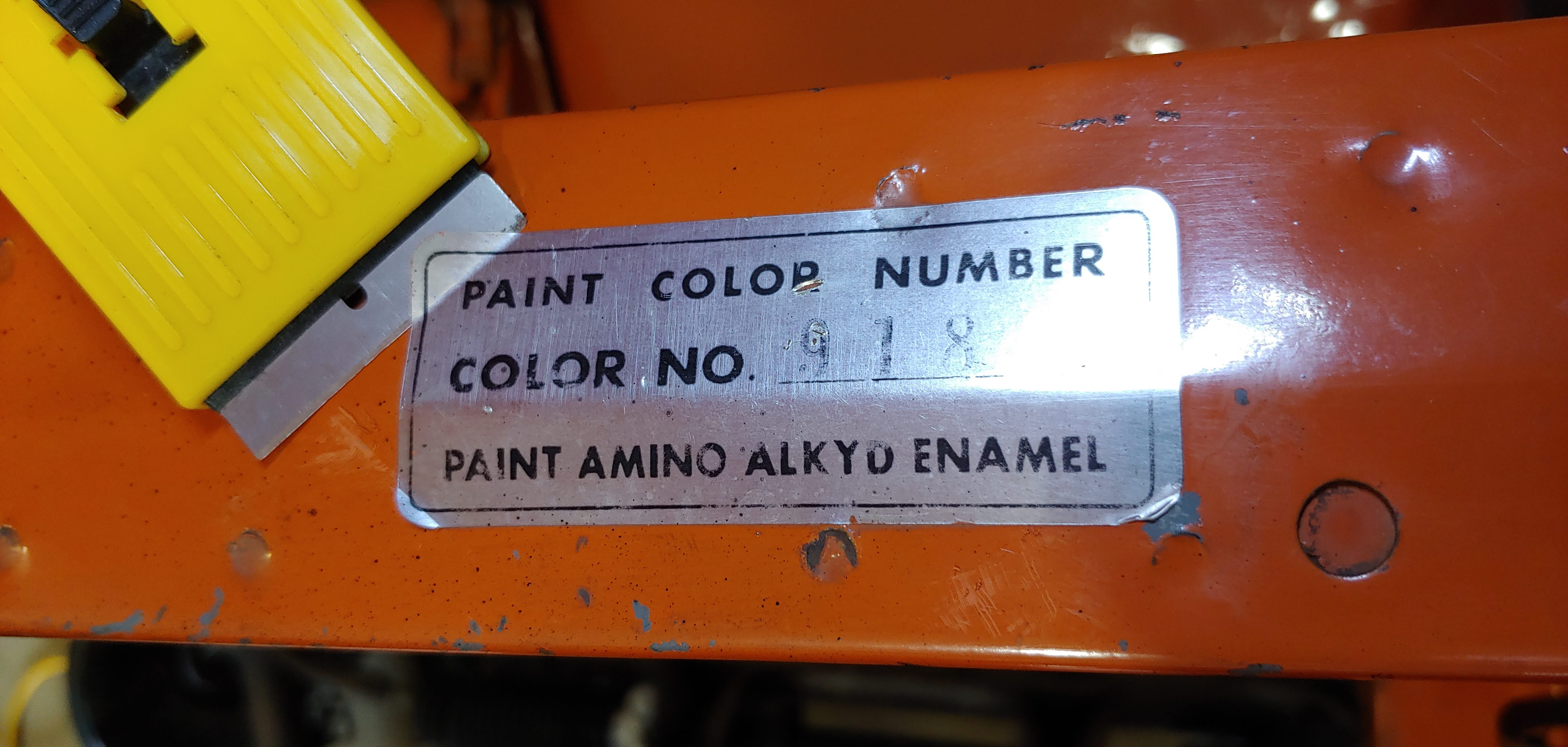
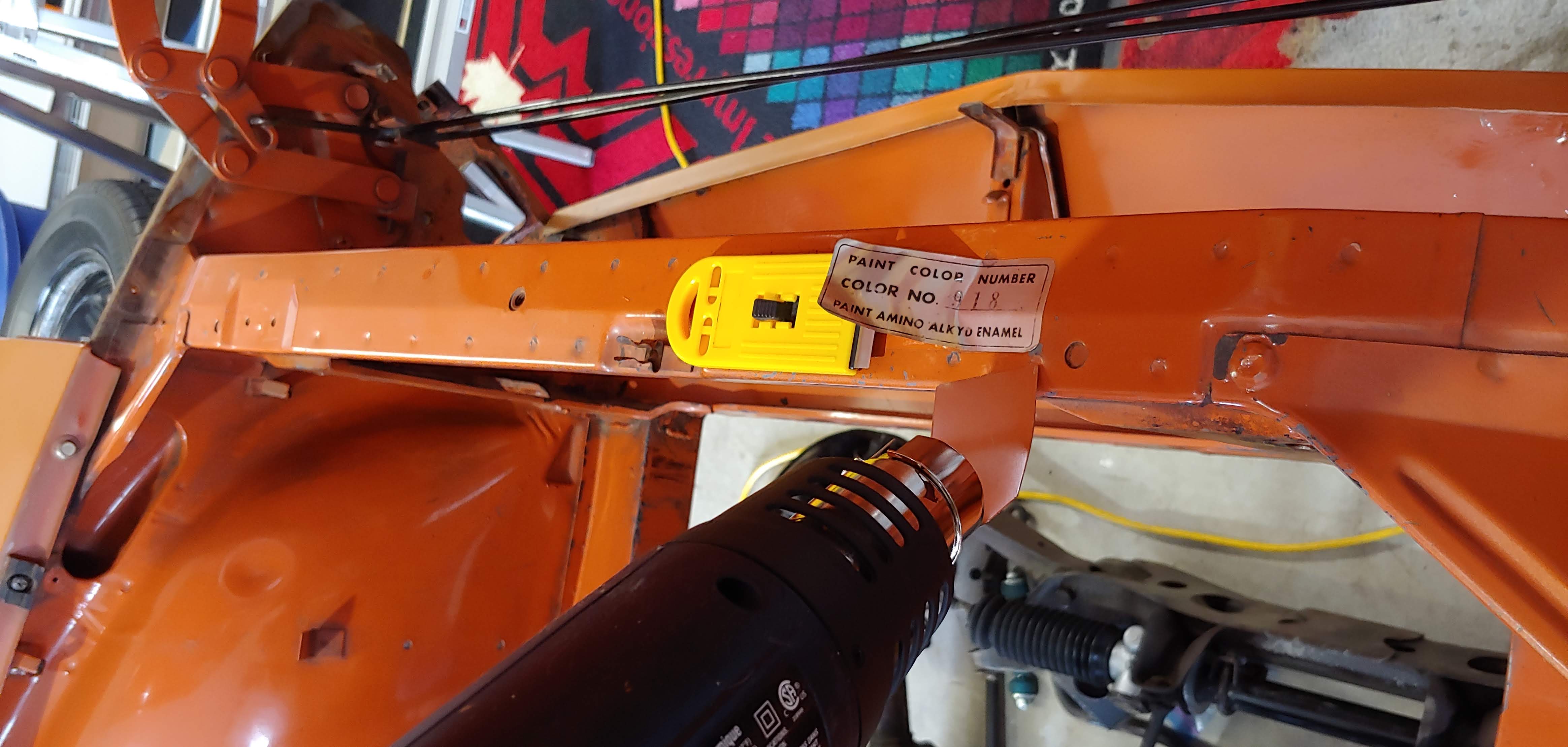
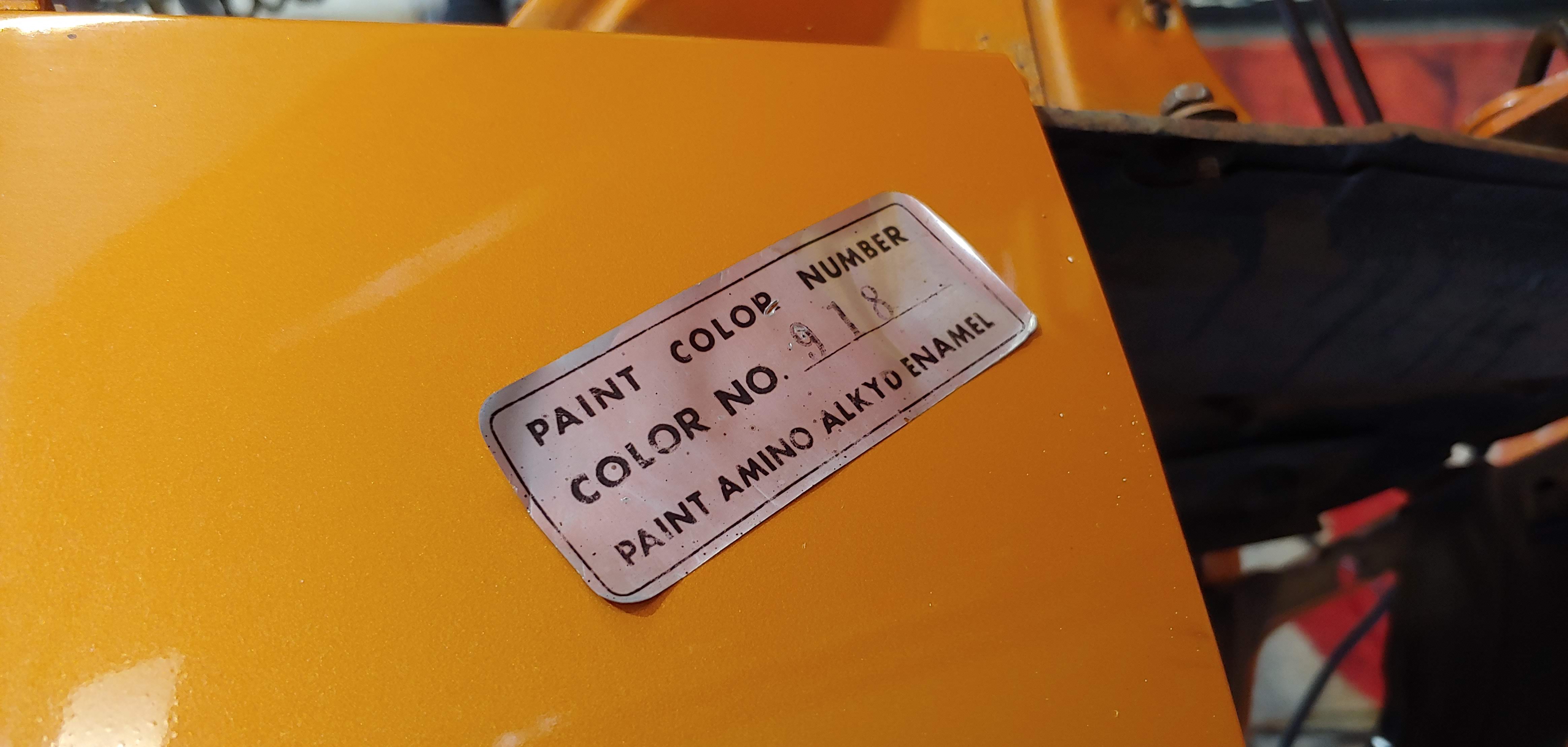
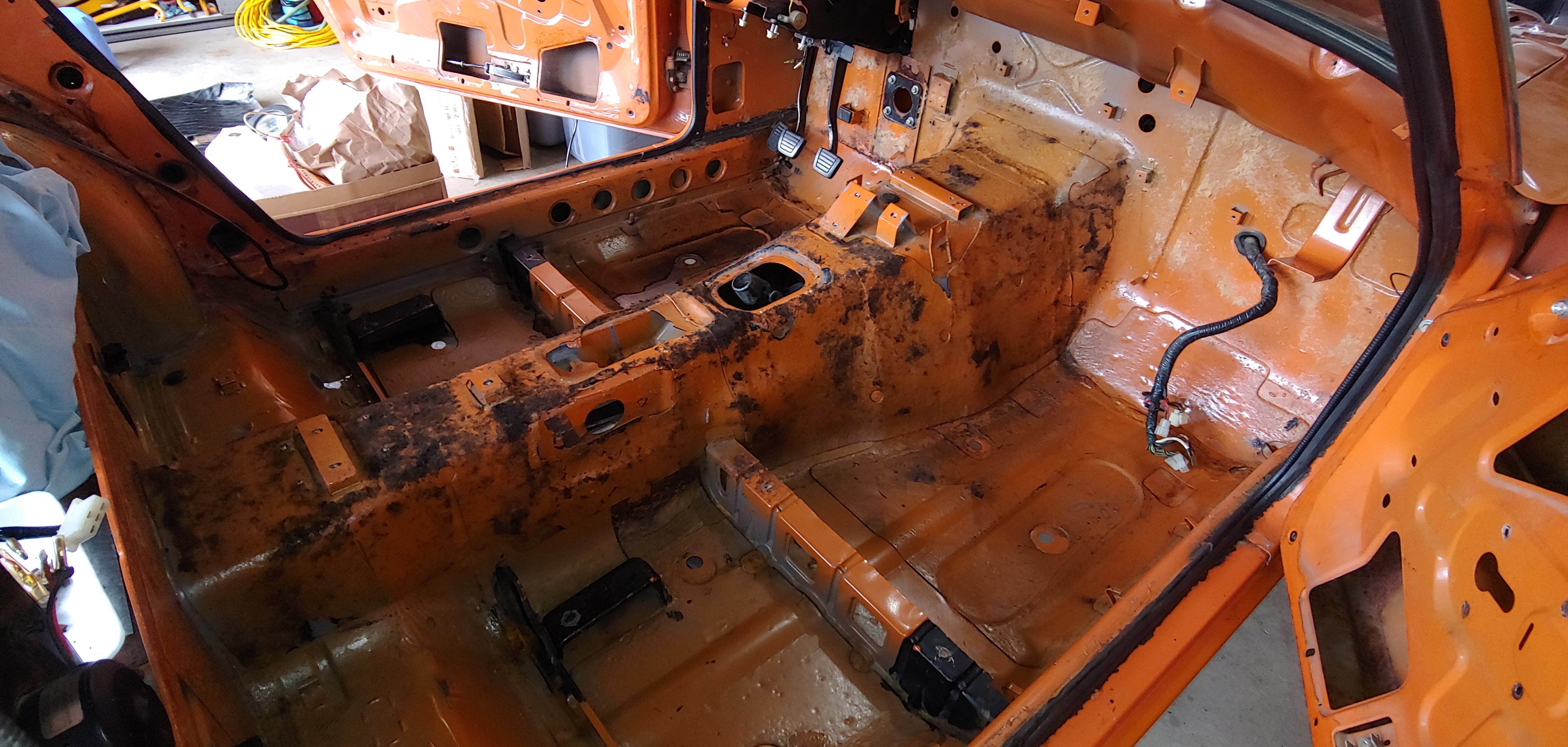
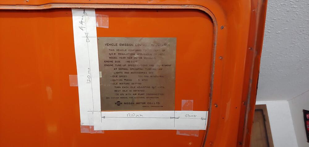
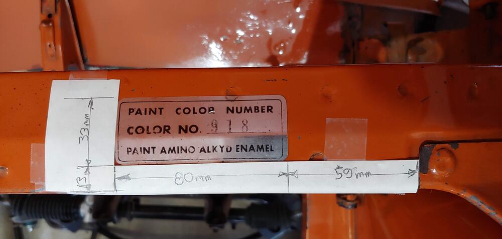
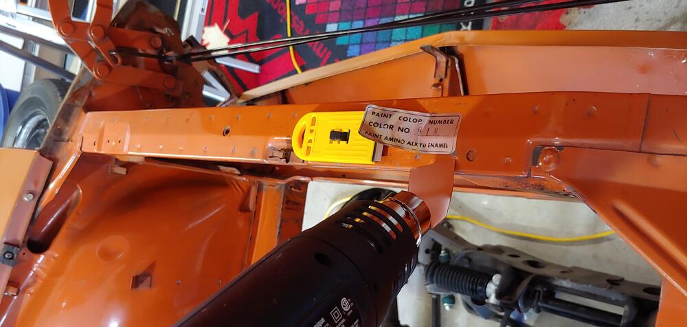
Today I started removing decals in the engine bay. The emissions decal under the hood and the paint code decal from the upper rad support. So far I have removed the paint code decal successfully in one piece. Has anyone reused these decals, I was surprised that this first one came off so good. Before I started I took a couple of pics to document the size and original position. To remove the paint code decal I used a razor blade and a heat gun (on low). First lightly heating the whole decal and then carefully using the razor blade to lift one corner. Then applied more heat and used the blade to continue lifting until I could hold the corner by hand to apply light tension and use the blade to aid in lifting. I stopped every few minutes to re heat and in about a half hour it was off. Hopefully the emissions decal will come off this nice as well. Even if I don't end up using them, they will be good for reference.

-
Nice work. Looks great.
-
Looks like I laughed to soon. Thanks for correcting us.
-
I had a laugh at that as well, was wondering if someone would mention it. You get the prize, Jim.
-
Here is what I found on a google search, seems to be a newer part number that supersedes the 18415-N3601 in the 1979 parts book https://parts.nissanusa.com/p/Datsun__/Knob-Choke/89430726/18415-N3500.html
-
I think Wally's car is a 1971 so he will be bending the tabs down and the nut will be correct. @Wallycan you confirm that.
-
That is interesting. Quite a few differences over the years. Easy to tell the bend direction by which side the nut is welded to.
-
Here's a couple of pics with measurements that might help, my grill is out.
-
Thanks, and glad to hear you might make use of the rear deck templates. I remember checking out the the work you did last year on tar mat replacement and it was the inspiration for creating my own templates.
-
-
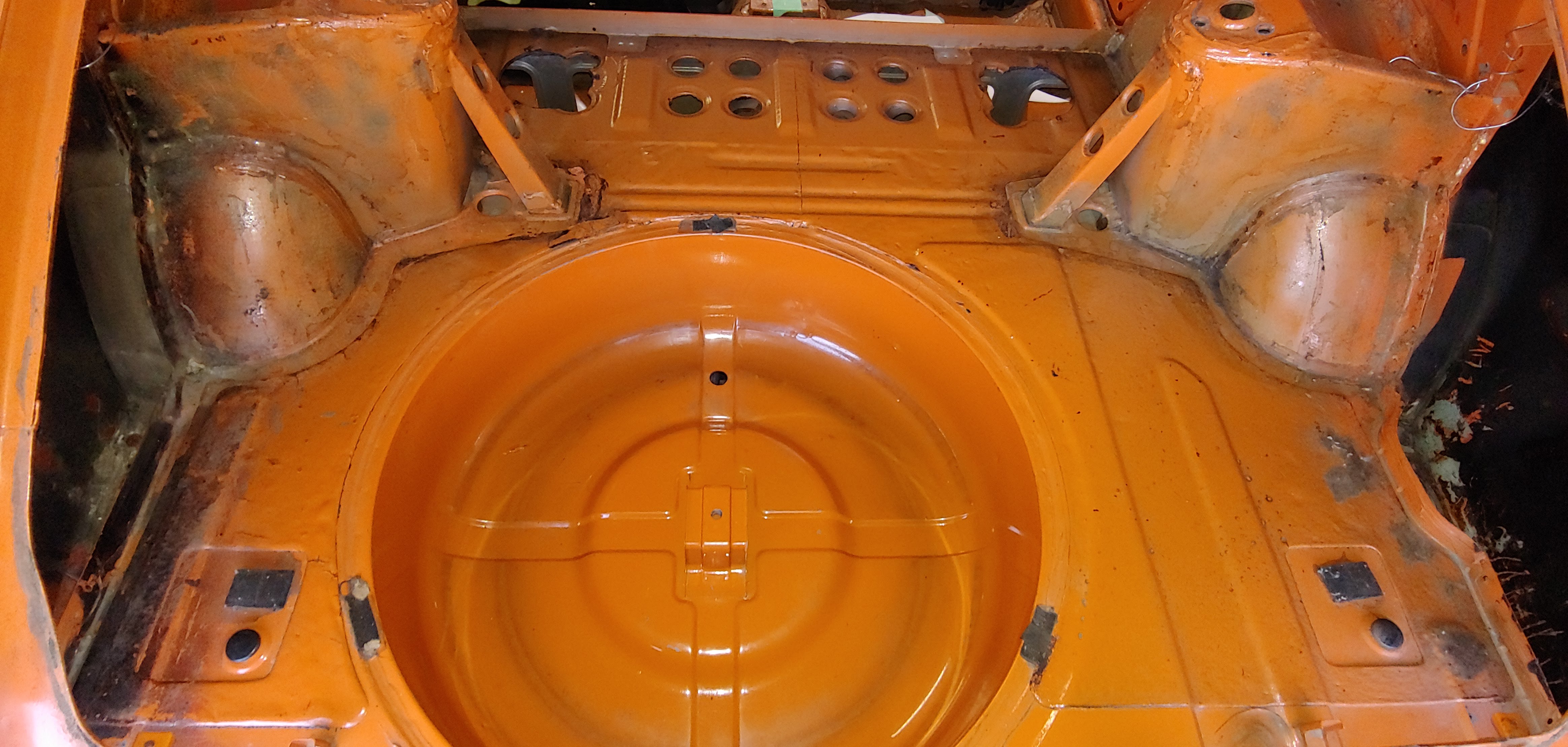
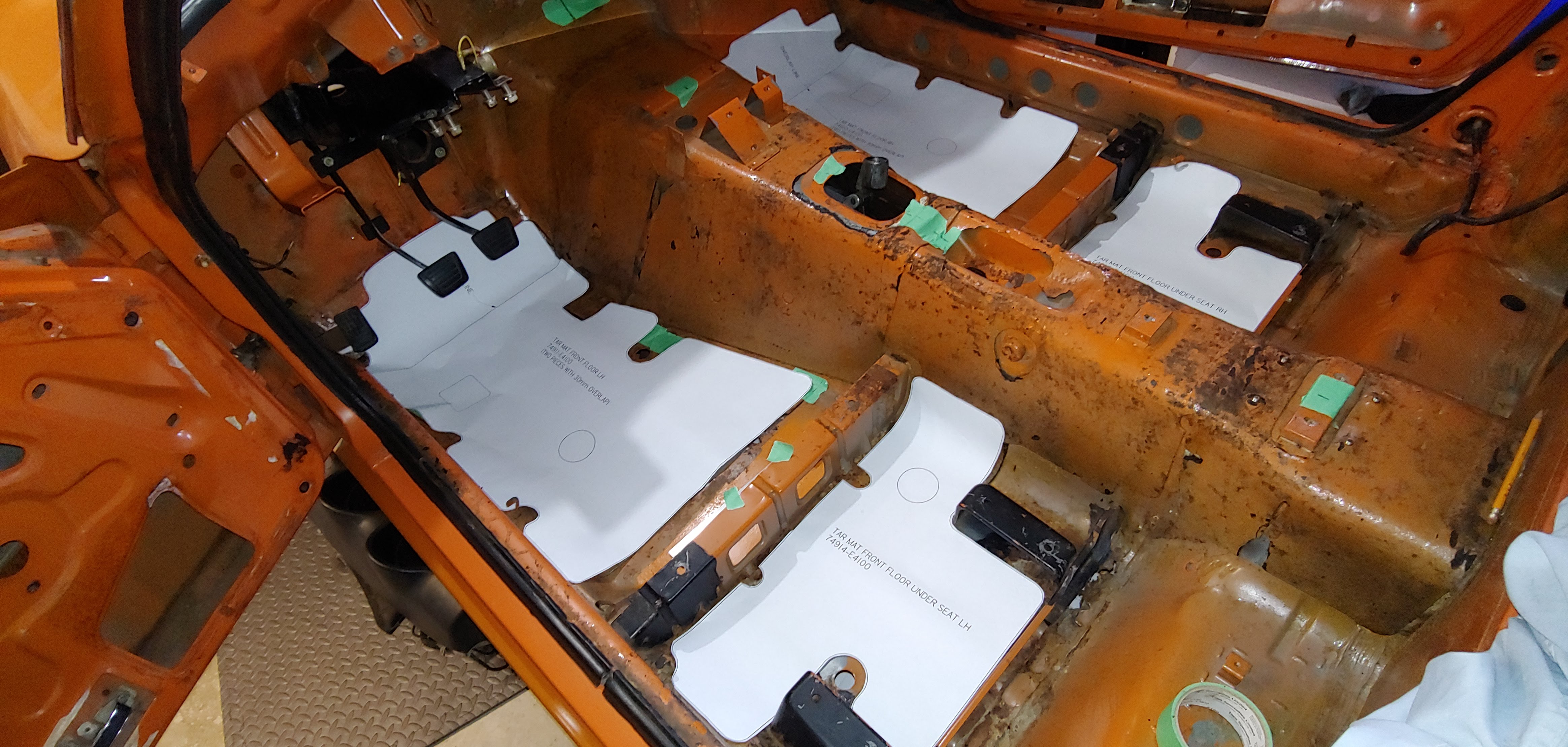
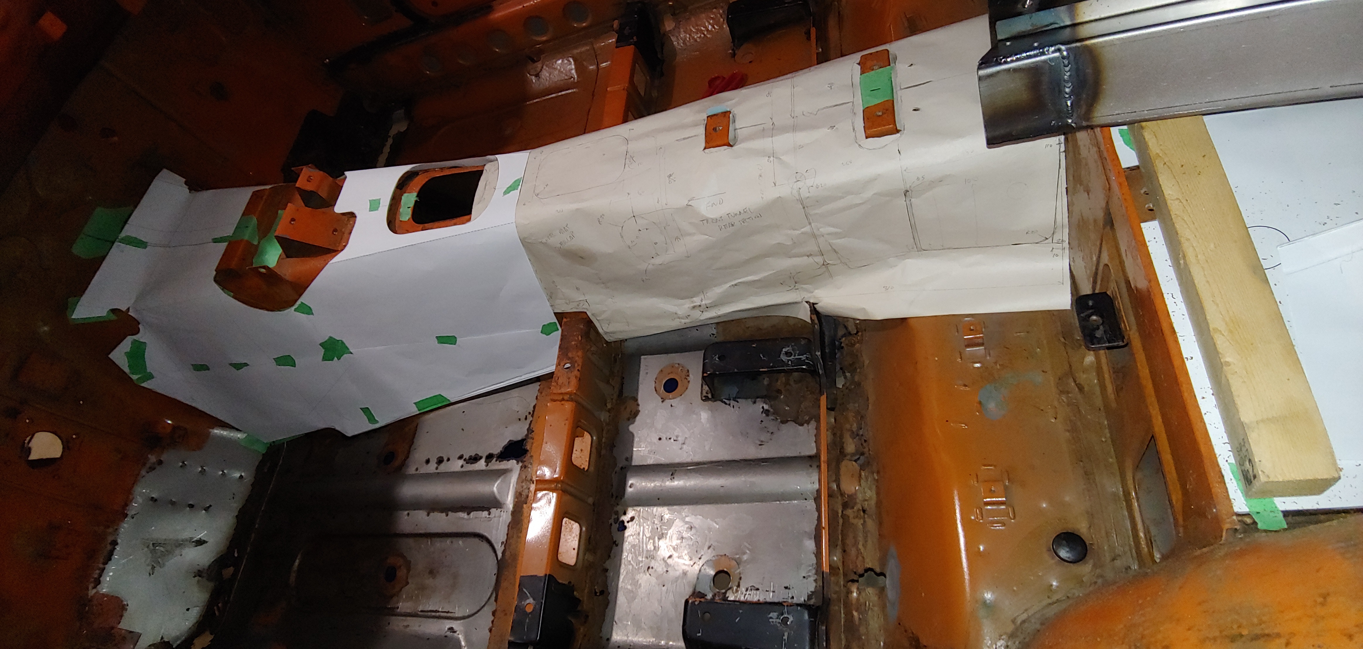
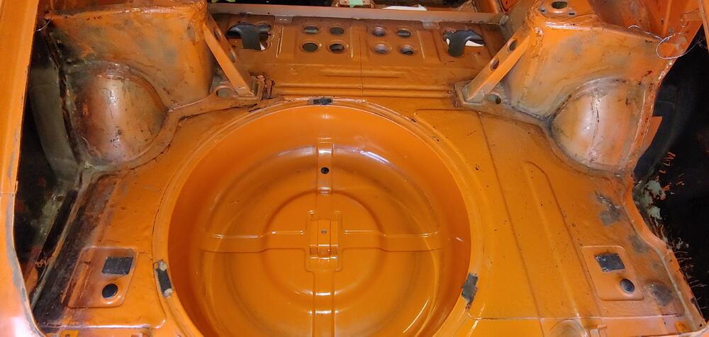
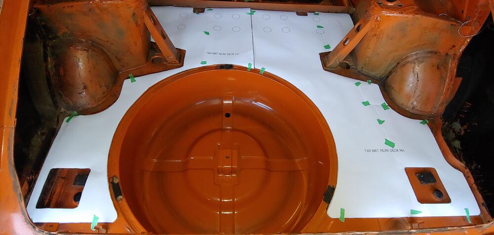
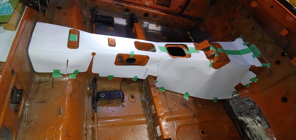
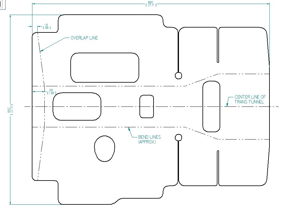
I have just completed creating templates in cad format of all of the tar mats in the interior of my 7'70 car, so that I can reproduce them later, after my floors have been repaired/replaced. I may not be removing all of my tar mats but I created the full set in case I need it. I have uploaded the last of these in .pdf and .dwg formats to our downloads in case they may be of use to others. Here is a link to the location: Here are a couple of pics showing the state of my tar mats before I started any removal, and a few pics from when I was doing the test fitting of the templates. I found that for the most part the thickness is approximately 2mm (0.08"). The front section of the transmission tunnel tar mat was a little thicker, more like 2.5+mm (0.10"). The transmission tunnel area was definitely the most challenging part of the job. On the templates I have added lines that show the approximate centers of the bends and also lines on the rear template to indicate how the front tar mat overlaps the rear. Here are examples of what the templates look like. If you use these I would recommend test fitting paper versions, before cutting any tar mat material. Cheers, Mike


-
How about the recommended re-torque after 100 miles?
-
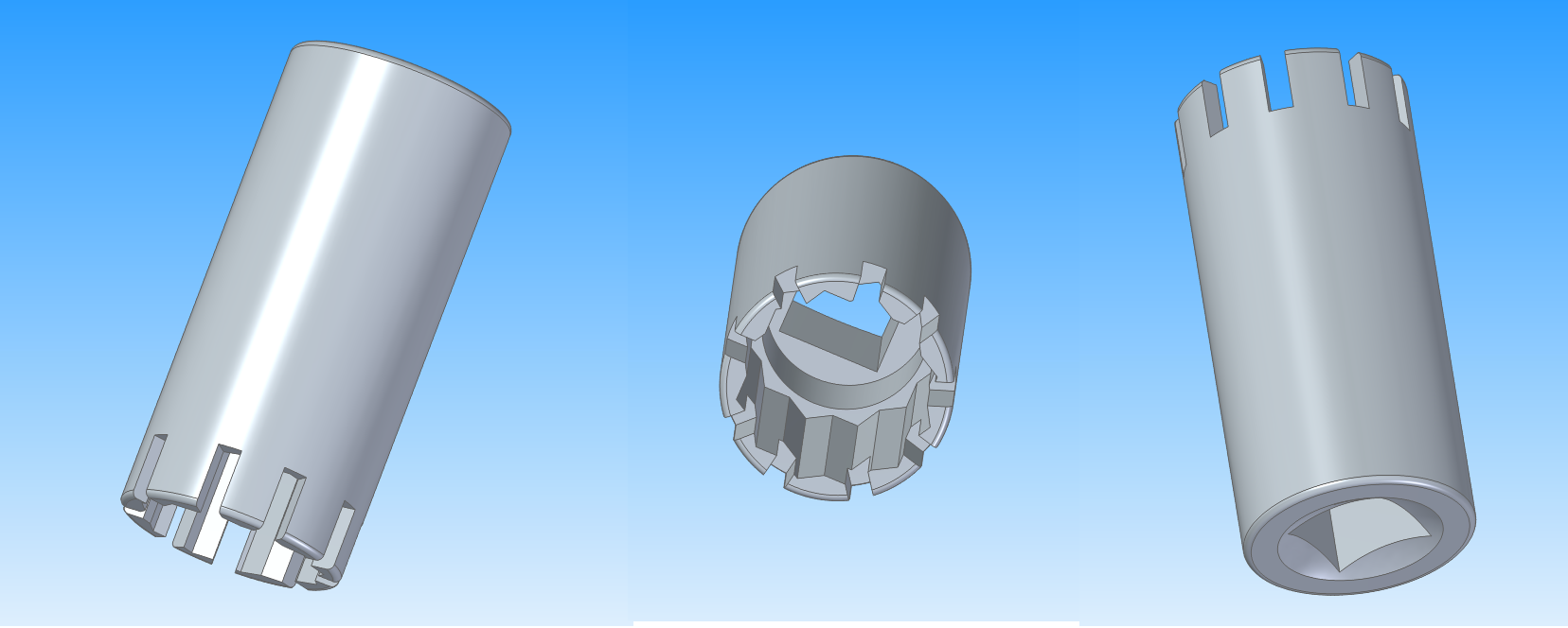
Definitely better to get the proper key. And a reminder that if you did go with the modifying a socket method, care must be taken to not apply excessive force or you could injure yourself if the socket exploded. Ie use safety glasses and gloves.
-
I made a crude model of the nut and put the modified socket on, hopefully this makes sense to you now.
-
If you are unsuccessful with Gorilla, you could take a 12 point socket that just slips over the un-splined part of the nut and mark where the splines are with a sharpie, or transfer with some plumbers putty. Then grind/file 9 slots to match the splines. Instant key. Of course the would be a once time use tool and care would need to be taken to not use excessive force.

-
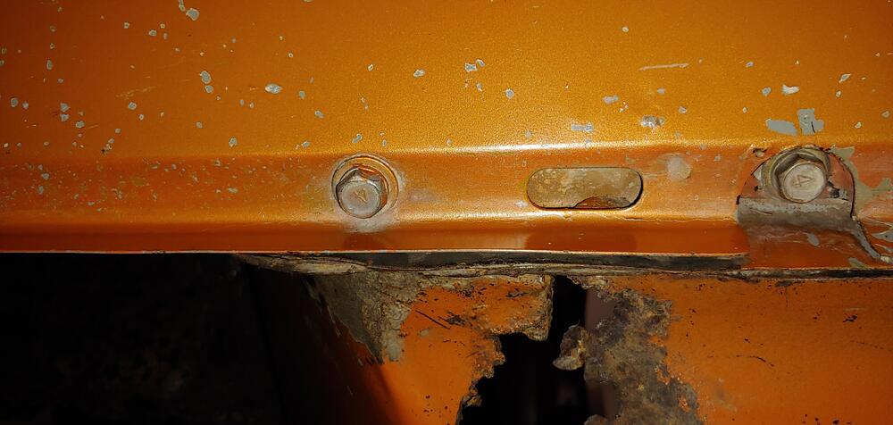
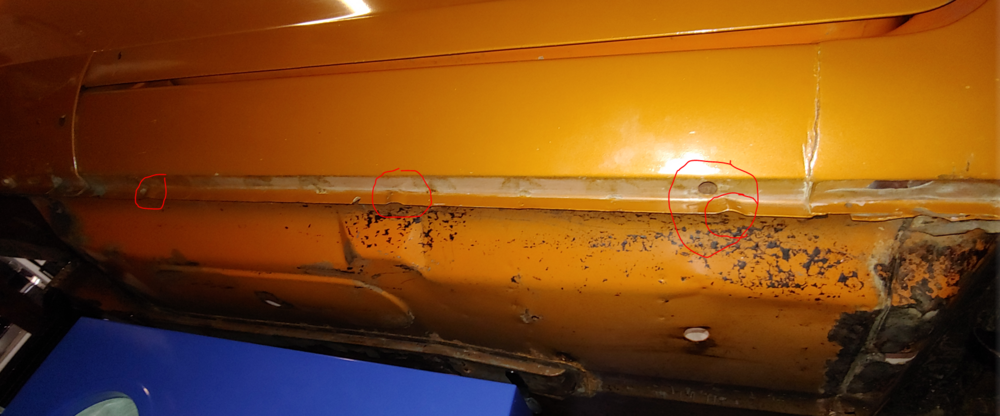
Cowl drain in lower front fenders, drains in rocker panels, one hole and three dimples. There are probably more.
-
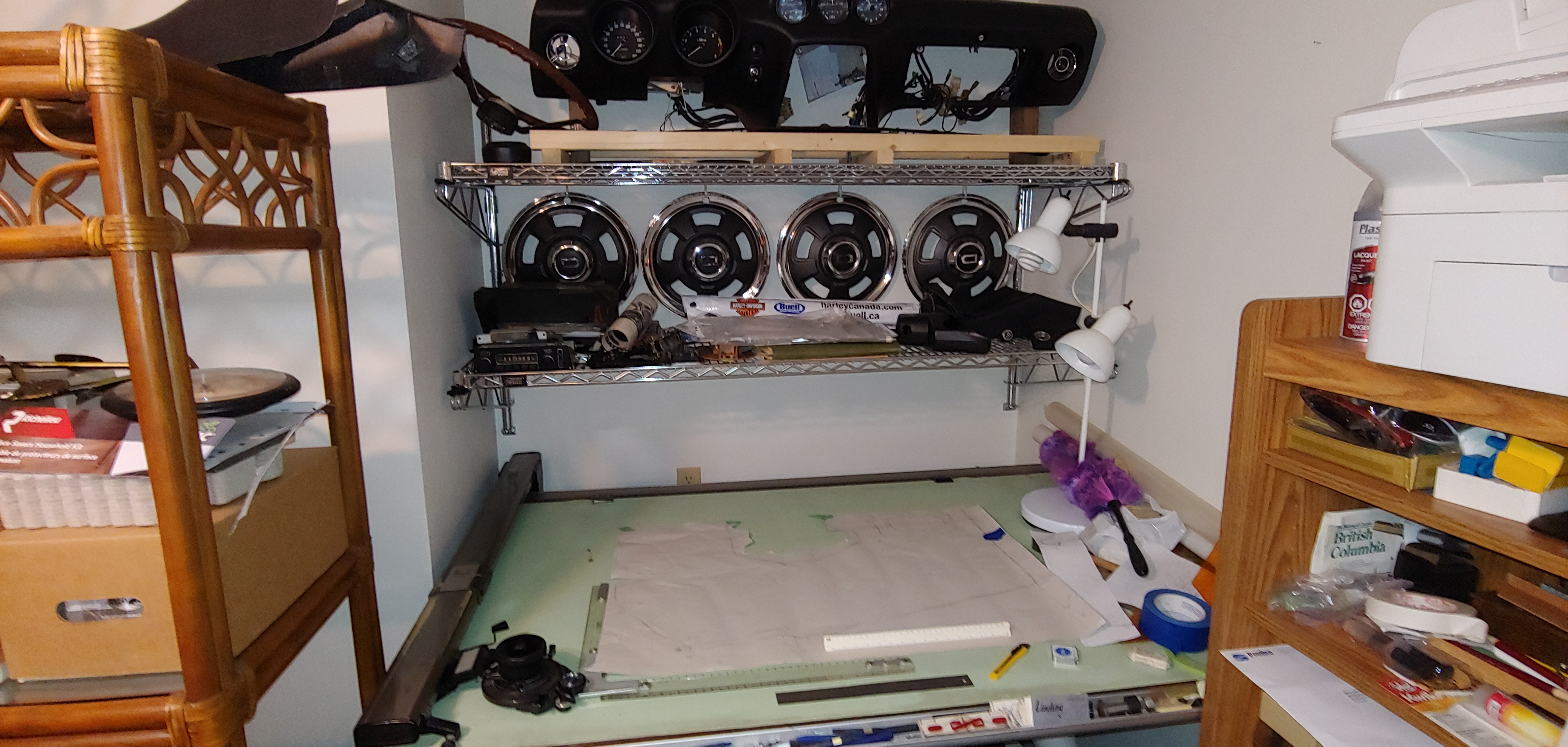
Spend much of the weekend continuing with my tar mat template project. Almost finished with the preliminary test fitting of the transmission tunnel templates. Hopefully just have to do one more round of adjustments to my cad file and then plot full size in one piece to do a final test fit. Actually two pieces, there is a front section and rear section that overlap. This has definitely proven to be the most time consuming part of the job. Luckily my drafting table and computer are in my office that is directly connected to the garage. As you can see I'm using all available space for parts.


-
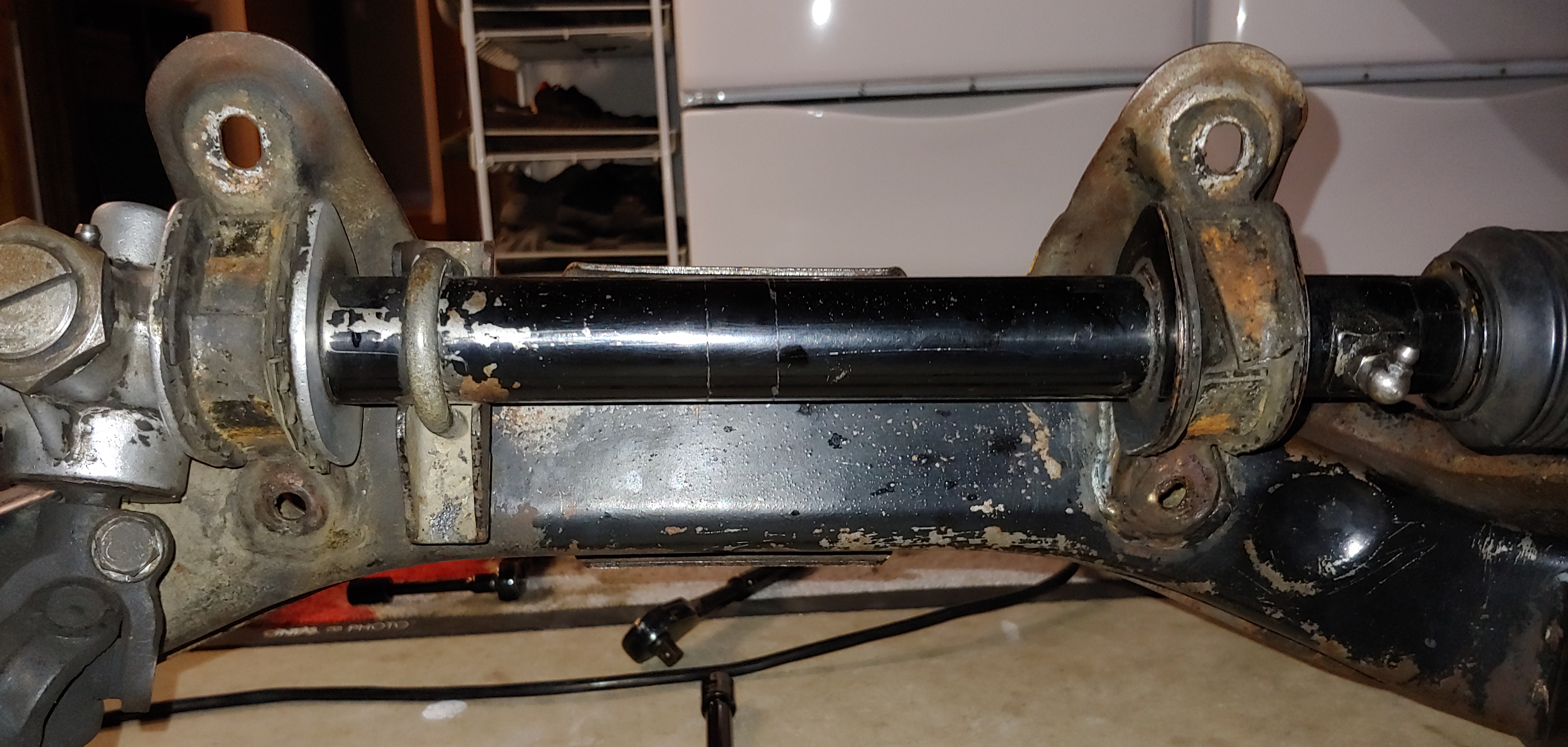
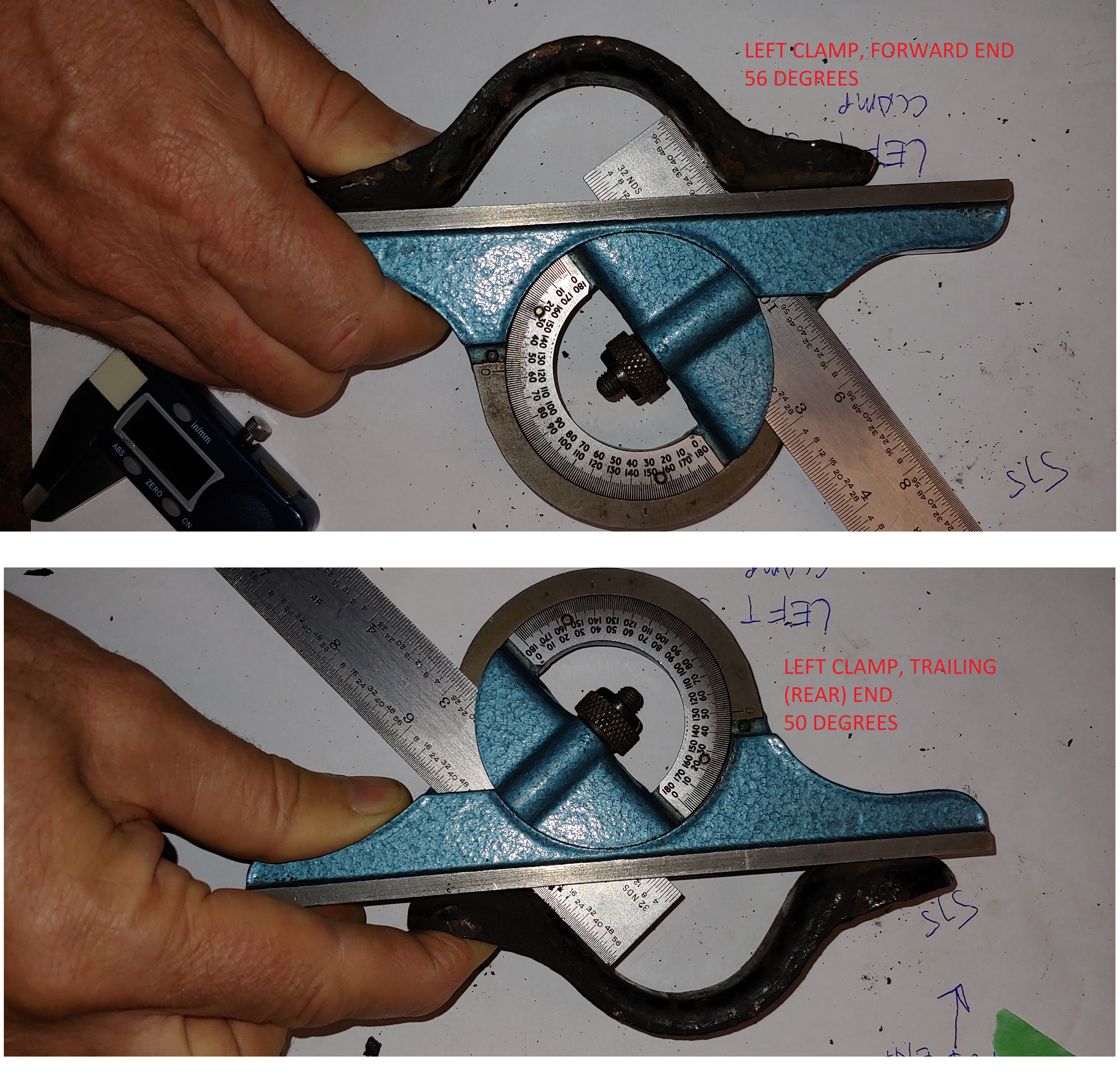
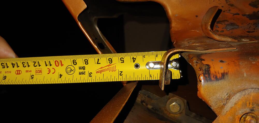
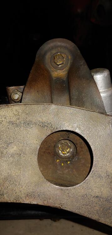
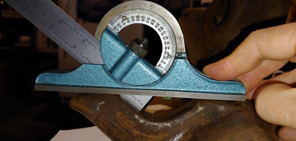
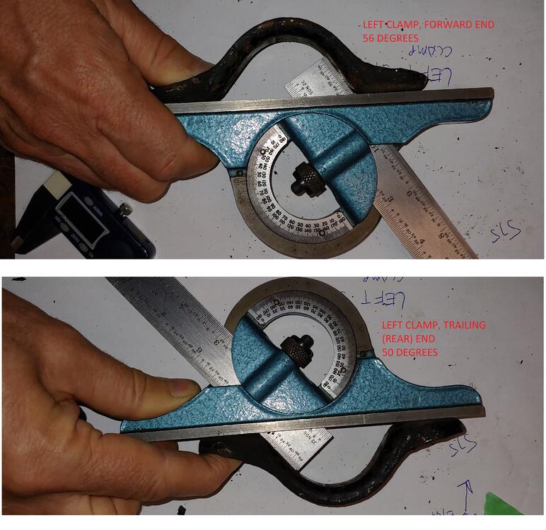
Yesterday I only removed the left clamp and it definitely had the 56° angle end at the front. In '05 I had a mechanic friend replace the rack boots while doing other service at his shop. I don't believe that he removed the complete rack. As of yesterday there were factory yellow paint marks showing. It still has the original bushings. I've owned the car for 43 years and this was the only work I've had done to the rack. However this morning I removed the the right side clamp and was surprised to find that it was installed opposite with the 50° angled end to the front, and 56° to the rear. Judging by the rust in the right clamp and twist of the bushing liner on the right side I think that it was backwards and the left was correct. Here is a picture showing both OE bushing on the rack with the clamps off, Regarding the angles on the crossmember, I have not removed the rack yet. But I have a crossmember from a 12/70 parts car and was able to check the angles on it. Both right and left are the same, the next picture is right side front angle that measure 38° The picture below is of the right side again, for the rear angle. The rear shape is different, it has angle change near the flat surface, I'm not sure how to describe that. The angle of the surface that is tangent to the curved clamping surface is approximately 32° Would probably need to measure the angles on the rack as well to review this in the context of an assembly to confirm which way is correct for the clamps.


-
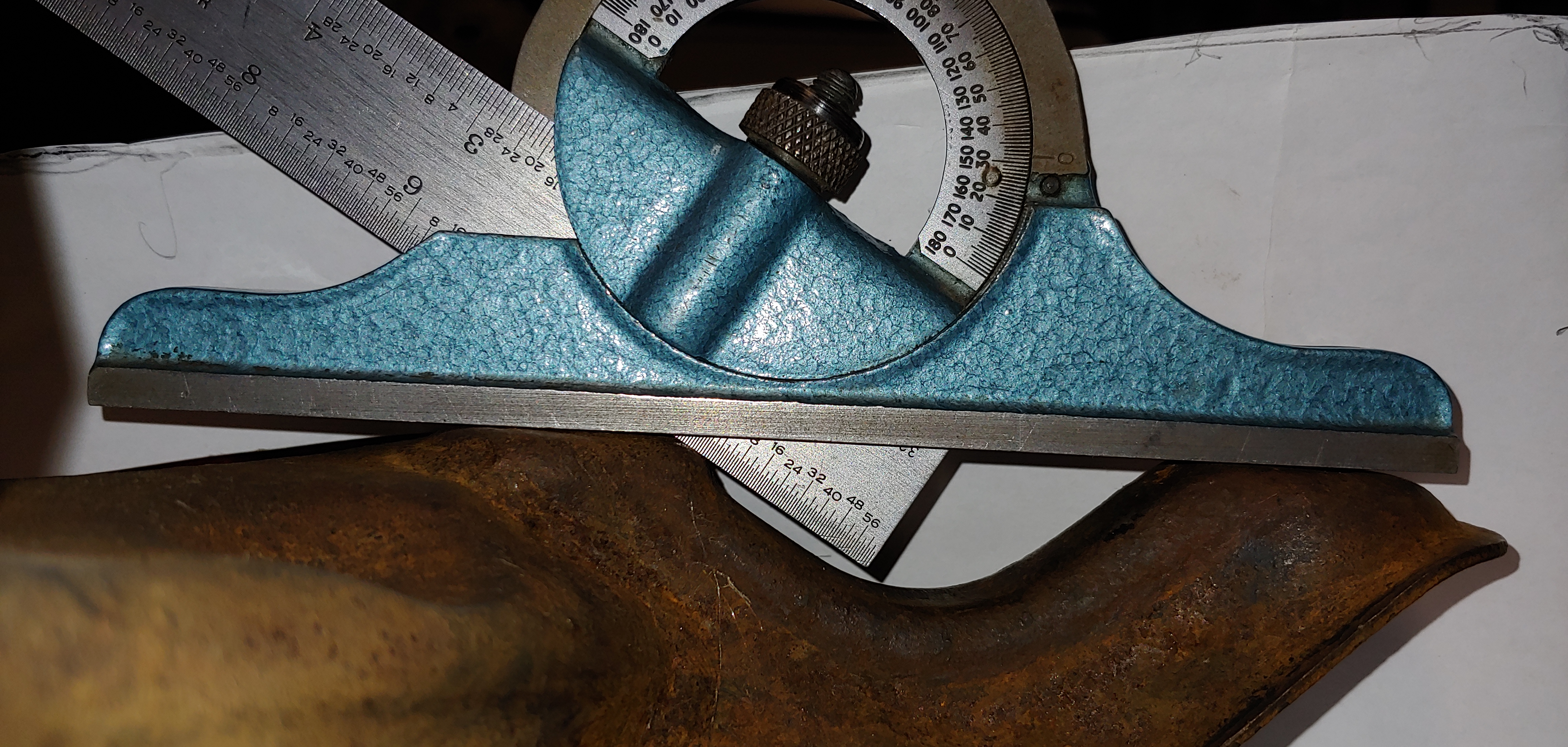
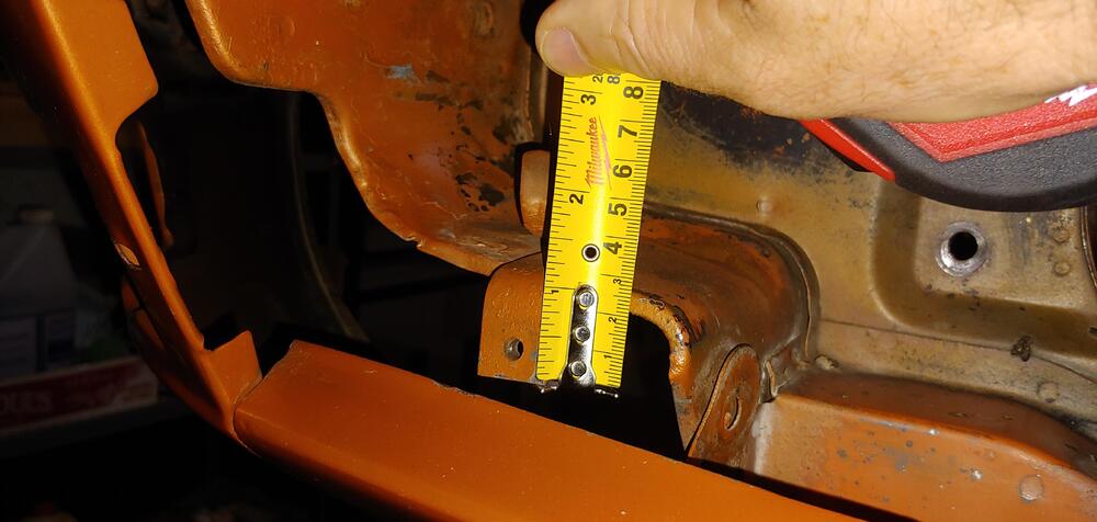
Interesting, Good eye @Captain Obvious. My front suspension is out so I thought I would check the clamps on my 7/70. I took the left clamp of and took measurements of the angle for the forward and rearward ends. The forward end measured 56 degrees and the rear measured 50 degrees, the bottom face was quite parallel for both ends. Thanks for posting this, I probably would have missed it. Good reference for when I go to reassemble at the end of my resto.
-
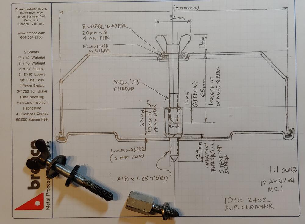
Here is a quick sketch of the air cleaner assembly on my 1970. Hopefully it might help with your search for hardware.
-
If I remember correctly you have to put the filter in to the cover with the winged screws and install them together.