Phred
Free Member
-
Joined
-
Last visited
Everything posted by Phred
-
 Stock head Thickness is 4.250 as I recall. It may be possible to find a place on the side of the head where you can measure it with some digital calipers. I havn't tried this though, I've always measured them on the bench. Phred
 -
Hey Carl, Talk about trivia!!! I have been fiddling with SU's since 1967 (on my first car, a Bugeye) and never new what SU referred to. Thanks, I hadn't learned anything today till I read your post. Good job. Phred
-
Hi Gary, Long time, no see. Don't lose any sleep over that crud. Sounds like you got rid of it. I've seen many engines like that. Which doesn't make it right, not uncommon though. A very small amount of oil which slips by the guide seals over time, mixed with a slight amount of fuel is the culprit. It starts growing when you shut off the motor, the back of the valve has this odd mix on it which starts to thicken when the motor cools down. Then the process starts all over again next time you run it. After a while it starts to build up, untill it looks like what you had. The reason its on the Intake valve, is the vacume present in the intake system behind the throttle plate. The seals are good enough to keep most of the oil in check, but not all of it. You won't see it on the exh. valves because the exh. pressure blows any deposits out or up the exh. guide. If theres enough oil present in the mixture, The back of the exh. valve will get a burnt brownish crud there too. Hang in there Gary. Phred
-
Most of the racers use flexible ducting called SCAT ducting hose. SCAT is designation for ducting hose with a certain specification. It is used in the aviation industry for routing air through the cowling for the intake system, and for heating/cooling entering the cockpit. It comes in sizes -2 thru -24, or 5/8 thru 6 inches. The most common use for racers is brake ducting, the stock car guys use it to route cooling air within the interior as well as intake cold air systems. Your engine likes to breath cold air, I did testing many years ago, on intake temp vs. horsepower. As I recall, there was a 1% increase in horsepower for each 7 to 10 degrees ( depending on air density and barometric pressure) of temp. change. Testing range was from ambient (68 to 72) to our particular under hood temp. of about 140 degrees. So you can lose or gain enough horsepower to make the investment worthwhile. Phred (ex. A & P mech. ex. racer, current race engine builder)
-
More on the order of 5 to 7%, and only if properly jetted on a dyno. Phred
-
I was asked again today what kind of assembly lube should be used when installing a new cam. So I thought I would pass this along since I see a lot of questions regarding cam installation. First, if its a new cam, always use the manufactures recomended lube. But if you have a cam, and have no lube, pick up a small can or tube of cam assembly lube from your local hotrod shop. This is usually a mixture of high pressure lube and Molybdenum Disulfide, or abbreveated as Mos2. Wipe this on the lobes and rocker contact pads. Use regular engine assembly lube, or engine oil on the journals. Additionally, a product marketed by GM called EOS (engine oil supplement) part# 1052367 should be added to the crankcase. Change oil after after no more than 500 mi. as this is strictly a break in additive. It is an excellent product I have used for over 25 years. Your local Chevy Parts dept. should have it on the shelf. And remember, new cam new rockers. If its a performance cam, check the contact pad wipe pattern, a tube of Prussian Blue marking compound (from NAPA) is helpfull here, and center it by adjusting lash pad thickness. Phred
-
Brand new, never mounted, Cannon Intake Manifold for sale. Designed for (3) DCOE weber's. Complete kit, (manifold and linkage) cost me $295.00. Will sell manifold only for $200.00 or, manifold with linkage for $250.00 or, manifold, linkage, and soft mounts, for $275.00 Freight Free!!! Phred Dial me direct @ fly.fred@verizon.net
-
Yes, you can do this yourself. I have swapped many cam tower sets onto other heads. Consider: the towers have a dowel around each bolt, the top of the head is flat (hopefully), so the towers shouldn't care what there bolted to. Do what Lance suggested, and be carefull to torque the bolts to 12 lbs. min., not to exceed 14 lbs. Also put a little engine oil on the threads, a bolt should never be torqued into aluminum with dry threads. Phred
-
Try: www.piercemanifolds.com
-
I raced various cars with SU's for years and never ran more than three pounds. Question for you guy's with the Z Therepy video, what pressure do they recomend? Phred
-
Ok, my belly's full and I can think again. I forgot to mention that when installing the seats in an alu. head to always use press lube, center point lube, or moly. They should also be installed flush with the combustion chamber. . Now, we have a head with new seats. Next is to cut/grind the proper three angles into one seat. (60,45,&30 degrees) I said one seat, not all of them. Install one valve, using only the inner spring, with retainer and locks, and lash pad. Now install the cam towers, and slip in the cam. Install the rocker and adjust the clr. (int.008 exh.010) Now wipe a thin layer of Prussan Blue marking compound (permatex,at NAPA) on the rocker contact pad. Turn the cam clockwise one revolution. Observe the wipped area, Center the contact patch on the rocker by, (a) Thicker or thinner lash pad. ( Grinding the end of the valve stem. © sinking the valve in its new seat, ( don't do this unless all else fails, we want to keep the head of the valve proud in the chamber) When satisfied with the valve height/contact patch of the rocker, then cut or grind, (depending on the equipment used) all the seats to the same height in the head. Make sure all valves are the same length. Presto! New seats/valves all set up properly. Now class, if you have been listening carefully, and still have questions, jot them down, and I'll get to them tomorrow night, after I have dinner with the Principal's new secretary. Professer Phred
-
Oh boy, what a wicked mess. First, find a new engine builder/machinist. This should be basic stuff for a qualified shop. Even without any specs this job can be accomplished. Let me explain, and take notes, there will be a test later. In my cyber shop I have a bare head, with cam towers. A cam, new valves, and as yet, no new seats. I also have my retainers, locks, and lash pads. First we need to remove the old seats. Tip #1, if the new valves are not larger in dia. than the old ones, theres no need to cut the head for larger dia. seats. If this is the case, then we will remove the old seats, and install new hard seats right in the old seat bores. If we can't find hard seats the right dia., Then the head will be cut to accept the new seats. Tip#2, only cut to the same depth as the old seats. Tip#3, removing old seats in an aluminum head is easy if you are skilled with a TIG (Heli-Arc) welder. Simply start your arc, and flow a puddle without adding filler, around the inside of the old valve seat. This will shrink the old seat And the heat from the process will transfer through to the aluminum, expanding the seat bore. Then the old seat falls or gets popped out with a couple of 90 degree scribe pics. Magic!. Step two. Install the new seats. An earlier post listed the press fit, but the factory specs are not right.(surprise) An alu. head should have .004 / .0045 press on the Intake, and .0045 / .005 on the Exhaust. (tech. note: the Exhaust will see a higher temp than the Int. and will expand the seat bore slightly more, so it gets a tighter press) Tip # 4, when installing the new seats, special alignment tooling for holding, and beating them in are required. Yes their actually beat in, not pressed. Tip #5, an hour befor you install the seats, put them in the freezer. That shrinks them a couple thou. If you really want to make them go in easy, Get the rose bud tip out and heat up the head to about 275/300 degrees, then they'll just about fall in. Ok time for dinner. Part 2 after desert. Phred
-
Kmack, Leaning the carbs more will not hurt the engine. It may hurt the throttle response on the bottom end though. What can hurt the engine is a lean condition on the top end, and it looks like your plenty rich up there. If you would like to do some testing, I have some SM needles I'm not using at the moment. If they work for you, buy some and then just send mine back. If they dont work, your not out anything. Contact me directly at: fly.fred@verizon.net
-
ScaryFast, If you bought both cam and rockers from MSA, you should have a good case for return/replacement. FWIW, I've also had 2 liter Ford CWC cams fail. They have a similar cam/rocker layout as Datsun. Phred
-
ScaryFast, I would be interested to know if the cam has a CWC embossed in the shaft between the lobes. I have seen a number of these cams loose lobes. From what I understand, the CWC is the company which produces the raw cam blank. I have seen different cam grinders use this cam blank with the same results. When I have a cam ground, I use an original Datsun cam as a core, and request the cam grinder to grind and return this particular cam, and not put it on the shelf as a core and return another non Datsun cam. I also use only OEM new rockers as I have wiped out lobes on the dyno using aftermarket rockers. As a non-scientific test I hardness tested both the lobes and the rockers. I found the hardness of the cam/rocker combinations varied considerably. The "bad" cam/rocker combo had hardness that was seperated by only a few points on the (standard)Rockwell C scale. But the Datsun cam/rocker combo had a greater difference in the hardness of the two pieces. It seems that if the two pieces are too similar in hardness, they "fight" each other, and gall. The dissimilar hardness of the Datsun parts seem to allow the two parts to work together without galling. I am a racing engine builder/machinist, not a metalergy expert. But this has been my experiance with wiped out lobes on Datsuns, and how I minimize the risk when building a new engine. Also, know you are not alone, many others have had this same problem. Good luck. Phred
-
First, be aware that there are two methods of measuring duration.The first is total duration, where the starting, or opening point on the degree wheel is the exact point the lobe departs from the base circle. Concluding when the lobe reenters the base circle. These points are very hard to note on a degree wheel. But these are much bigger numbers than the standard checking points (usually .050, but not always), so the manufactures always advertise these numbers. The real world duration numbers will be the duration at the "checking height", (.050, or whatever the manufacture designates). So when comparing duration numbers, make sure they were checked at the same height to make a valid comparison. For example: Electramotive used to sell the trickest cam for the L28 GT2 engines. This cam was designed for Titanium valves, and made power to 9000 RPM, and produce around 300 HP. I can verify this because I built and dyno'ed these engines. Typically, the specs, checked @ .050 were as follows: Int. open @ 25 btdc Exh. open 55 bbdc Int. close @ 55 abdc Exh. close 25 atdc Int. Dur. 260 degrees Exh. Dur. 260 degrees Lobe centers 105 degrees Lifts were kept down to about .590 for valve spring life, or for a one race shot like at the runoffs we could squeeze out another .025 lift by changing lifters and lash pads. FWIW Phred
-
Hope this works. There are some pics of last years show plus some info on this year. http://www.oregontrail.net/~rond/nwdoa.htm Phred
-
I think you'll be hard pressed to find one to rent, unless you know a tune up or A&P mechanic. These gauges can be damaged if handled improperly. There are two different types, a dual gauge, which is a bit more accurate and generally more expensive. And a single gauge type, these are usually less expensive, but do a very good job if you can supply a constant air supply to them. I've used both with excellent results. Moroso has a very good single gauge unit (part #89600). A call to your local hotrod shop should provide a price. Phred
-
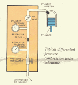
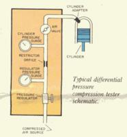
I have heard of some people hooking up a starter to an engine on a stand, and cranking to get a reading. But... A more proper test for compression is done with a gauge called a leak-down tester. Tune up shops and racers all use this as a diagnostic tool to clairify an engines condition. However, this devise will pinpoint where the leakage is, and tell you how much (in psi & percentage) leakage is escaping. A compression tester only tells you that a certain cyl. is 5 or 10 lbs. low. Is it a valve? gasket? rings? a crack? You won't know unless you use a leak-down test. I use these things on a weekly basis on stands and on the dyno, and I can tell you they are the way to go. All aircaft shops use these and have standard readings that will allow an engine to pass or be repaired. They sell for anywhere from $50.00 to $150.00. Basically they work by setting the piston at TDC on the compression stroke, and pumping and setting a regulated (80 or 100psi) amount of air into the cyl. There is a specially sized restrictor in the gauge which will allow the gauge to display the amount leakage taking place. So if the gauge is set at 100 psi, and then attatched to the cyl., and then the gauge reads 88psi, the engine has 12 percent leakage. Then you just use your ears to follow the sizzle. If an intake valve is leaking, you will hear it at the carb, If the rings are leaking you will hear it by listening at the oil filler cap, Head gasket leakage will show bubbling in the radiator. Fun huh. Hope this sheds some light on the subject. Phred
-
Use the following for your information, I'm not trying to sell anyone on JE Pistons. I Just had some custom flat top (with valve reliefs) pistons made by JE, and these are the costs: L-28 flat top custom specs.........$82.00 ea........Total$492.00 wire locks.......................................................................15.00 JE std. pins.....................................................................45.00 Ring set..........................................................................90.00 O-ring support................................................................22.50 Pin fitting........................................................................22.50 total$687.00 freight 12.66 ___________ Grand total $699.66 You know the old saying: Speed costs money, how fast do you want to go? I guess I want to go real fast. Phred
-
In reply to an inquiry on the compression ratio of an L28 with dished pistons, N-42, .060 surface, etc. I was troubled with not being able to reply with any accuracy. I work daily, machining, adjusting, and setting up compression in racing engines, and this was my response. Hopefully, it might shed some light on a problem encountered at some time by most Z rebuilders. Ed, You have too many unknowns in your engine to nail down a C.R. within half a point. For starters, how many cc's are contained within the dish of the piston? More important is the combustion chamber. If it was brand new, you could go with factory cc info, but a used head may have had a valve job or two, slightly sinking the valves (adding cc's). Or it may have already been surfaced, (removing cc's) if so how much? Which head gasket will be used? Different gaskets contain different amounts of area (cc's). The following will explain how to compute your true compression ratio. To do this everything needs to measured in cc's, (cubic centimeters). Once you know what cc's your working with, a simple math formula will give you the bottom line, without question. There are a few special items you will need to beg, borrow, or buy. The first is a cc burette. This is a glass or plastic tube graduated in cc's. They are commonly found with a 50 or 100 cc capacity. (100 prefered). The next is a cover plate. These can be bought (Moroso) or made yourself. The plate is commonly a 6"x6" square piece of plexiglass 1/2" min. thickness with a 1/4" chamfered hole in the middle. Last, a pocket calculator. The object of this adventure is to determin these unknowns: 1) Actual displacement of one cylinder. 2) Displacement of the cyl. gasket 3) Displacement of area above piston @ TDC (dome is negative, dish is positive number) 4) displacement of combustion chamber 5) total displacement in cc's above the piston @ TDC (found by adding and or subtracting the above figures) The following example is a 240 engine I built for SCCA ITS Stroke: 2.902 Displacement: 2454.5cc's (formula: bore x bore x 16.387 x .7854 x stroke x # of cyl.) (16.387=cc's per cubic inch) (.7854= area of a 1" circle) Displacement of head gasket: 6.9cc's (3.375x3.375x16.387x.7854x.047 - same formula as above) (3.375= inside dia. of head gasket) (.047 = compressed thickness of gasket) Displacement of area above piston @ TDC: .52 cc `Displacement of combustion chamber: 41.4 cc's (determined by use of cc burette and plate, valves and spark plug sealed with light grease) Total disp. in cc's above piston @ TDC: 48.82 basically- 6.9cc head gasket .52cc block volume 41.4cc combustion chamber ------------ 48.82 cc total volume Now that simple formula using total volume and displacement: 409.08 (displacement of one cyl.) ---------- 48.82 (Tot. volume) + 1 = compression ratio basically: 409.08 divided by 48.82 = 8.38:1 + 1 = 9.38:1 C.R. Thats it! If I didn't screw up my math. Kind of looks complicated, but once you do it a few times its a snap. This is worth more than 2 cents, so I'll call it my nickels worth. Phred Gresham, Or.
-
Please do us all a favor and post the name of the transport Co. so nobody else gets burned. Phred
-
2ManyZs, I Agree. Part of my job as a vintage racing engine builder, is balancing. I just figured this up in my noggin, but I think Im close. His difference is only .2 oz. One oz. is 28 grams. So .2 oz. is about 5.5 grams. Race engines require a tolerance of plus or minus .5 grams for each component. So for a streeter, thats only plus or minus 2.75 grams. Actually thats darn good. FWIW. Phred
-
Zvoiture: Now I really believe I belong here. I was an outcast. A non-believer. I was, dare I say it? un-American. I didn't like football. But I survived. I believed in...Racing and ...Z-cars!! Thanks I needed that. Phred
-
Just a small correction on Brian's N-42 head. The valve guides are a cast iron alloy, which is what Datsun supplies with those heads. The seats are hard steel, not the Bronze alloy of earlier heads. What I don't know is when, and on what head # they started using hard seats. Phred