Phred
Community Member
-
Joined
-
Last visited
Everything posted by Phred
-
Loren, You sure get the prize for cam grief! I have to ask though, What company? Phred
-
Marc, I cut high perf. seats on a daily basis. There is literally a catalog of available seat designs, angles, and widths. Generally speaking, a three angle seat has a 45 degree contact area, with a 30 degree angle on top, and a 60 degree angle on the bottom. Note: air flowing across a surface will "separate" if forced to change directions more than 15 degrees, causing turbulance, or loss of flow. That is why a three angle valve job increases air flow. The other general air flow trick is to grind a small 30 degree angle on the inside of the 45degree angle of the intake valve. Again, to help smooth air flow across the back of the valve. All this results in what the tech. people call volumetric efficiency. So you get more horsepower out of what you already have. Seat widths vary depending on application, valve material, and length of required service life. Example: a race engine with steel valves can use a 1mm wide intake seat, and a 1.5mm exh. seat. A high perf. street car would have a longer life expectancy with a 1.5mm int. and a 2mm exh. seat, with only a small reduction in flow. Seats also have another function. Heat transfer. For this reason, turbocharged engines will frequently have a wider exhaust seat, (3mm or more) All this is a general overview to show how valves and seats should be designed around your specific engine. Phred
-
Walter, There are probably a dozen ISO standards listing what MAY be an acceptable imbalance. In the real world it works like this. Basically, an electronic, dynamic balancer detects an imbalance in a rotating mass (crank, damper, fly,clutch) by the use of load cells under a support beam/roller. The imbalance, measured in grams, ounces, or whatever, is determined from its location from the center of the axis. Through the use of an indicating strobe, or CRT display, the location is pinpointed. Weight is removed (or added) to eliminate the imbalance. In the racing industry, there is really not an acceptable imbalance. We just work at it till the dials on the gauges don't pick up any more imbalance. ( as close to zero as possible) BTW, you live in the center of the racing world. There are probably more racing engine shops per capita there than any where else in the world. Let your fingers do the walking! Phred
-
Walter, The most common, (and easy) way to see if your fly needs resurfacing, is a straight edge check. Take a 12 inch rule (like from a combination square) or just a good carpenters square, and set it on edge on the disc face of the flywheel. Then use your feeler gauges to check how much wear has taken place on the disc area. Also note if there is uneven wear from the inside to the outside of the disc area. There is no magic number here, but I resurface if I see more than four or five thousands. If you have wear or an uneven surface, sure you can bolt on a new clutch. But you will have accelerated disc wear and possibly chatter till the new disc conforms to the old uneven surface. I have balanced literally hundreds of flywheels and clutches on a Stewart and Warner electronic balancer. I would guess that 1 in 15 new clutches would be "balanced" out of the box. Also, the procedure for balancing a fly/clutch set is to first balance the flywheel. Then bolt on the clutch and balance again, by adjusting, or drilling on the clutch itself. Then you can change clutches without disturbing the fly balance. Additionally, a flywheel/clutch can be unbalanced to the point that it can hammer out the bearings, or spit a damper off, and you still may not feel the imbalance in the seat of your pants. Its your dollar, you be the judge. Respectfully, Phred
-
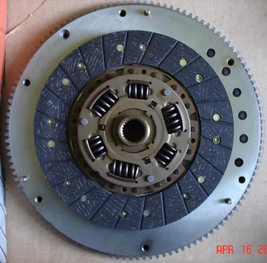
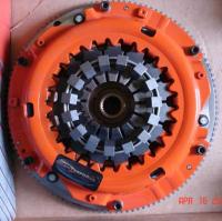
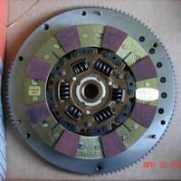
Walter, For reference, here are pics of a new Centerforce II pressure plate & disc. Its very obvious if you have a CF II disc, as there is a different type of friction surface on each side. If not, someone may have put in a CF I disc with a CF II pressure plate. I've never done this, but I don't know why it would not work. Its very common to destroy the dowels when removing them, to surface the flywheel. Just be sure to order some new ones from Nissan. Always use dowels in the flywheel. As long as you're doing all this, it would be a good idea to have the fly & pressure plate balanced as a unit. Its easy to get a weight imbalance when mixing & matching flys and clutches. Phred

-
I have a set of flat tops on rods, taken out of an 80' F54. Very good cond. They should have new rings and bearings installed before assembling into an engine. If interested, PM me with how many gold bars you can part with. Phred
-
Someone told me when you find an age you like, stick with it! So this year I'm working on my 16th anniversary of my 39th Birthday. Sorry I've not stayed in touch Gary. I have given up my business. As they say, I got an offer I couldn't refuse. I'm setting up an engine machine shop for a Porsche performance shop in Tualitin. We should be up and running in about three months or so. Till then, long hours and a long commute. I'll try and check in now and then. Cheers! Phred
-
It would be fun to meet the local Z people. But I will be on the road for three weeks, leaving 11-15-05. I'm a USAC Midget engine builder and crew chief. Our last race is in Orlando, Fl. on 12-02-05. Back in the world around 12-7. I have a bit of Datsun race engine experience to share with anyone interested. Be sure to post if you all get together at a later date. Phred
-
A complete L-28, unknown type is listed at 440 lbs. A 5- speed box at 90 lbs. Phred
-
Ray, Bang for your buck? All depends on how much buck. I installed a BAE kit for a customer in the early 80's. It wasn't difficult, and worked great. The only additional item I installed was an EGT gauge for induction tuning, and peace of mind. Stock Datsun pistons are cast and will not last for any length of time if any detonation, or excessive combustion temp. are encountered. So if the price is right, yes, good band for the buck. Phred
-
Clairify your float setting. If you are measuring the float level with the float lid upside down and measuring the gap between the float and the lid, your float level is too high. The stumbling you refer to is a classic high float level symptom. The high fuel level in the float bowl will slosh over into the jet well in right turns, flooding the air corrector jet. This causes a temporary stumble created by a rich mixture. You should be able to get all the HP you are capable of producing with 3 1/5 psi provided your pump has enough volume. Pressure over 5 psi will start to blow the needle off the seat and cause a rich unstable condition. Phred
-
Man, you've got one of the best tracks in the USA in your own backyard. Road Atlanta in Gainsville. Call them up, get a track schedule, and make some calls to the organizations that run there. Hope you get to run there. I towed 3000 miles to race there. Fast track, good fun! Phred
-
Carl took the words right out of my mouth. I'm sure most of us speak from experience. As soon as the car is completed, you can sell it for about 2/3 of what you have invested. I have built a couple cars from the ground up, the first because I thought I could save money, and I did. But its a major job. I also had all the equipment and ability to do the job right. I have also bought a used race car, (formula ford) and again Carl hit the nail on the head. You don't just jump in and go. You disassemble, recondition if needed, and reassemble. This gets you aquainted with all the parts, gives you confidence, and later at the track, if something goes wrong, you'll have a working knowledge of what the problem is and how to fix it. And you will have saved yourself a lot of money by buying instead of building. HOWEVER, there are some of us who actually enjoy spending hard earned money, inflicting pain, and doing things ourselves because we think we can do it better than the other guy. We're builders. We're the kind of people who would build an airplane rather than buy one. Even if we had the money to buy one. So if you're one of the latter, go for the gusto. Just be sure you have the ability, or desire to aquire the knowledge and ability, the equipment, and the space for an extended project. First, go to races, ask questions. Become informed before you start parting with all those greenbacks. Remember, Nothing happens overnight. Well... except for that girl I met in San Francisco back in 1969, but that's another story. Good luck. Phred
-
Ok, I'll toss some fuel on the fire. The oldest engine I have built was a 1927 Wright nine cly. radial aircraft engine. It was the same type (not the same one) that Lindberg flew across the Atlantic. It, like all radial aircraft engines has a OHV layout. These engines have a big (over a foot in dia.) flat cam disc that is attached to the crank. Roller lifters move long pushrods which move rockers, and valves. 1750/1800 RPM was max. GunnerRob is right about the valves in block, known as flatheads, because they had a....flathead. Go figure. Just like the Briggs engines BTW. Walter Moore-There were two completely different designs of aircraft engines in WWI. The coventional radial, and another French built bizzare thing called a LeRohn rotary, Wherin the crankshaft was attatched to the fuselage, and the entire engine spun around the crankshaft!! It had no throttle, just an on/off switch. No wonder they lost the war. Phred
-
1GENZED, I have built USAC midget engines with both clockwise and counterclockwise cams. The only difference being the gear drive arraignment. And a reverse ground cam. All other engine parts being the same. There seems to be no advantage one way or the other, except that there are less parts associated with a reverse, two gear setup. But these gears, and block machining must be very accurately built, as there is no adjustment available to set gear clearance. With the third idler gear setup, gear clearance can be set by adjusting the idler gear. Which allows the block to be re-align bored, with no concern about gear clr. So, there seem to be more clockwise cam engines in race cars. Friendlier for the engine machinist, and more aftermarket parts availability. BTW, these engines can also be built to run backwards at the crank, with a reversed ring and pinion rear end. This is done to utilize the torque of the engine to help plant the car on acceleration out of the turns. Phred
-
Ok, I'll play. 1971 240Z D.O.B. 7/71 HLS30-37700 Engine No. L24-048950 (in a a bag with 4-speed) No body mods, being prepped as a vintage racer with 3 liter & 5-speed Phred
-
Pre-oiling is a good thing. I always do this before an engine goes home with its owner. After a rebuild, I screw a mech. oil pressure gauge in the side of the block. Then, for an L-type engine, a modified distributor drive shaft minus the gear is inserted and engaged in the oil pump drive. Then with a low speed drill motor, the pump is turned untill all cam squirters, or lobe oil holes are flowing oil. While this is being done, the oil pressure is checked. Then the pump is removed, and the dist. drive gear is installed, along with the distributor. Now the engine is ready to be installed and fired up without cranking on the engine. Phred
-
Hi Dave, There is no more of a risk of blowing a gasket between 5&6 than there is in any other cyl. Just make sure the basics are covered. Perfectly flat deck surfaces, and quality fasteners, properly installed. As far as external water lines, it should not be nessesary. At least we havn't found it is needed on NA 300hp L-6's. Having said that, I have seen other engines that were modified in this way to help coolant flow around the back cylinders of hot engines. Many USAC midget engines have external lines to ensure an even distribution of coolant. These engines run over 15:1 compression on alcohol. Bottom line, if you think you have a problem with uneven cooling, modifications may be in order. Also, Redline has a product called "water wetter", which really works. It allows the water to flow easily around tight restricted areas inside the engine, eliminating air pockets, and thereby reducing coolant temp. The most common way of sealing high compression/turbo/supercharged head gaskets is "o" ringing. It is most effective when used with a solid copper gasket, but can be used with standard gaskets if the wire is located properly. The "o" ring in this case is a .041 stainless wire. A .028/.030 deep groove is cut in the block around the cylinder bore. Then the wire is installed, which protrudes about .012. This protruding wire creates a sealing groove in the fire ring of the head gasket. (the metal edge of the head gasket around the cyl. bore,) When used with a solid copper gasket, a reciever groove must be cut in the head where the wire will push the displaced gasket into. This creates a stepped edge seal, and will hold mega pressure. For instance, this method is used to seal many blown alcolhol drag race engines. I use this this method on L-6, and L-4, high compression road race engines (around 13.8:1) as well as other types. I don't know how much HP the old L-28 turbo engines put out, but 600 sounds reasonable. I was involved in the development of a twin turbo 302 chev for road racing in the early eighties, and it was easy to make 850 HP. The killer was heat. controling both the compressed air temp, and the EGT were the keys to sucsess. Enough for now. Phred
-
Loren, Consider the lobe seperation. If its close, say around 104 to 107, it will behave more like a race cam with a stronger mid to top end. The 4 1/2 degrees Adv. will boost the bottom end and smooth out the "race cam" kick. If its above 107 it will probably be a bit more driveable, and 2 1/2 degrees Adv. will pick up the mid to top end a bit. But also think about how you will use it. How often will it see 6500+rpm? Probably not as often as it will see acceleration runs between 3000 and 6000. You might consider timing it in both ways. Take notes, then you could change it in the car if you don't like you're first setup. Phred
-
Eric, Unfortunately, I'm a long way from retired, just tired. Yes, I still build SCCA engines. So far this year, a T-2 350Z, GT-4 L-16, and an odd rally Z-22 w/L-18 head. Also a Baja 1000 302 Ford, a couple of Gaerte Midget engines, and a full 360 V-8 Gaerte sprint engine. For about eight years I did Cosworth, F-F, & S-2000. Now, its nice to have lots of different things to do. Gav240Z, I'm with ZSaint, polish and shot peen, (not the contact pad) Lightening the pivot end is a waist of time, concentrate on the valve end. No drilling. I will also be trying one of the new hi-tech cam/rocker coatings on my own 3 liter later this year. So I won't know how, or if, it effects the L-engines for a while. Phred
-
Dave, I have a fair amount of experience with boring and honing performance L-engines, so I'll pass along my thoughts. They may be diffrerent than other peoples ideas, but that's what makes the world go round. With respect to L-28's, the F-54 is the only one to start with if you have a lot of cyl. pressure in mind. Before the F-54, about .060 was all the block could handle. I remember trying to go further, sometimes you could. But block/core shift causes the cly. wall thickness to to be inconsistant. You might end up with a nice thick wall on one side, and a very thin wall on the other side. No good. Finally, technical advances caught up with the need. Now, small portable ultra sonic testers have taken the guess work out of block/core shift. These testers have a small probe that you slide around the inside of the bore, and it reads the exact wall thickness on a digital readout. If you find a good block, yes you can bore well past .040. Lots of people have bored to over 3 liters with sucsess. Most of these are street racers. But, the more you bore the less strength the cyl. has to fight the pressure in a highly stressed engine. An engine which is designed to produce the max HP possible, must have a stabile bore. Even if a smaller bore is needed to assure this. The main reason you must have a ridged, straight bore, is ring seal. If the bore distorts in service, The rings will not be able seal all that mixture and compress it into that wonderfull explosion. So #1 is a straight, round, ridged bore. For optimum ring seal, I strive for a finished bore that is .0003 tighter at the top of the bore. Which with the extra heat produced at the top, expands more than the lower part of the bore, and ends up straight when hot. Also it must be within .0003 (three ten thousanths) of being round. A round ring can't seal against an out of round bore. Also a Torque plate, or deck plate is required when honing. It is torqued to the same value, and ideally with the same fasteners as will be used on the completed engine. This will distort the bore right where it counts, at the top of the ring travel. Also the main caps must be torqued similarly. Then final honed. For years, I even honed Coswoth formula atlantic, formula ford and Sports 2000 with the block pre-heated, with hot water circulating within the block, to simulate the exact distorsion conditions the bore would be under. It makes a difference if you're looking for that last little bit of power. More later. Phred
-
Dave, Ti valves do require special care. But they do not reach a cycle life, and die. They degrade because of the less-than-perfect conditions their subjected to. A steel valve can survive those same conditions simply because the steel alloy is more durable. A pure Ti valve needs a slightly wider seat width than steel, or it will wear abnormally. They also need a nice, straight, honed valve guide bore, or stem wear will result. And, the tips will fail quicker than steel when subjected to valve float. In the past, a hardend lash cap had to be used on the end of the stem, but now most companys offering Ti vaves have a hardend tip manufactured into the stem. There are a couple of high tech companys now offering special treatments that will extend the life of Ti valves. One buzz word used to describe these finishes, is "Diamond Like Coating" or DLC, Very trick stuff. Do a web search for "Casidium". or "Black Diamond" high performance coatings. As far as trying to find the limit where valve float occures, that has been described as being the same as cleaning your gun without unloading. Formula V, Formula Ford, and Sports 2000, are what I call non-leathal engines. They have single springs, and can RPM exceed the springs capability to follow the cam. It can be seen and heard on the dyno. An experienced "ear" can detect it on the track. There are usually no devestating effects, because they use stock cams which have very mild ramps leading onto and off the lobe. When radical lobe profiles are used its much harder for the spring to control the valve. Thats why you need stiffer springs. That's also why some cam manufactures have gone to a asymmetrical lobe profile. The on-ramp is nearly flat, and hammers the valve open. Then, the off-ramp is gradual to allow the valve/spring to follow the lobe closed, and not "float" down. If this float is allowed to continue, such as in a massive over-rev, The valve will bounce on the seat, just when the cam wants to open it again. The spring ossilates, gets confused, and all mayhem can result. I have seen (post mortum) Valve locks spit out, Broken springs, spring seats, valve locks sucked through the retainer, rocker arms broken, or dislodged, and of coarse the final insult, valve hits piston. When engine building reaches this level, its very easy for the "do it yourself builder", to get into very expensive trouble. I think I've use up my space and energy on just one of your questions. I'll try to answer the others tomorrow. Phred
-
Dave, You can't do what you don't dream of first. Your questions are valid, but you must understand that high rpm is NOT the goal, but the results of trying to build the most HP out of a regulated size of engine. Thats why F-1 engines rev so high. They are regulated to a certain displacement, and the only way to make more HP is to up the revs. While the opposite is now found in some drag racing classes. With no (or very high) displacement limits, they are using large displacement engines with relatively low rev limits. So the old saying "there's no replacement for displacement" has merit. First, make it as big as you can, then work on the details. In the attempt to build the most HP out of a L-6 engine, we first maximize the displacement. For SCCA roadracing, that is an L-28 bored +.040. Then we deal with the details such as the questions you ask. Knowing it would take 9000+ rpm to achieve Max HP, titainium valves, and retainers are mandatory. Consider, a Ti 1.425 in. exh. valve, weighs about 48 grams. A steel 1.383 in. exh. valve weighs about 75 grams. Thats a 35% weight savings! And its the most important kind of weight. The type that has to get pushed open against the valve spring pressure, stop, and get pulled back down with the valve spring. At 9000rpm, a valve/spring assembly ossilates 75 times per second!!! With that kind of weight savings, a Ti valve engine can use a lighter spring and rev higher than a steel valve engine with heavier springs. Lighter pressure springs also have other HP increasing properties. They create less heat, and produce less internal friction. This is known as mechanical efficiency, where developed HP gets to go out the back of the crank, rather than lost turning over an engine with stiffer valve springs. So, one of the tricks is to use the lowest spring pressure you can without valve float. The range for a full Ti valve L-28 engine (depending on max rpm) is from 100/120 lbs. on the seat, and 265/300 lbs. open. I have built steel main caps, but its a real job. I found that by re-radiusing the area whrere the bolt head spot face cuts into the main cap, then shotpeening, they would hold up to high revs without cracking. The ARP studs are best for clamping the main caps on. Their specs are 60lbs. with ARP moly lube. I never built a girdle simply because of the work involved. But I have installed, and used them on other types of engines. Dream on, I do. It doesn't cost anything. Phred
-
I had a Formula Ford a number of years ago with a single tilton. I went from a 7/8 to a 3/4 and it was easier on the push. I don't know if they make a 5/8 or not. Call their tech line and see what they suggest. Phred
-
If you have an after market clutch pedal assembly, like Tilton or Wilwood, you can change clutch master cyl size to ease the load on the leg. I have also seen some using an anular/hydraulic setup. Search for Tilton on the web, and check that stuff out. Its good but expensive. Phred